Zed Head
Free Member
-
Joined
-
Last visited
Everything posted by Zed Head
-
 The 116 injectors seem to be the common replacement from back when people knew how to work on these engines. There must be a list or document out there that the mechanics had. FastWoman said that she had a set on 1975 car in the past, and I've seen them on several salvage yard cars. I actually picked up a full set from a salvage yard from a ZX. They worked great for about a year until one sprung a leak at the pintle. I'm 99% sure that 105 - 116 are the same injector except for hose length, based on the flow data that's out on the interweb. I keep my eyes open so that I can get one more to replace the leaker. They're used on VW Super Beetles with fuel injection, a few old Volvos, some BMW's and some Fiats. In case my experiment with 90's era injectors doesn't work.
 -
0 280 150 116 is the Bosch part number. I ran a set of those for a while. They seem to be the design that Nissan modeled their injectors on. They have a more vaporous injection pattern than the Nissan injectors, not that it seems to matter to performance. In your third picture isn't that an A46 - 00? I've not seen any over here that have JECS molded in to them, although I have seen a few ECU's and AFM's with JECS labels. I think that Nippon Denso was making most of these kinds of products for everybody in Japan back in the 70's. I've wondered if the JECS label goes on replacement parts or factory production parts.
-
If you blow up the injector picture you'll see the typical A46(I think) - 00000 number of the stock Nippon Denso or Denso injectors. They look like they were probably green when new. Pretty dirty now. Those are the older style two part insulators, with the aluminum upper half. Hard to tell if they are better or worse for heat absorption. There's an air gap in the middle which might let them transfer heat faster, but the metal piece might hold more heat. Nissan might have changed just because it's cheaper to make a one piece plastic insulator than a two-piece. And that 35 psi constant is an unknown. Kind of odd, as EuroDat noted. To hr369 - I picked up a ZX manifold, more just to have a complete ZX engine package than for the heat-soak problem, but have realized that you need a longer head pipe to fit the shorter manifold. You'd have to do some exhaust work, it won't swap straight in. Back to Post #37 though, I'm not sure that's the typical heat-soak problem. It doesn't usually wipe out all of the injectors, just a few. The engine starts but runs bad. Yours didn't start all. That seems more electronic or electrical. Then when it did start you said it ran rough for a moment. Heat-soak running seems like eternity although it's only 20-30 seconds. But, if you do have it, it will come back, and you'll get familiar.
-
How are you checking? Is there software available that checks, or a web site? Found some bewares on resetting passwords. Pitfalls everywhere. Here's one. http://www.tomsguide.com/us/heartbleed-password-phishing-scam,news-18595.html
-
Playing with the vane at idle only changes idle fuel mix. There's a screw adjustment on the side of the AFM to adjust idle mixture. It's described in the FSM. Have you checked coolant temperature sensor resistance at the ECU plug yet? That needs to be right before messing with the AFM. There's a chart in the FSM, Engine Fuel chapter, that will tell you if the ECU is seeing what it needs to see. Check at the ECU, if it's wrong then check at the sensor. If it's wrong at the ECU but right at the sensor, check the wiring in-between. Best to get each individual item correct before modifying any. They all interact, and the ECU expects them all to be right.
-
Sounds like dirty battery terminals. I almost bought a new starter for the same symptoms until I remembered to check. It's a common problem, probably more so on the Z's with their poor battery location. On that topic - I've found that those cheap plastic terminal covers that you see at the auto parts stores really do an excellent job of keeping the terminals clean. There must be a lot of water and dust that land on them when they're left uncovered. Mine used to get dirty within few months, now I haven't touched them in many.
-
Post up the ad, maybe someone here will think it's worth $1200. We can start a bidding battle. If that thought makes you nervous, then it's worth $1200.
-
If you didn't take it completely apart then whatever clogged it in the first place might have floated back to where it was. Start a new thread title "Rebuilding stock 280Zx pump" or something like that. Or PM Captain Obvious. He just created a whole thread about rebuilding pumps. Eurodat has rebuilt his pump also. Post a link to your thread in the thread linked below. We love to talk about fuel pumps. http://www.classiczcars.com/forums/fuel-injection-s30/51862-fuel-pump-check-valve-alternatives.html
-
Nissan didn't really intend the gauge to be accurate. That's why they only put two numbers on it, with a tiny red stripe at the end, and a note in the FSM or Owner's Manual that says if it touches the red, that's bad. Note also, that Nissan did not supply a temperature versus resistance chart for the sender, like they did for the coolant EFI sensor. It's just a step above a warning light. It might even change accuracy with oil pressure since they share the same power source.
-
Things aren't fitting. You said that out of the car it pumps. Do you mean that you had a hose to the intake in a tank of fuel and a hose from the outlet returning it, and you saw fuel flowing out of the return hose? And, how much gas did you get when " I even sucked on the exit side and got gas"? A big mouthful or just a taste? There is a check valve in the outlet side of the pump. Maybe it's stuck or something broke inside the pump and is jamming the outlet. Also, is it possible that you connected hoses backward? And is this a factory stock pump or aftermarket? How far apart is as far as you can? I took an aftermarket pump apart down to the steel rollers that do the pumping. Hard to tell what's really going on. How about a picture so we can see what you're working with.
-
"Acoustic resonance" seems like a mis-leading term. You have a mechanical vibration, that is noisy, I think. A noise above 70 mph wouldn't be scary, unless it sounded like a ghost. A physical vibration that gets worse above 70 mph, that might be scary. On the constructive side - It could be that your rear diff angle is off. With the RT mount, and the mustache bar issue, and use of the stock diff mount (is it new or old? Might need new), maybe you just have a misalignment between transmission and diff. Your description of wind-related implies a throbbing low-frequency noise, which implies something with some mass. Driveshaft seems to fit.
-
When you say no fuel pumps, do you mean at the filter or rail area, or where you were able to get fuel to come out? Are you testing flow with the pump spinning at the same spot you're testing flow with suction? There's a damper in between the pump and filter, back where the pump mounts. Maybe that's the real problem. Or a clogged fuel line. If you pulled fuel through the pump with vacuum, but nothing comes out when the pump spins, it sounds like the pumping mechanism is restuck. Did you take the pump apart to fix it or fix it from the outside? If the pump motor runs, fuel should pump. There are no externally-controlled valves inside.
-
Was the engine fully warmed up? Like nice and hot? The thermostat does not open completely until the coolant is hot, so the coolant may be hotter in the housing than in the top-center of the radiator. Also, make sure the meat thermometer is calibrated.
-
-
They can only be used with a combination of the F54 block and a later model ZX transmission. The bolt holes don't exist in the N42 block and early transmissions.
-
Walter Moore's chart would be handy here (attached it below). Yes, it would be 12 crankshaft degrees centrifugal advance. Not a bunch. 12 + 17 = 29 at WOT, factory spec. 12 +10 + 22 at WOT, current setting. Between 22 and 33 (add in the 11 vacuum) above 2000 RPM, depending on intake vacuum, current setting. Notice how they changed things for the 260Z engines. Kind of interesting. Maybe CR-related? http://www.classiczcars.com/forums/electrical-s30/34192-280zx-distributor-advance-curve-reference.html The post-WOT behavior implies some sort of heat soak problem. Fuel, carbs, coil, etc.
-
Bad gas? Might be worth the time to drain and refill. I posted this elsewhere, but the ethanol-blending requirements are averages over certain time periods, you can get high and low within weeks, and, also as noted by others, ethanol tends to draw water to the fuel. Today's engine systems compensate for fuel quality and blend, probably leading to a lowering/widening of quality standards for fuel. Our engines were designed for tight formulations. Fuel age is a factor also. I know someone with a sail boat whose carbs couldn't handle 1 1/2 year old automotive fuel. This was with a new 10 hp outboard engine. Had to have the carbs serviced and get new fuel to get back to right.
-
If it's a stock engine you'll probably find that there's not much happening with the L28 above 5500 RPM anyway. Lots of noise but not acceleration.
-
I might set dwell on the points first. It's commonly overlooked, with the assumption that point gap will set the dwell, but using a dwell meter is more precise. Dwell will determine how strong the spark is at high RPM. Too short and you'll get a weak spark.
-
I asked because I think that there is a thought out there that pumps need priming. It might even say so in the FSM or Owner's Manual. It may be that the factory pumps do need priming, but the aftermarket pumps seem to fill just fine. I don't know why the factory pump wouldn't also since with a full tank they should fill by gravity. Anyway, I would bet that if you just re-install everything it will pump right away, with a fairly full fuel tank.
-
Are you trying to prime the pump because you think that you have to or because it's connected and won't pull any fuel? I've run out of gas before and not had to prime the pump. If you're trying to pull fuel from below the level of the pump though, then sometimes you can just raise the can up a little to get it started, then set it back down to let it pump. Don't swap Mityvac with vacuum cleaner or shop vac. Fumes through an electric motor might create a flame thrower, if you're lucky, worse if you're not.
-
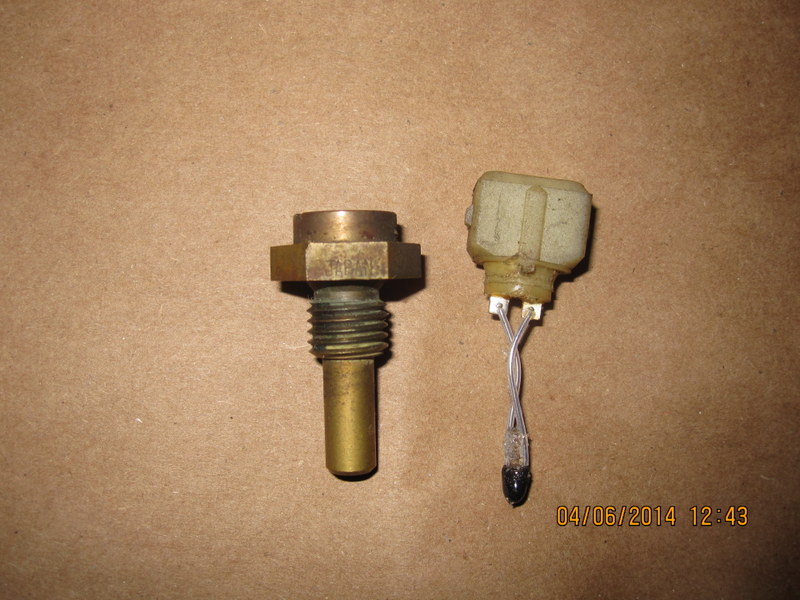
No editing allowed, so here's another post. A picture of the guts. You might also check the wires at the AFM sensor haven't rubbed through their insulation, causing a short. A piece of heat shrink, or tape or some glue might solve it.
-
I accidentally ripped apart a coolant temperature sensor trying to get the plug off. It came right out of the top with the EV1 connector attached, just minus the threaded metal portion. The actual sensor is just a blob of semiconductor on two pieces of wire, surrounded by a gel, probably silicone, inserted in to the brass housing. If you have an old coolant sensor it might be worth an experiment. I'm sure it would have a fast response time out of its housing.
-
I think that Fast Woman may be right and you have weak pump volume. But I wonder if the volume is low because you're pulling air in to the pump. There's enough gasoline getting in to keep a seal in the pump mechanism and let the pump work but it's pushing mostly air instead of fuel. Or the fuel is sitting at the bottom of the system, back-flowing in to the pump to let it hold pressure. Maybe. Check your fittings in to the pump and the filter and its fittings. Or a quick test would be to disconnect the inlet hose to the pump and run a hose without a filter to a gas can. Make sure the hoses seal tightly.
-
Check your cam lobes (a flat one will cause an intake backfire - check lubrication while you're in there), valve lash (a loose one is like a flat cam lobe), and fuel pressure (lean mixture cause backfires). Those things are always good to do in general.