Zed Head
Member
-
Joined
-
Last visited
Everything posted by Zed Head
-
 The other temp sensor is in the Air Flow Meter (AFM), called the air temperature sensor. The pins to check are described in one section of the FSM, page EF-22, and the values that they should read by temperature are in a chart on other pages, pages EF-53 and-54, along with the water temp sensor values. I don't know why they didn't just describe measuring the resistance at the ECU plug, it would make more sense, since it takes all of the connections and the sensor itself in to consideration. I have checked mine at only two different temperatures, a fall day and a winter day, and they read correctly so I have assumed that they were good. My car runs great, all sensors appear to work correctly, but I only get 16.5 mpg, mixed highway and short drives. I have the cold start valve fuel supply blocked, with a pressure gauge in its place, so I know it's not leaking (it was before). I haven't dug in to the tuning yet, plug reading etc., it's been too cold (which may be part of the low mpg). The AFM resistance can be checked at the ECU plug also, page EF-52. Described for the AFM removed, but the pin numbers at the ECU are the same as on the AFM itself. If anyone knows of a magic mileage improver, I would love to hear about. My two ton 95 Pathfinder gets better mileage. What brand of injectors did you get (question to jthill3)? I replaced mine with new BWD injectors. I have wondered if they flow the same volumes as the stock ones.
 -
In looking back at this post, I realized how hard it is to understand. Here is a simplified rewrite, from memory (so please confirm wire colors and check power before cutting or splicing anything). If you use the atlanticz.com alternator upgrade procedure on the 1976 280Z you will need to cut the yellow wire that goes to the brake warning lamp check relay under the passenger seat and resplice it in to a wire that is hot only when the engine is running. If you don’t the relay will be connected directly to the battery when you are done, therefore will not work correctly, and it will also slowly drain your battery. The brake warning lamp check relay is only supposed to have power when the engine is running. You can tell if you have this problem if you hear relays clicking when you reconnect your battery. The closest and easiest power source is to the fuel pump power line, which conveniently has a junction at the connector that runs next to the rocker panel also under the passenger seat. It is shown on page BE-7 Detail A in the FSM. I cut the wire to the relay, crimped on a flat male blade connector and inserted it in next to the GL wire in the connector. The fuel pump is only powered when the engine is running (unless you have wired it direct). I also put a 10 amp fuse inline so I wouldn’t fry any extra wiring if the relay shorted out (there were high water marks under the seat from previous ownership). Don’t forget to insulate the end of the yellow wire since it will still be connected to the battery. Or you can dig in to the wiring harness in the engine bay, find the splice and cover it up there. I think it is spliced in to one of the red and white wires. In the short term, if you just cut the wire to the relay but don’t repower it, the car will run (assuming it did before you started), and the battery will not discharge, but the brake warning light in the speedometer won’t show that your parking brake is on and it won’t show when you have a brake system pressure imbalance. I hooked mine back up to avoid that smokey burning smell, plus it will tell me when the next wheel cylinder leaks out. If you have a California car, you might find a similar problem with an EGR cut solenoid(?), from what I can figure out from the wiring diagram. If you use the zcarcreations.com procedure, the battery will not drain but the brake lamp in the speedometer will not go on when the ignition is turned on before starting the car like it is supposed to, to show that the lamp is working. I hope this makes more sense.
-
Well, it looks like you were exactly right. I resisted my normal urge to try many fixes at one time, and focused on that one area. Let water run down the chrome trim covered drip rail above the drivers door, and after about a minute I saw the water running down the top of the rocker panel and puddling on the floor. I had the carpet and padding pulled up and the door sill piece removed so I could see when it started and where it came from. In my case the water was actually running under the rubber piece as it had pulled up from aging and cracking. The water then ran down the door seal to the seam where the door seal ends butt together, across the seam to the inside, down to the top of the rocker, then down to the floor. I ran a bead of GE Silicone II under the rubber piece at the front of the door and also caulked up the door seal seam. Let it cure for a day, waited for rain but didn’t get any, so I went ahead and hosed the whole car down (fully prepared to find the next leak in line) and everything stayed dry. Thanks for the help. By the way, the car is actually very solid. I think that is just surface rust at the seam. But thanks for the advice.
-
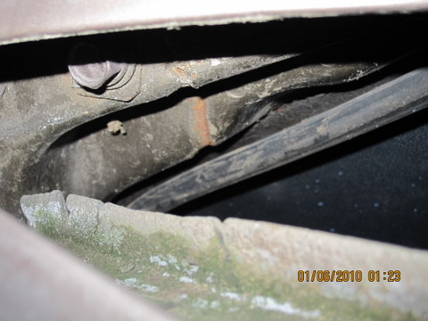
Thanks for looking. I had noticed that that rubber strip was pretty chewed up, it's at the bottom of the second picture, kind of green and with big cracks in it. I assume that's the one you mean. It actually has moss growing on it (pretty common up here). It looks like an engineering afterthought to keep sideways spray out, so I had overlooked it. But it does look like it's not fitting the way it was designed to. I'll build it up and try to make it look like the other side and see what happens next time I roll it out in the rain, or pour some water on it if it's dry out. It's going up on blocks tonight for a five speed swap so I won't know for a few days (barring unexpected problems). I'll get back with the results then. Thanks again.
-
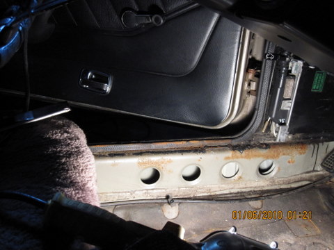
It's been raining here in Portland and since I have my car out of the garage and running well, I have found a large amount of water on the driver's side floor. I've looked through the various posts recently and in the past and was able to fix my leaky hatch using that information, but I have not seen a similar description of what I have recently found. I tore up the carpet and find that the water seems to be coming down the top of the rocker panel where the plastic trim meets the carpet and running over the edge in to the car. There is a large hole under the drivers seat, I assume from the PO parking nose up in the past and having the water run backward. I park nose down and the water is running off the rocker panel forward. I assume the water is coming down the front door jamb but I'm not sure how it gets there. Has anyone encountered this type of leak? I have also noticed what looks like a rusty separated seam behind the front of the door also. Could this be the entry point? Here are some pictures. Thanks for any help.

-
Windshield wiper switch on intermittent?
-
Thanks very much. The Courtesy Nissan link seems to tell the story. Red is 0.3. Red is the new brown at Courtesy Nissan. I wonder why they did that. But atlanticz still shows red at 0.69. So there is some dangerous information out there. If your red is not a Courtesy Nissan red you could have some burnt components. Or if you have a Courtesy Nissan 0.3 instead of red 0.69 you could have some mysterious fusible link burnouts. Thanks again.
-
Well, maybe that's how the red/brown confusion started. Nissan is giving out new red for old brown. Was there wire size information with the links? I have seen information on the web that shows the red links as being bigger than 0.3 mm^2. The atlanticz page for instance (although their diagram shows orange for the 76) - http://www.atlanticz.ca/zclub/techtips/fusiblelinks/index.html . The red seems designed for a much bigger load than the brown, based on wire size alone. If so, the red won't give the protection the brown was designed for. I will have to go down to Nissan and see what they have for links. Maybe they'll let me measure some wires. Thanks for the reply and the work on the schematic. It would make a cool poster for a garage or den.
-
Hello. I'm new here but I really could have used this two weeks ago. It looks fantastic, and I second the comment about eye strain. Mine are still sore from trying to figure out how the mechanical voltage regulator was wired. The color coding is great, and you've gone better than the FSM also by adding color to the fusible links. But I see that you show two red links under the two covers instead of two brown ones. The labeling on the side of my 76 fusible link holders definitely says B, G, and two Br, and the manual says that B, G and Br are used also (page BE-6). I've seen some discussion around the internet that maybe the brown is really red and you should just use red ones, but my reading leads me to believe that the brown links are real, at 0.3 mm ^2 in size, just not used on many models and not as readily available as the other ones. Can anyone comment on this? And thanks again for the diagram and I'm glad I have the car it comes from. Bob
-
-
Made a mistake in my first post. Original and corrections shown below. Sorry for the messy post. Basically what I've found is that both of the two popular alternator conversion instructions will allow the alternator to charge, internally regulated, but they both leave loose ends for other components in the 1976 280Z. I am new to this site but thought I would share something I found out about upgrading to a 1979 ZX alternator on a 1976 280Z. Using the atlanticz.com instructions - http://www.atlanticz.ca/zclub/techtips/alternatorswap/index.html - the brake warning lamp check relay will be "hot" all the time, even with the key off, since it is spliced off of the S line to the alternator plug. I found that the slight amount of current it draws would drain my battery after a few days. According to the FSM, California cars also have an EGR cut solenoid that would also be always energized. I assume that the old mechanical voltage regulator ran the S line and/or brake check relay through the ignition circuit (I did not dig in to confirm) so this was not a problem. You can tell if you have a similar problem after the conversion, if you hear relays clicking when you reconnect the battery, with the key off. Edit 11:41 am 11/12/09 - The following is wrong, it will not let the relay work correctly. The relay needs to be energized when the motor is running/cranking, but dead when the ignition circuit is on. {{{I fixed the problem by wiring the system like zcarcreations recommends - http://www.zcarcreations.com/howto/voltreg.htm - to get the relay back on to an ignition circuit}}} I ended up splicing the brake warning lamp check relay yellow wire, which energizes the relay solenoid, to the fuel pump circuit, which has a plug in the vicinity under the passenger seat. The fuel pump only runs when the motor is running. Edit 11:41 am 11/12/09 - This part still seems right {{{, but cut the S line splice off of the circuit and wired it direct to battery + terminal.} This also lets the alternator see mostly battery charge and not the voltage after the loads on the ignition circuit. I get a smooth 14.5 volts with the S line wired direct, but was getting a jumpy over 15 for the short time I had it wired through the the ignition circuit (measured with a good voltmeter at the battery).}}} That's all I have. I enjoy the discussions and hope this helps someone out if they decide to go with an internally regulated alternator. p.s. I also found that the dash voltmeter is pretty easy to adjust using the slotted adjuster on the back of the gauge.