
Zed Head
Community Member
-
Joined
-
Last visited
Everything posted by Zed Head
-
Are you saying it's a 240Z tower? AKA small body? I looked around for resto 240Z pictures and found a few. I couldn't find any 280Z pictures. The China body doesn't look like this 240Z, below. Three holes in the brace and it doesn't reach the top of the tower. It's an abomination! Not an expert. https://www.classiczcars.com/forums/topic/55998-picture-thread-early-vin-cars/#comment-501358 And first page of dspillman's resto thread. https://www.classiczcars.com/forums/topic/68900-finally-found-a-69-240z-51-time-to-finish-a-30-year-multiple-owner-restoration/#comments


-
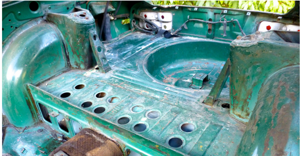
Are those not 280Z tall strut towers? Full size spare tire well. Vented hood. It seems to be some sort of hybrid Z.
-
But, it looks like their replication process has some flaws. Or the narrator misheard 1978 280Z as 240Z. Wonder what the rear strut towers look like. Found it.


-
This company has come up before. Stumbled a cross a video about it. $9,500 for a "new" 240Z body. About 0:50 in. https://youtu.be/cBBZrjwqWZc?si=hYSPDBMdPgUH3oPH

-
Another high mass item is the crankshaft damper. The belt-off test will tell something.
-
Just watched the video. Not sure that Yarb did (no offense intended), that noise is terrible. Seems like whatever it is must have some mass, to keep spinning after the engine is shut off (from your title). Can't tell if the engine is spinning though in the video, although it seems to be shaking. Also don't know if you have your foot depressing the clutch pedal or not. It might be the input shaft to the transmission spinning transmission parts. Try the test with no belts and your foot depressing the clutch pedal, with the transmission in gear. That will stop any of the transmission parts from spinning.
-
Courtesy Nissan down in Texas used to have one. Everybody used to use them to buy Z parts. But they revamped the web site and that part of it disappeared. The guys that put it together originally said they were going to bring the catalog back but it never happened. I'd guess that "corporate" didn't support them. It's just another bland dealership web site now. https://www.courtesynissan.com/parts/
-
Pot, kettle, both black.
-
Still curious about origin. As I understand things the aluminum drums are discontinued from Nissan. So, it would have to be either NOS or an aftermarket reproduction. I don't see any casting ID marks like those on the originals so I assume they're aftermarket. Not saying that they're bad, just curious. I wonder where things come from. Who made them? Probably no way to find out. https://datsunparts.com/products/datsun-z-car-70-71-72-73-74-75-76-77-78-240z-260z-280z-510-rear-aluminum-finned-brake-drum-sold-as-pair-only-prepay-intro-offer-march-2025?_pos=4&_sid=0010228b6&_ss=r NOTE: The company that makes these is the same company that makes rotor hats for the McLaren 12 "Dean, I got the new drums on Saturday and put them on the race car yesterday. They look to be a really nice product. Thanks." David W. Plott 1973 240Z ITS Class SCCA Mount Juliet, TN This was on the drum search page but not the final page of the specific drum. Looks like an "off-shore" copy. I don't know how a new drum could be "engineered" in the US. Anyway, just keeping track of things going on. You'll be fine! Good luck. https://datsunparts.com/search?q=drums&search= Datsun Z Car 70-78 240Z-260Z-280Z, 510 Rear Aluminum Finned Brake Drum 6.5 lbs each drum as opposed to 12 lb each for cast iron versions. 43206-E4100 original Nissan number PRICE IS FOR A PAIR AFTERMARKET US ENGINEERED Correct and proper...
-
Where will you be tested and do you know the extent of the test? I used to test in Oregon and they only did two things - checked for a catalytic converter and measured idle emissions. Some areas do complete visual inspections, and test idle and 2500 RPM under-load emissions.
-
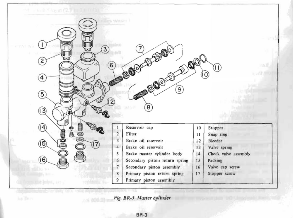
There are many parts in there. Considering the time you're spending on it, it might be worthwhile to try a parts store MC just to be sure it's not that. Although, they are spendy. https://www.oreillyauto.com/shop/b/brakes/brake-hydraulics/brake-master-cylinder/3bff094046ed/v/a/16441/automotive-car-1973-nissan-240z?m
-
Have you measured the inner diameter? Curious if they are turned used drums or NOS.
-
It's back. https://www.carpartsmanual.com/datsun/Z-1969-1978
-
The carpartsmanual site is back up. Might not find it not here, if it is not original to the car. 🥴 https://www.carpartsmanual.com/datsun/Z-1969-1978
-
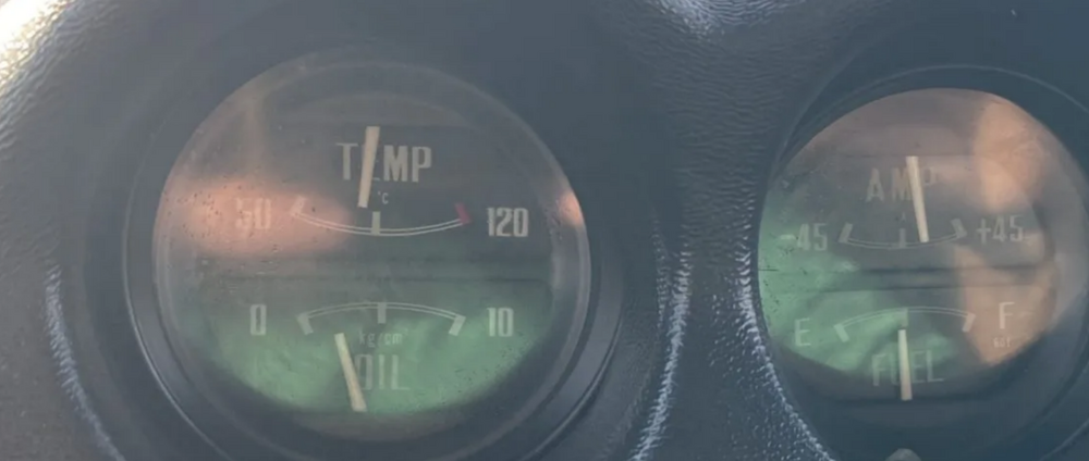
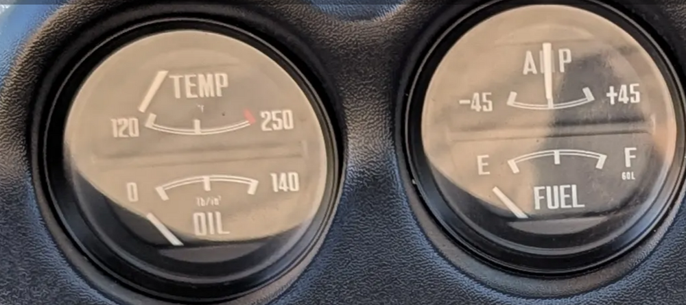
Maybe you meant early 71? When I was browsing around I found both in 1971 cars. Just did another browse and am finding more 140's than 90's. Looks like maybe early VIN cars had 140. Not a big deal, just a curiosity. Funny though, mid-scale is either 45 or 70 psi. Maybe they changed the gauge because oil pressure looked low on the 140 gauges. Picture 30 https://bringatrailer.com/listing/1971-datsun-240z-346/ Picture 94 https://bringatrailer.com/listing/1971-datsun-240z-329/
-
I think that this has happened before and the guy that runs it is a member. I have a vague memory of him replying. Anybody know? https://www.carpartsmanual.com/datsun/Z-1969-1978

-
Looks like the later gauges also went to a 90 psi limit from 140. So, limited availability, besides the font. BaT is a great place to browse around and see the differences. Good luck. https://bringatrailer.com/listing/1970-datsun-240z-137/ I even found one with metric scales. https://bringatrailer.com/listing/1971-datsun-240z-324/
-
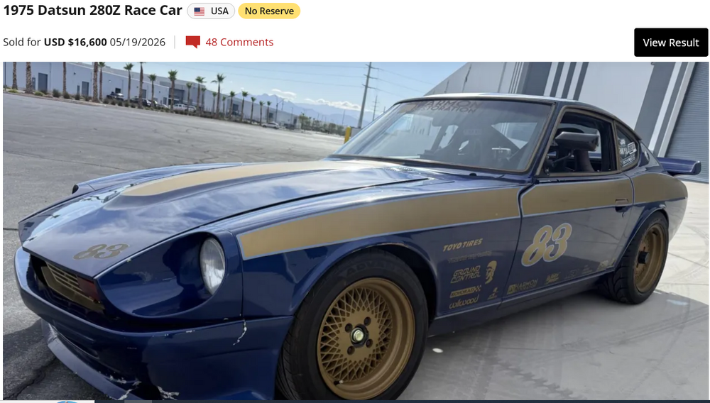
$16,600 for the Hooner Whale Tail Z. The Z market is unpredictable. Beat-up/beat-on street legal race car with unknown miles on "built" engine, no air filter, retarded timing to run street gas, and suspect rear suspension damage. Good money! Driving videos make a difference, apparently! https://bringatrailer.com/listing/1975-datsun-280z-71/
-
Nissan changed the font details on the gauges over the years so if you're doing a precise restoration, be careful. I don't know when the changes occured but I know that 1976 and 1978 were different. You could probably change the face plates if necessary. But it sounds like your gauges might actually work, something else is broken. Might help to define Good luck.
-
This bot gets very close. But even after coming back to edit the post it's still not quite right. devidevi, guess what you got wrong... Edit - actually probably a person using/training a bot. Using the site for AI/bot development. Mike should get paid! @Mike
-
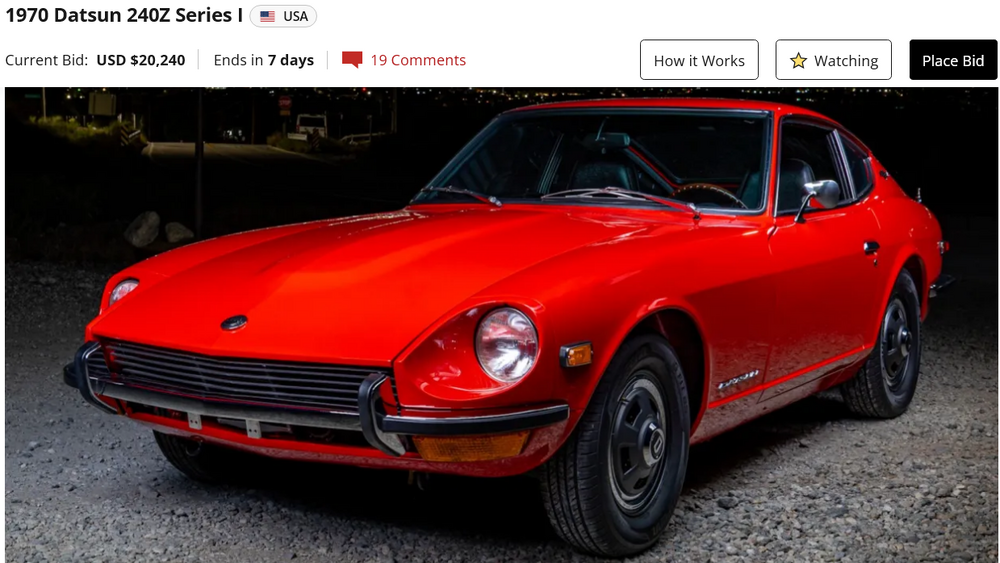
Old red 240Z. https://bringatrailer.com/listing/1970-datsun-240z-144/
-
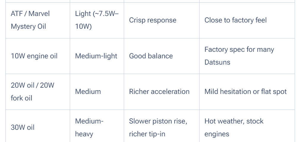
Sorry for the rant. I worry about being surrounded by people on their phones asking them what to think. Here's an example of how detailed experience gets distilled down to something by "AI". You can see the pieces that remain, like unchewed kernels of corn or chewed gum, in the AI response. This guy Keith Williams seems well known in Datsun world. Why not just read his original material? It seems more informative than what the "super-brain" produced. Anyway, it looks like experimentation is required. Good luck. https://www.311s.org/su-setup/su-setup.html Dashpot Oil On acceleration the mixture needs to be richer or you will get stumbling. The oil in the dash pot slows the rise of the piston. The piston being lower than it wants to be causes the mixture to be rich. Generally speaking you want to use the thinnest oil that stops stumbling on acceleration. Roadsters tend to be quite tolerant of running rich so thicker is better than thinner. However, too thick will over richen and cause the acceleration to feel flat. The correct thickness will have a crisp acceleration. The factory spec is 10w. That is in the range of ATF and MMO. 3 in 1 is thinner. In one Z I did I ended up with 50w before it would accelerate cleanly. The synthetic oils do tend to be thinner than regular oils so I'm not sure what the "real" viscosity of the synthetic is. Motorcycle fork oil works well, comes in convenient bottles, and in lots of weights. Single weight engine oil comes in 20, 30, 40, and 50 weight but I haven't seen 10w. If you're being fiddly you can mix weights to come up with in between weights. I use fork oil for the thinner weights and single weight engine for the thicker.
-
Are you guys really looking at and absorbing the AI "stuff". If 7.5W - 10W is light how can 10W be medium-light? What does "good balance" even mean? (Nothing). Richer tip-in? Has no meaning. Richer acceleration? Feels like it has meaning but when you really think about it it doesn't. Are the recommendations to fix a "best use" or to avoid it? "Close to factory feel" and "hot weather" and "flat spot" are all under Best Use. The AI's are designed to make the users feel good. Like a drug. Apparently an addictive drug, Don't overdo them! Check out the Sources. They're the usual suspects. The AI just blends them all together and excretes something that looks authoritative.

-
Here's a tool for setting booster rod length. I just picked one site, they're all over the internet. Search "booster master cylinder tool". D and C Extreme IndustriesMaster Cylinder to Booster Measuring Tool | D and C Extre...SKU# Wil 260-18027 Shipping $8.00
-
A couple more things to consider, tools for problem solving: Air in the hydraulics can be "pumped up" to get the brakes to work. Each pump compresses the bubble(s). If you're just getting a pedal that drops and pumping doesn't help, that's a seal problem, not an air problem. Unless it's a really big bubble. I had a big bubble from switched calipers. It's burned in to my brain. I could lock up the backs with pumping but the fronts were useless. And, a leak at the back of the master cylinder will not be visible until it drips down the firewall or comes out of the bottom of the booster. Don't drip brake fluid on your paint. It leaves a mark.