Zed Head
Community Member
-
Joined
-
Last visited
Everything posted by Zed Head
-
Here's bolt-in adjustable - https://technotoytuning.com/nissan/280z Her's straight lowering, no adjustment - Motorsport! Eibach Progressive Spring Kit, 9/74-78 Coupe, 74-78 2+2 (260Z-280Z) - The Z Store! Nissan-Datsun 240Z-260Z-280Z-280ZX-300ZX(Z31/Z32)-350Z-370Z Parts
-
My words of wisdom would be - "do more investigating before pulling the head". Unless you've been itching to do it and this is just a good reason. I can't remember if your engine is stock or modified but there are a few other fitting and rubber hoses up by the thermostat, on top of the intake manifold, that can leak. The heater block for the AAR and its hoses. There are also three potential leak spots at the housing, in addition to each sensor/sender/switch. The hose fitting, the gasket between the hose attachment and the hosuing and the housing to head interface. Just saying, many of us have done the disassembly of one part or another only to find that it wasn't the source of the problem. From what I've seen and read, the typical leak spot for coolant through the gasket is at the back on the passenger side, not the front driver.
-
I think that the original setup uses plain washers. You can see them called out in the attached link. The nuts are hard to reach, a stack of two or three extensions, short and long to get the right overall length, a mirror, and a good eye will let you reach all of them. It's easier if you take the heat shield off. But for your header, you better make sure that the header flange is the same thickness as the intake manifold flange or modify the "thick washers" (yokes by Nissan terminology) to get good clamping. And you're probably better off to use one of the thick intake/exhaust gaskets, instead of a thin one (Fel-Pro for example). The MSA gasket is good, and Victor Reinz brand. Also check the flange for flatness. You can still get the studs and nuts from Nissan also. They're not expensive. I don't know where MSA gets theirs. Datsun 280Z Manifold, Egr. Index
-
The only time the engine sees at the initial timing point is when the throttle is closed, assuming ported vacuum is used for the vacuum advance, and the centrifugal is stock and working properly. Otherwise, throttle open applies vacuum advance and increased RPM applies even more. Those two will determine how the engine runs when driving. In short, make sure your advance mechanisms are working properly and they're what you want for mileage and power.
-
Feel free to disagree with anything below. It's just my understanding as of right now. Started writing and kind of went crazy. The XR-3000 and the GM HEI are very similar in operation, and are basic module replacements, no work on the distributor,but ending up with better electronics. The Mallory and the ZX and the 123 are distributor replacements, the ZX and the 123 probably give stronger spark. The Pertronix is basically a swap of similar electronic systems, no performance benefit. Your signs do look like ignition module failure. The transistor in the module is supposed to control current to the coil. The fact that you get sparks when just turning the key suggests that the transistor is shorted. The factory service manual might have a method for checking the module if you have the tools. Even so, the electronics technology is old and out-dated. On the options: 1) crane xr-3000 with ps-91 coil - the technology for "dwell" control is common today. The $20 GM HEI module has the same technology. that's where the "high-energy" comes from, maximum coil charging all the time in a unit that can handle the current flow. The XR-3000 recommends bypassing the ballast, the XR-700 does not. An example of old versus new. 2) msd 6al (expensive) - The MSD is a capacitive discharge system. It only uses the coil as a transformer. And the M, for multiple, is only active at low RPM. At mid to high RPM there's only a single spark. 3) 280zx distributor E12-80 module (30 y.o technology) - The ZX has the "dwell" control technology also. You can buy new modules, but they are expensive. If you buy a distributor you'll have to make sure the advance curves are what you want. 4) pertronix ignition unit ( would I need a 240z dizzy) - Pertronix was one of the first electronic units available and have done a good job of holding market share. I think that the under-cap module can't handle the current flow to provide big spark though. They recommend resistance on the primary circuit so can't flow as much current as the others. 5) Mallory - another early system that has lasted. They recommend factory plug gaps, and use an undercap module also. 6) 123ignition - this unit has dwell control and the USA distributor has just had adapters fabricated for use on the L6. It's not "two wires and go" though. You need a PC to program it if you get the programmable, or you need to pick an advance curve for your engine. It's the most flexible though, but is a complete distributor not just an ignition module. I've seen internet threads from 2004 so they've been around for a while on the European cars (Alfa Romeo, Porsche, Jaguar, etc). Here's some links - 123ignition - Nissan L6 Forum - HybridZ Datsun Conversion | 123IgnitionUSA.com What is 123Ignition about? - Perfect Timing - w/ "Formula" Technology | Ed Motorsport! Mallory Unilite Distributor, 70-74 240Z-260Z, *75-83 - The Z Store! Nissan-Datsun 240Z-260Z-280Z-280ZX-300ZX(Z31/Z32)-350Z-370Z Parts Motorsport! Crane XR-3000 Electronic Ignition System, 70-73 240Z - The Z Store! Nissan-Datsun 240Z-260Z-280Z-280ZX-300ZX(Z31/Z32)-350Z-370Z Parts https://prestoliteperformance.com/media/instructions/mallory/Mallory_Instructions_unilite_distributor_wiring_diagram_test_procedure_1214M_0000.pdf http://www.cranecams.com/uploads/instructions/9000-0700_.pdf
-
No offense intended. A new thread with a link to this one might work also.
-
Are trying to sell a car, indirectly? The post you replied to is over two years old. If so, say so.
-
Consider the GM HEI module swap if you want to go inexpensive. It might be the best value for the money out there, but does take a little bit of wiring work. Combine it with an HEI coil and you'll have a true high energy system, designed for .040" or greater spark plug gap. At least one of your options above (Pertronix, no offense to users) is electronic but not high energy. If you have a dual pickup distributor you're going to lose one of them in any case except a stock replacement. Not really a big deal, the second pickup is an emissions and convenience item.
-
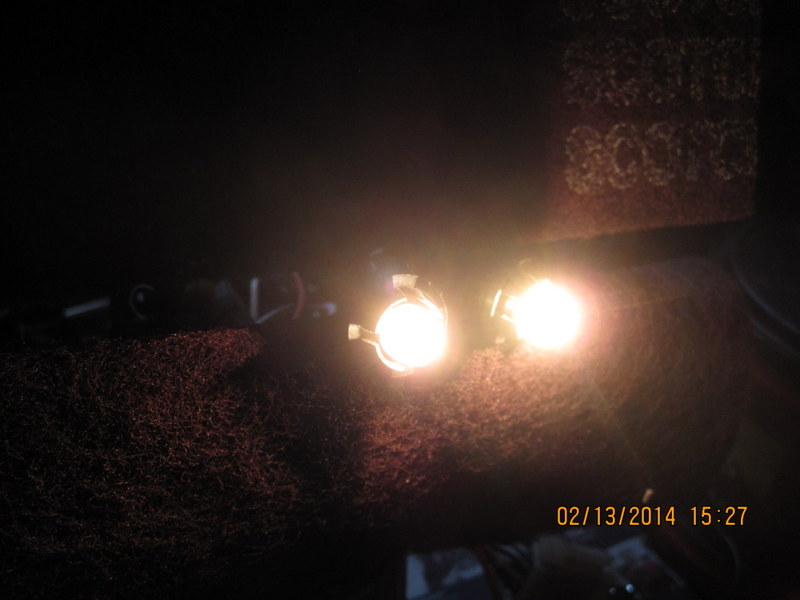
Here are some pictures of the Eiko bulbs, and a comparison. My only "small-form" bulb is labeled LIFE 12V3.4W. The Eiko bulb is labeled 12V4W3E. My camera can't capture the look of the filament, only the size of the glow. The Eiko filament gives a nice wide glow, compared to the LIFE bulb. I don't know if LIFE is a Nissan vendor or aftermarket from the past, I pulled it from an old gauge. So it's old v. new which could also be a factor in brightness. The Eiko bulb slipped right in to the fitting, no issues. One possible down-side to the Eiko bulb is that it does not have a supported filament. Apparently that can affect longevity in a vibratory environment. Who knows... I won't be installing these for a while. The dim 1 watters will do until I have some reason to remove the gauges. The Eiko bulb is on the right in the attached picture.

-
How about putting the clip on the shaft without the handle? It should sit deep in the groove, firmly placed, not easily removed but loose enough to wiggle around. That's how it will be when it's in the handle.
-
14 hours left! Looks like i***0 has an automatic bid set up. I asked a question but Gas Monkey never replied. Bidder Click here to know more about anonymous user IDs Bid Amount Bid Time i***0 ( 13Feedback score is 10 to 49) US $7,160.00 Feb-06-14 16:40:12 PST d***2 ( 5 ) US $7,060.00 Feb-10-14 20:56:23 PST z***a ( 3 ) US $6,860.00 Feb-09-14 07:25:54 PST
-
The pre-ZX Z cars had two fuses for the headlights. left and right. If one burned the other light could still get power through "back-feeding" from the other light. You might check your headlight fuses. If you don't have it already, download the Service Manual for your car. Index of /FSM/280z
-
That video is perfect. 9.5 second build-up, action, end.
-
siteunseen may have inadvertently steered the discussion off-track with Post #2. The question is how get the handle on, not off. Handle in hand, clip in place in its two slots ready to expand as it passes over the nose of the splined crank shaft, press the handle on to the shaft and the clip expands and slides down the shaft, closing up again when it gets to its slot on the shaft, locking the handle in place. The only reason to not be able to do this is either that the clip is not expanding far enough to slide down the shaft, or it's catching in something on its way down, or that the shaft is bottoming out in the handle hole before the clip gets to its slot. zKars is right, this is sounding way more complicated than it is. Put clip on handle, put handle on shaft, press and pop. That's all there is to it.
-
Might just need a little lubrication. Smear a little bit of oil or grease on the tapered portion of the splined shaft that the clip has to slide over.
-
They do use salt in the Portland Metro area, along with gravel and sand. Magnesium chloride (a "salt" in chemistry terms, not the common usage). They add a corrosion inhibitor to it because it's worse than sodium chloride for causing corrosion. You can see the stripes on the road when they lay it down the night before they expect some ice. The rain that usually follows though will wash away the salt. But the worst thing about driving around the Portland area after an ice or snow event is the small rocks thrown up from the gravel. It takes a few days for the sweepers to clear the roads and you'll hear them pinging and popping off the car and windshield until they do.
-
Here's another clue - the stock springs have quite a bit of preload. You would have had to crank the compressor down quite a bit before they could be set free. The Tokico springs barely have any, just enough to fill the space. You can press the top hat on by hand, it you have the weight, if I recall right. I have them on the back of my car, the front is waiting.
-
I've had a couple of stock spring sets off and they were black with a colored stripe, about one inch wide. I assume the color had some meaning. Red might be Tokico. It's a bright red. I would test a section of paint with some acetone, MEK, or similar and see if the black is soluble. Don't know for sure but the manufacturers probably use a two-part epoxy or urethane, or a powerdercoat, that wouldn't be soluble. If you're lucky the white ID numbers are two-part also. 5022-F and -R are the 280Z Tokico lowering spring numbers. The stock 77 springs jack the back of the car up pretty high. If your springs were stock you would probably notice.
-
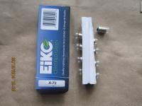
jfa supplied a link in Post #2. The specs are on Planet Bulb's site. I assumed hours, based on other bulb specs, but it might be minutes! That would be a little over a day though, so unlikely. The model is A 72.
-
Definitely not Z weather in the Portland OR area. This is coming on top of the foot of slightly melted and refrozen snow - ...FREEZING RAIN ADVISORY IN EFFECT FROM 4 AM TO NOON PST MONDAY FOR THE PORTLAND AND VANCOUVER METRO AREA..
-
If you didn't put a new bend in the spring end for the perch seat then you ended up at the same height with the same number of active coils. You just cut the seat of the spring off. The picture of the cut piece kind of shows that. Easy to miss since "coil" is a fairly generic word.
-
Could you connect power and give it a test? Or test unpowered to see if is grounded, either directly or through a device (60 ohms is a typical device resistance). If you find power you could remove fuses until it goes away.
-
Look here at the bottom of the Motorcycle Tank section. There may be other rust removers that can be sprayed also, this is just one description I found. Evapo-Rust rust remover description page Here's the click-through: Evapo-Rust rust remover chassis testimonial I think that you could make a solution of Naval Jelly and paint it on also. http://www.loctiteproducts.com/p/s_trmt_naval/overview/Loctite-Naval-Jelly-Rust-Dissolver.htm
-
Check out the bid history. Starting price was $500. I think that's what they would have taken for it. People are paying for the name. Edit - actually the car doesn't look too bad. Might be worth $6-7000 to the right person. Anyone know what the little mini-console is next to the driver's right knee? i***0 ( 13Feedback score is 10 to 49) US $6,760.00 Feb-06-14 16:40:12 PST d***c ( 272Feedback score is 100 to 499) US $6,660.00 Feb-07-14 05:01:02 PST i***0 ( 13Feedback score is 10 to 49) US $5,000.00 Feb-06-14 16:10:07 PST p***d ( 42Feedback score is 10 to 49) US $3,502.00 Feb-06-14 14:06:28 PST f***g ( 950Feedback score is 500 to 999) US $2,777.41 Feb-06-14 15:56:31 PST d***c ( 272Feedback score is 100 to 499) US $2,666.00 Feb-06-14 12:41:13 PST e***u ( 50Feedback score is 50 to 99) US $2,300.00 Feb-06-14 12:51:56 PST o***o ( 46Feedback score is 10 to 49) US $2,225.25 Feb-06-14 12:38:36 PST d***c ( 272Feedback score is 100 to 499) US $1,666.00 Feb-06-14 12:41:00 PST l***i ( 100Feedback score is 100 to 499) US $1,550.50 Feb-06-14 10:52:17 PST 1***a ( 272Feedback score is 100 to 499) US $1,500.00 Feb-06-14 12:37:36 PST y***r ( 401Feedback score is 100 to 499) US $899.00 Feb-06-14 12:32:48 PST e***u ( 160Feedback score is 100 to 499) US $797.77 Feb-06-14 12:30:27 PST e***h ( 308Feedback score is 100 to 499) US $777.77 Feb-06-14 10:42:42 PST p***u ( 591Feedback score is 500 to 999) US $750.00 Feb-06-14 08:36:33 PST 4***e ( 1141Feedback score is 1000 to 4,999) US $560.00 Feb-06-14 08:56:43 PST Starting Price US $500.00 Feb-06-14 08:30:00 PST
-
Maybe you have bad connection on the S wire. The internal regulator uses the S wire to set output, raising output until S is at the set point. You can test it by running a jumper from the S terminal directly to the battery positive or the starter solenoid lug. If voltage drops to normal, then your S wire has a bad connection. I've had a bad connection right at the T connector on the alternator. You might just clean that up and make sure it's tight also.