


Zed Head
Free Member
-
Joined
-
Last visited
Everything posted by Zed Head
-
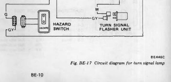
 The diagram suggests that the short that blows your flasher fuse would be in the Hazard switch, or the flasher unit itself, or the wires between the fuse and the flasher unit. The flasher unit provides resistance to stop a short to ground after it from blowing the fuse, I think. Edit - but it would have to be a constant short circuit that doesn't pull enough to blow the fuse by itself. Using the signal switch pushes it over the edge. Since the signal switch completes the circuit to ground. The voltage is always in the wires.
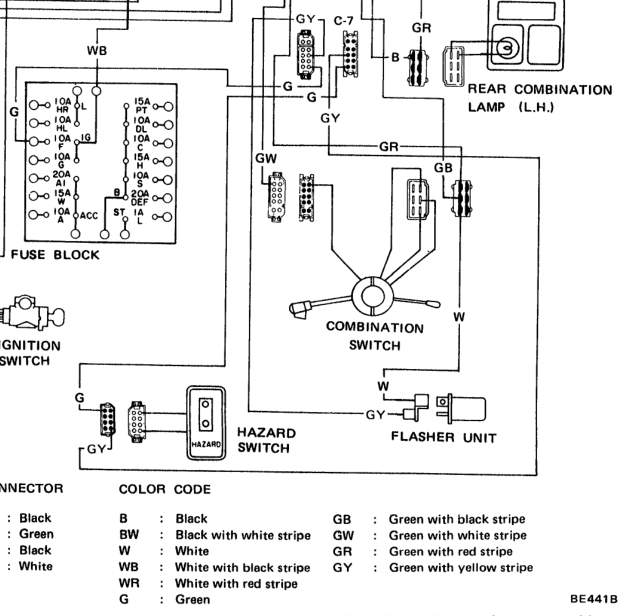
-
What about the flasher fuse? That's the one that is blowing, right?
-
The dot is only for aiming. The measured area might be much broader. The farther the device is from the area, the broader the area is that is measured. Probably best to hold the pyrometer straight and scan over the fuses if you want to find a hot one. And the closer the better for a small area. There is a bunch out there about all of the various details, some it way in to the weeds. Here's one reference. They're not really designed for small area measurements. I have one that has a socket for a thermocouple. That's what you'd really want for measuring fuses and other small areas. https://www.williamsonir.com/blog/3-tips-proper-pyrometer-maintenance/ " For single-wavelength sensors, alignment is critical as the pyrometer takes an average temperature of whatever it sees in its field of view. Therefore a single-wavelength pyrometer needs a full field of view of the target to make an accurate measurement, so as not to average in other non-target temperatures. "
-
The technical parts of the thread were interesting. Thanks to all that contributed. It's still an interesting topic. I'd like to see the instructions for building the steering wheel, from the factory. That would be cool. You can see that they covered up a pretty ugly piece of steel. The welds aren't even very good.
-
To the guy on the BATS discussion. Never mind.
-
Not me. You're projecting that other guys comments on to me. I don't need help.
-
Consider adding a load test to your repertoire. A test light that pulls a few amps. Connections can open when they heat up from the current.
-
Actually, you didn't really say much in that post. A few names to research if a person wanted to, quotes of someone else's posts. Kind of thin. No details, just references to broad processes. Anyway, manufacturing of parts like this is an interesting topic, when you get in to the fine details. Where the technology becomes more like art. Overall, in this case, it seems that the process of forming the wood was almost too good. So good that the final product seems like plastic.
-
My description was based around "how do they get the steel in to the wood and keep it there?", how do they keep the wood from regaining its original form, and the hot technologies of the time. It certainly could be wood. Steam bending/forming is an ancient ship building technique. Resin infusion of wood is a thing also. So it might have started as a solid piece of wood but had resin infused to lock it in to shape once it was formed. If I was doing the forensics I would look very closely at where the steel contacts the wood. The inside not the outside. The fine details around the weld beads and where the spokes enter might tell a story. You could also burn a piece and see what it smells like and how it smokes. Polymers/plastics have a distinctive odor when they burn and tend to produce a black smoke. Many ways to get there, probably many technologies involved, probably combined to get the desired end result. https://en.wikipedia.org/wiki/Steam_bending https://en.wikipedia.org/wiki/Impregnation_resin#:~:text=The impregnation of resins into,into a solid substance state.
-
I just skimmed over the thread. But it seems likely that this would be a wood-fiber reinforced polymer composite, with the original bulk material in the form of what would be called "bulk-molding" compound. A blend of wood fibers and reactive resin ( the precursor to a polymer) that would have the consistency of Play-doh. In that era the typical resin might be a polyester, like they used for surfboards. The mold might be pre-coated with a clear resin, similar to how hot tubs are made, maybe a polyurethane clear coat, for durability and weather resistance. Then the molding compound and steel frame would be placed in to the mold on top of the previously sprayed coating and the mold halves pressed together to form the wheel, then the whole assembly placed in to an oven or autoclave for curing. The end result is a wood-fiber reinforced polymer composite with a hard durable clear coating. The coating is then polished to give the final surface. So, definitely not just "plastic" unless you consider the wings of a stealth fighter to be plastic. But, not really wood either. A high-tech, for the time, product designed to look like wood but be better than wood. Wood has problems. Just one possibility. You can't spend a lot of time arguing with people who rail against "plastic:". The word is just too undefined, it doesn't really mean much. Literally, it means "formable".
-
I don't think that you're talking about the same measurement.
-
Maybe the clicking/knocking noise is the fuel pump. Not turning. The engine does not seem to be spraying any fuel. You did not mention fuel pressure. Very important.
-
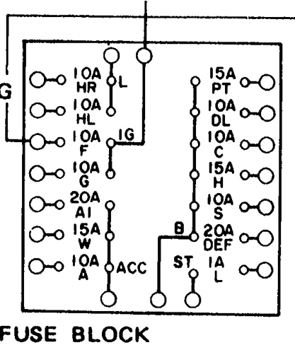
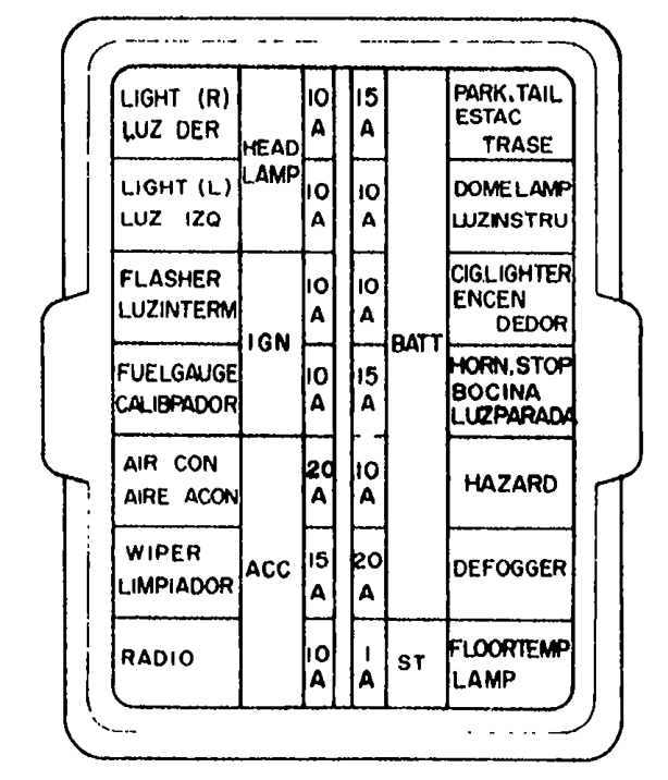
Check the back of the fuse box. Fuses blow from heat. Maybe you have some corrosion, causing heat, or a short circuit to the AC circuit.
-
AC has its own fuse.
-
Any mechanical component from the brake pedal to the MC piston could be too tight. Each contact point is meant to have a small amount of play. The play at the pedal to MC can be hard to get right because of cramped quarters. I used to adjust mine so that I could feel when the MC rod was just contacting the MC piston and the clevis pin was loose in the holes. You can adjust the rod with a pair of pliers while everything is connected. It will spin when the locknut is loosened. People have had problems using the FSM numbers on their booster rod because of the variety of aftermarket parts and gaskets and adapter things. There's a tool you can get that will measure the depth then transfer it to the rod if you're not confident of your measurement technique. Somebody has posted it in the past, here's an example. https://www.amazon.com/Sunyat-Power-Booster-Pushrod-Adjustment/
-
Might be that you have a hydraulic pressure buildup or hang up, not releasing quickly, but releasing slowly. So you're not catching it by the time you get a wheel lifted. You could lift the front end and confirm that the wheels spin freely then drop it down and go for a drive using only the parking brake. Check for heat. That would tell you if the pads are dragging all of the time or only when you pressurize the hydraulics. Or you could just let them cool down and go for a drive using only the parking brake. If it's a slow leakdown you'll get the same result.
-
Just found an old thread where I was so focused on the turn signal that I didn't notice the involvement of the hazard switch. In case anybody finds it. Weird how the brain evolves...
-
I would plug it in and back probe. Or identify the trace and/or switches that go from G to GY and measure continuity. I can't remember what the inside of the switch looks like.
-
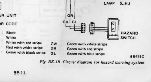
p.s. the Hazard switch just lets power pass through from G to GY when the switch is not activated. Looking at Post #16 it seems like you have a Hazard switch problem. The power is not getting through.
-
I haven't followed the whole thread but the wiring diagram shows a different power supply and a different output through the Hazard switch, for turn signal versus four way flashers. You're either not getting power or you're not getting output from the Hazard switch. I would confirm power in on G, then power out on GY, right at the Hazard switch, firstly.
-
Any chance it's the bulb(s) or their sockets? When you say "don't work" do you mean no light at all, or no flashing? I'd put a meter on the pins in the bulb socket. Sometimes they look okay but don't actually contact the bulb terminals. Plus you can test power supply and ground. A look at the wiring diagram will show which pins do which.
-
https://francieandfinch.indielite.org/book/9781931128407
-
Maybe it's not the brakes. Could be wheel bearings.
-
How about pressurizing the cooling system and waiting to see which cylinder fills with coolant. Watched a youtube video where the guy forgot and left his pressurized overnight. The leak area was apparent.
-
Curious, are your E12 modules Nissan brand or aftermarket? I think that that is one of the issues a person has to consider. The E12 aftermarket does not have much competition so the product quality is sketchy. Look at the price difference on the only two available on Rockauto and then look at the pictures. Who knows what's going on... https://www.rockauto.com/en/catalog/nissan,1981,280zx,2.8l+l6,1209338,ignition,ignition+control+module+(icm),7172 Anyway, you can get get lost down a rabbit hole when you start modifying things, as you've already found out. Here is a write-up about the HEI module from EuroDat. In short, there are five connections that you need to worry about. Get those five correct and you can put the module wherever you want to. I have seen people put it in place of the E12 module on the side of the distributor. The five points are the two trigger wires, red and green to G and W on the module, the B for battery, the C for coil negative, and the ground contact through the mounting hole. There is another writeup in the downloads area showing how to jumper the board in the E12 module but it seems overly complex to me. Just extend the green and red wire from inside the distributor. You have to put your electronics nerd hat on to get in to it.

