Namerow
Community Member
-
Joined
-
Last visited
Everything posted by Namerow
-
Very nice photo documentation and write-up. Looking forward to your next installment.
-
@zKars You got?
-
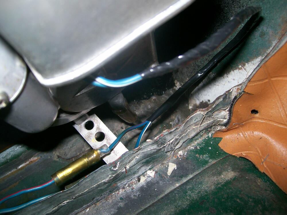
The metal strap just keeps the base of the antenna body from moving fore-aft or side-to-side. It doesn't support any of the weight. Instead, the weight of the antenna body is supported entirely by the fender mount (where the mast pokes through fender). In the picture below, the strap is obvious, but the body-mounted stud is hidden. If you look closely, you'll also see the drain tube and the point where it exits through the grommet at the bottom of the body cavity (this is also the place where the little centre pins for the interior panel plastic rivets go to die).
-
I remember reading an industry website several years ago where the writer predicted that the only distinction between mainstream brands of power tools would be aesthetics (colours, textures, legacy, etc). Looking at what I see in 2025's North American market, I'm inclined to agree. But I think that only applies to ~ revered old-school USA brands like Porter, DeWalt, B&D, etc. For comparison, look at what's happened to old-school non-automotive brands like 'Schwinn', 'Singer', 'Sunbeam', 'GE', 'RCA', etc. Offshore' brands (Bosch and Makita come to mind) might have a little more to offer than just marketing. Unfortunately, there's no universally-accepted evaluation standard. These days, it's just the 'Wild Wild West' of YouTube evaluators Caveat emptor.
-
Great post. This info really needs to be added to 'Knowledge Base'.
-
It's there strictly for water management (by design, it can't contribute to sealing off exhaust gases from the cabin because covers only the top and sides of the hatch opening, while remaining completely open to the outside at the bottom). If your Z is a later-model 240 (where there are no vents on the lower hatch surface), the most likely culprit will be your main weatherstripping ("the large weatherstrip that's been installed years ago"). It may have lost some of its original shape after years of living 99% of its life in a crushed state while the hatch is closed. IIRC, some owners also found that the gasket around their taillights housings had deteriorated, allowing exhaust gases to enter the cabin through the rear panel. If your Z is an earlier-model 240 (vents on the lower hatch surface), that's a whole different (and more challenging) ballgame. There are several threads on the CZCC site that discuss problems (several) and remedies for this design.
-
I remember the vendor, 'Auto World', from back in the 1960's (I still have their 1965 catalog sitting on my book shelf). I didn't realize that they were still in business. The website pays some homage to the original operation, but doesn't make it clear whether there's a historical link between 'then' and 'now'... "Oscar Koveleski founded Auto World in the basement of his home in Scranton, Pennsylvania in 1958. The small mail order hobby business grew to great proportions and became known for its annual product catalogs, which were filled with every car-related item an adolescent hobbyist might desire." The current iteration of Auto World is based in South Bend, Indiana.
-
I just used the link that Zkars provided in his #2 post. The Gyraline website currently features their Black Friday deal and offers the option of having the price displayed in the currency of the customer's location. IIRC, I had to select the 'G1' (iPhone) or 'G2' (android) product first, add it to my Cart, and then go to the Cart to see the price. I tried this posing first as a Canadian customer, and then as a American customer. The quoted price in Cdn $ for a Canadian customer was significantly higher (numerically) than that for an American customer -- but maybe that was purely the result of performing a currency conversion. Additional costs for shipping/handling and duties/tariffs might get tacked onto the Canadian price afterwards and not become visible until later in the check-out process. A quick internet search indicates that Gyraline was incorporated in Delaware in March 2024, with operations based in California and Texas. I have no idea where they do their manufacturing. Given the the nature of the design and the relatively low production volumes, it could be as simple as contracting out to a US-based additive manufacturing company ('additive manufacturing' = commercial-grade 3D printing).
-
Good question (and my mistake). The research project that I reviewed involved the development of an app for a smart watch.
-
For the 'G2' android version, the Black Friday sale price (15% discount) is US$340 (plus shipping, tax, etc). Lots of videos on You Tube, by both the manufacturer and users. This little device may have a lot of auto shop owners scratching their heads about the investments they've made in their alignment systems. The gyro capabilities of smartphones, coupled with their communications capabilities, are being exploited in a lot of different fields. One example is medical, where smartphones are being used, on behalf of seniors living alone, to intelligently detect and assess falls in the home and then communicate such events to family or caregivers.
-
And, as I noted in 2023, that NAPA kit seems to be NLA. But do your own checks. You might just get lucky and find one sitting on some NAPA shop's shelves. I just re-checked my old files. The NAPA kit (PN 6601000) was described as a 'RANCO HTR-100' rebuild kit. It was evidently applicable to the heaters used in the Studebaker Avanti, so it's conceivable that it was used across the entire Studebaker line (Lark, Hawk, etc). A little snooping around a Studebaker owners club website might turn up a lead. RANCO appears to have been swallowed up by Robertshaw. Most of the focus for the RANCO product line these days appears to be in electronic temperature controllers used for commercial/industrial heating systems. I suspect that the 'RANCO' of 2025 may be nothing more than a brand name (i.e. it's unlikely you'll find a RANCO factory with a parts desk). Just one thing, though: I see that NAPA Canada lists something called a 'URO Parts Heater Valve Repair Kit'. A little checking indicates that URO Parts is a brand marketed by A.P.A. Industries (Simi Valley, CA). A.P.A. provides aftermarket parts (incl. cooling system parts) for a variety of European, Asian and North American cars and trucks. In their website, they say: "A.P.A. specializes in accurate reproduction parts for classic vehicles, including a wide variety of items that are no longer available from the dealer". Maybe there might be some leads there. The heater control valve design used in the 510 and Z probably wasn't unique to Nissan. In fact, the Nissan heater design bears certain resemblances to the British 'Smiths' unit that was used in so many UK cars back in the 1950's and 60's. A little investigation along these lines might turn up a British shop that specializes in heater restorations and has a back room filled with obscure parts like a little rubber washer that will fit your 510's control valve. Try this link for a starting point... The MG Experience - Smith's Heater Restoration
-
Thanks for this latest photo essay. Lots of good insights here into how multiple panels come together in this complicated and structurally-important section of the car. You did some very nice work in forming the two big replacement sections for the upper frame rail. Can you talk a bit about how this was done? Also: What was the gauge of the sheet metal you used? In the 4th photo, there's what appears to be a right-angle drive power tool, with a 3" sanding disk mounted in the chuck. Is this your go-to tool for grinding welds? Who makes it?
-
Seat cover fit might suffer. In essence, you'll be increasing the height of the side bolsters by 1 inch. The centre panel of the seat cover would end hanging in space above the carved-out foam. Occupant weight will force the cover down onto the foam, but the look (baggy) when the seat is unoccupied might make you wish you'd never tried it. I suggest that you run the idea by an experienced auto upholstery pro before you break out the carving knife
-
Post some pictures of the rebuilt damper after you get it back.
-
Fifty-year-old rubber exposed to heat, cold, vibration and air pollution. Aftermarket replacements are available. Your chances of finding a NOS unit are low. Your chances of finding a good-condition used unit are better, but will require you to rely on the quality of the seller's photos. There are a couple of businesses (Damper Doctor, Winslow Mfg) that will re-core your old unit.
-
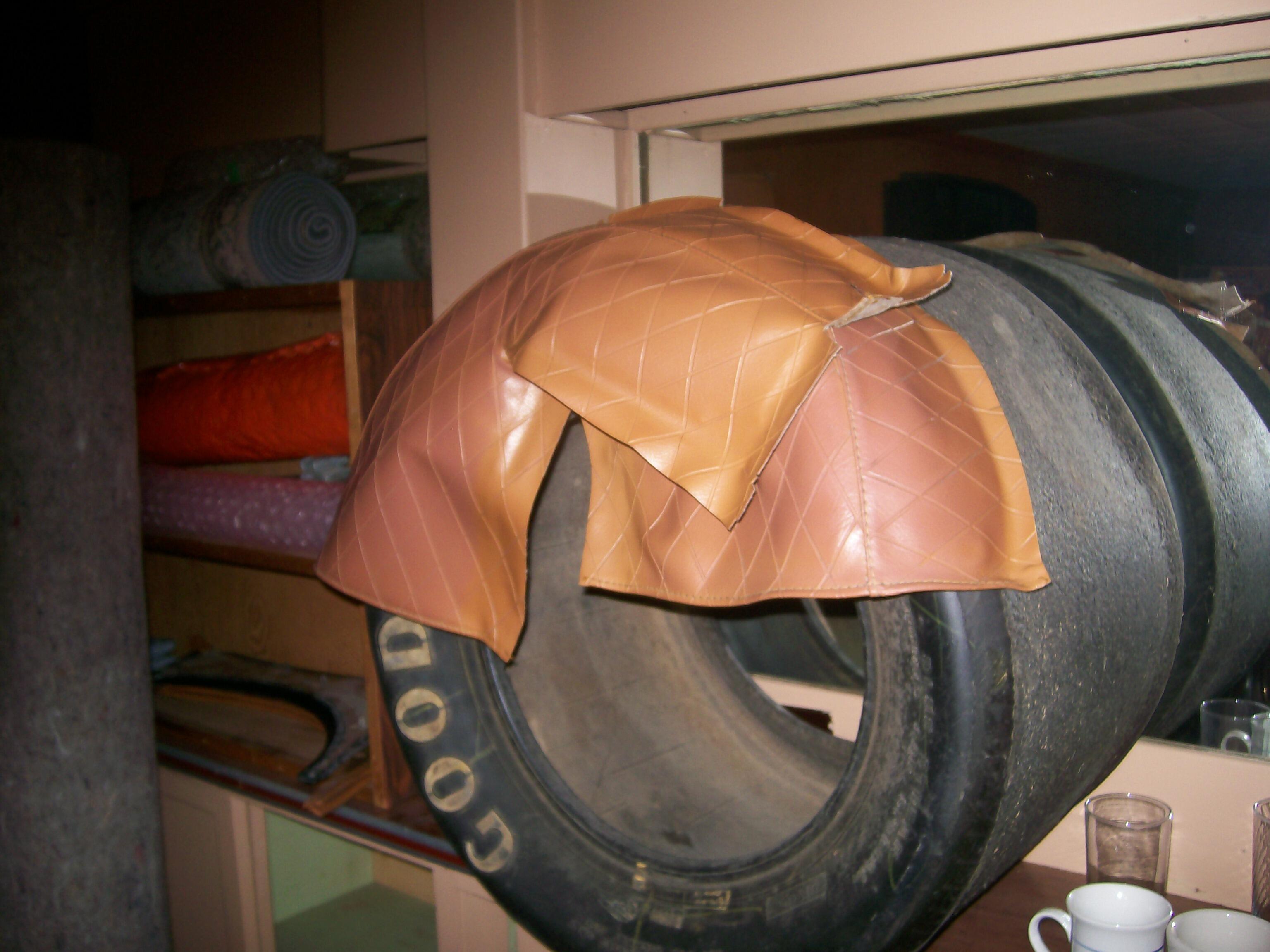
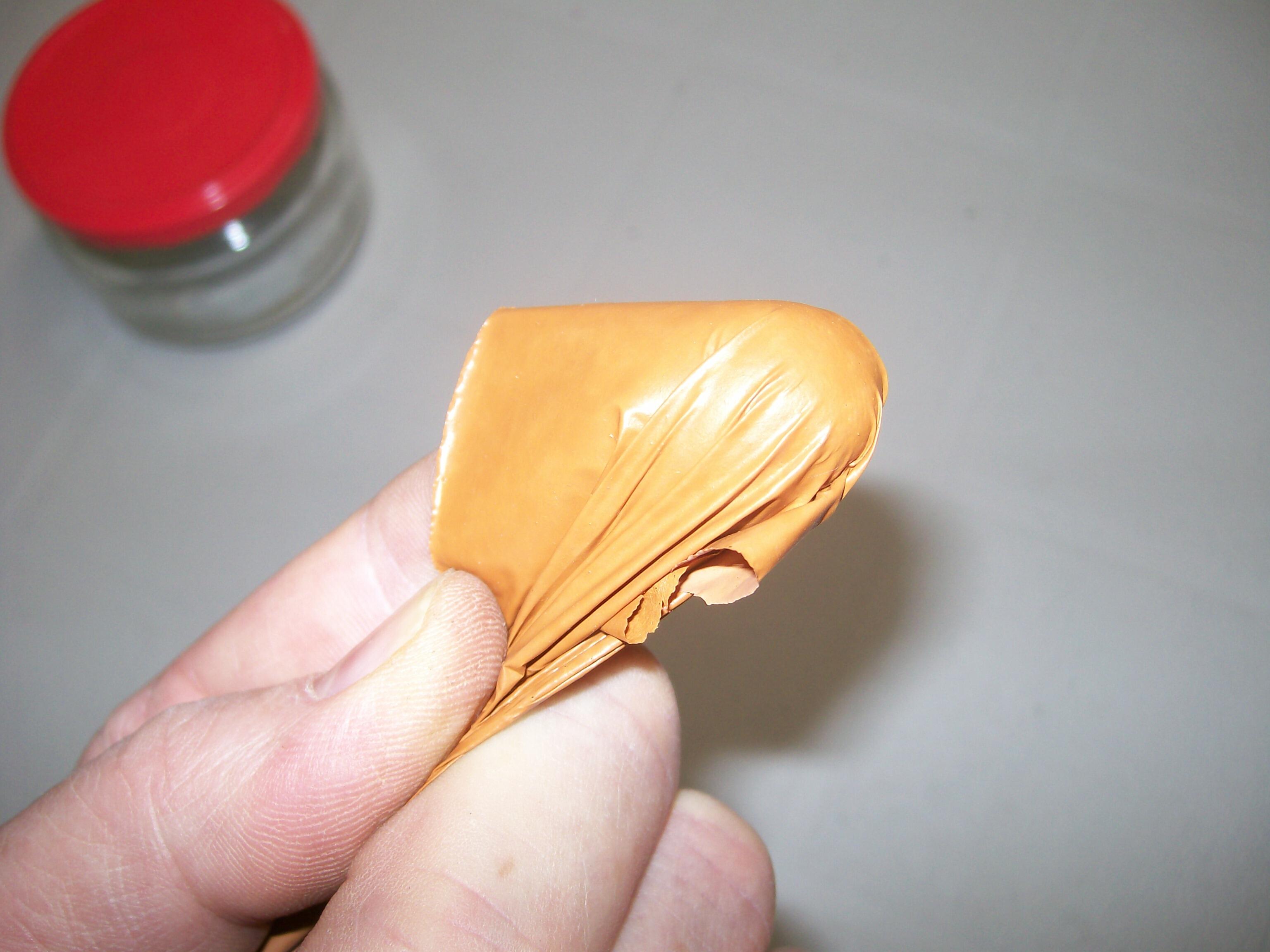
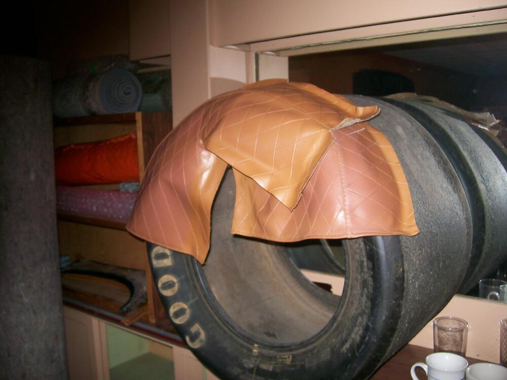
You might also consider using vinyl paint. I used it to re-colour my Z's interior (from black to butterscotch). Pix below should give you an idea of the flexibility and adhesion characteristics (I've seen zero evidence of paint lifting over the ten years since I originally did the application). It sprays on easily using an HVLP gun and doesn't require much in the way of surface prep. It took me three coats to achieve full coverage over the black soft and hard trim pieces. We had a supplier in the Toronto area (Parasol) who would custom mix colors from a customer-supplied paint chip (my results we spot-on, based on a small piece that I snipped from the hem of my new butterscotch seat covers). I expect you'll be able to find a comparable supplier somewhere in the U.S. south-east.

-
$840 (plus shipping) at Motorsport Auto.
-
-
So, exactly how did you get her up on the cubes? Car looks great, BTW. That's a nice shade of yellow. Will you eventually paint the front spoiler to match?
-
That rubber glue may be the least of your problems! I've done a Z dash pad restoration, starting with something that had only 25% of the deterioration that yours has. Even at that, it was a time-consuming job. Not only does the pad surface need to be levelled (not easy to get right, given the multiple contours), it's also necessary to 'V' and then feather-edge all of the cracks so that the filler won't crack along the seams. I'll bet it would take you 20 man-hours of effort (or more) to level, edge-treat, fill, sand, and paint a dash pad like yours to a decent level of final finish. But before you even get started down that road, you'll need to convince yourself that what's left of your original pad has enough structural integrity to prevent the pieces from moving around independently when the cabin temperature goes up or down. With its many full-depth cracks, I don't think I would trust your badly broken-up dash pad to meet that requirement. As a litmus test, it would be interesting to know whether a professional dash restorer like Just Dashes would accept your dash for restoration. Maybe you should send a picture and ask them. IMO, your best path forward will be to either: 1) buy a used dash that offers a better starting point for a DIY restoration (as Siteunseen suggests), or; 2) buy one of the replacement dash pads that have recently become available. In the latter case, you unbolt the old pad from the underlying steel structure (known as the 'armature') and then bolt on the replacement pad. There are a couple of threads on this site that discuss these replacement pads. As a third, lowest-cost/effort alternative, you could just replace your old plastic dash cap with a new one.
-
If, by 'damage', you're referring to the discoloration on the bumper face, it's caused by the fumes from the exhaust.
-
'Make damn sure your sparks are right before you start messing around with the fuel'. Butch Bohunk, Master Mechanic, Finzio's Sincair Service
-
For your possible reference, 1970 FSM Figure BF-3 ('Standard body dimensions') gives these as 331mm and 320mm.
-
Did you clean the bonding surface of the weatherstrip samples with alcohol (or similar) before applying the adhesive?
-
It would be fascinating to know the how Skinner-Union (way back in the middle of the last century) came up with the bendable-tang-with-a-curved-ramp solution for closing the float chamber outlet valve. Maybe they adopted it from the shut-off scheme used in somebody's toilet tank? 😄 It would all be so much easier if there was an adjustment screw. An external screw would be nice, but even an internal screw would be an improvement. I've often wished that someone would do a plot of the geometric relationship of gas level vs needle valve displacement, so that the effects of bending the tang at its fulcrum could be properly understood. One might also take a look at the effects of changing the tang's radius of curvature. Any volunteers?