Namerow
Free Member
-
Joined
-
Last visited
Everything posted by Namerow
-

-
Zedd Findings has always been a quality source of repro parts. Now we have KF Vintage JDM (and I can personally vouch for both their product and their customer service). The (important) surprise is Auto Panel Solutions from Britain. These are previously unobtanium panels that are being delivered a hi-fi by a previously-unknown supplier. RIP, Tabco.
-
No kidding! I'd love to see a picture of the 'factory-authorized tool' that was used for the purpose.
-
I've painted the compartment with the engine in place, but almost everything else had been removed -- wiring harness, intake and exhaust manifolds, and most of the hard lines (only the long fuel/emissions pipes coming in from the trans tunnel remained in place). You'll need a detailing gun to be able to work in the cramped spaces. Certain areas can't be sprayed at the optimum angle. Certain other areas (e.g. bottom of the hood latch bracket) are hard to get paint on at all. You'll need to hold the gun backwards in some places (i.e. pointed toward you). There where a few places where I began to think that an airbrush would have done a better job than the detail gun. Because of the awkward spray angles, you'll get a lot of rough-surface painted areas that will need to be sanded down afterwards to achieve a decent final finish quality. That's a lot of work. I can't see doing this job without removing the intake and exhaust --- and most of the hydraulic lines. Unfortunately, getting those lines off is something that requires a lot of care and patience. Those tiny little 'bolts' used on the clamps are often seized. You do not want to snap one off because there's little to zero chance you'll be able to extract the frozen-in-place remainder. A light-duty hand-held impact driver worked well for me on these little bolts. By the time you get finished, it will probably seem like it would have been a better idea to have just pulled the engine and removed the wiring harness.
-
I wonder what happened to create that big dent in the top of the upper frame? That's thick metal up there. must have been something pretty heavy that fell on it. In one of the active build threads on this site, member said he used a pneumatic 'needle-scaler' attachment to remove the old undercoating. The results looked really good.
-
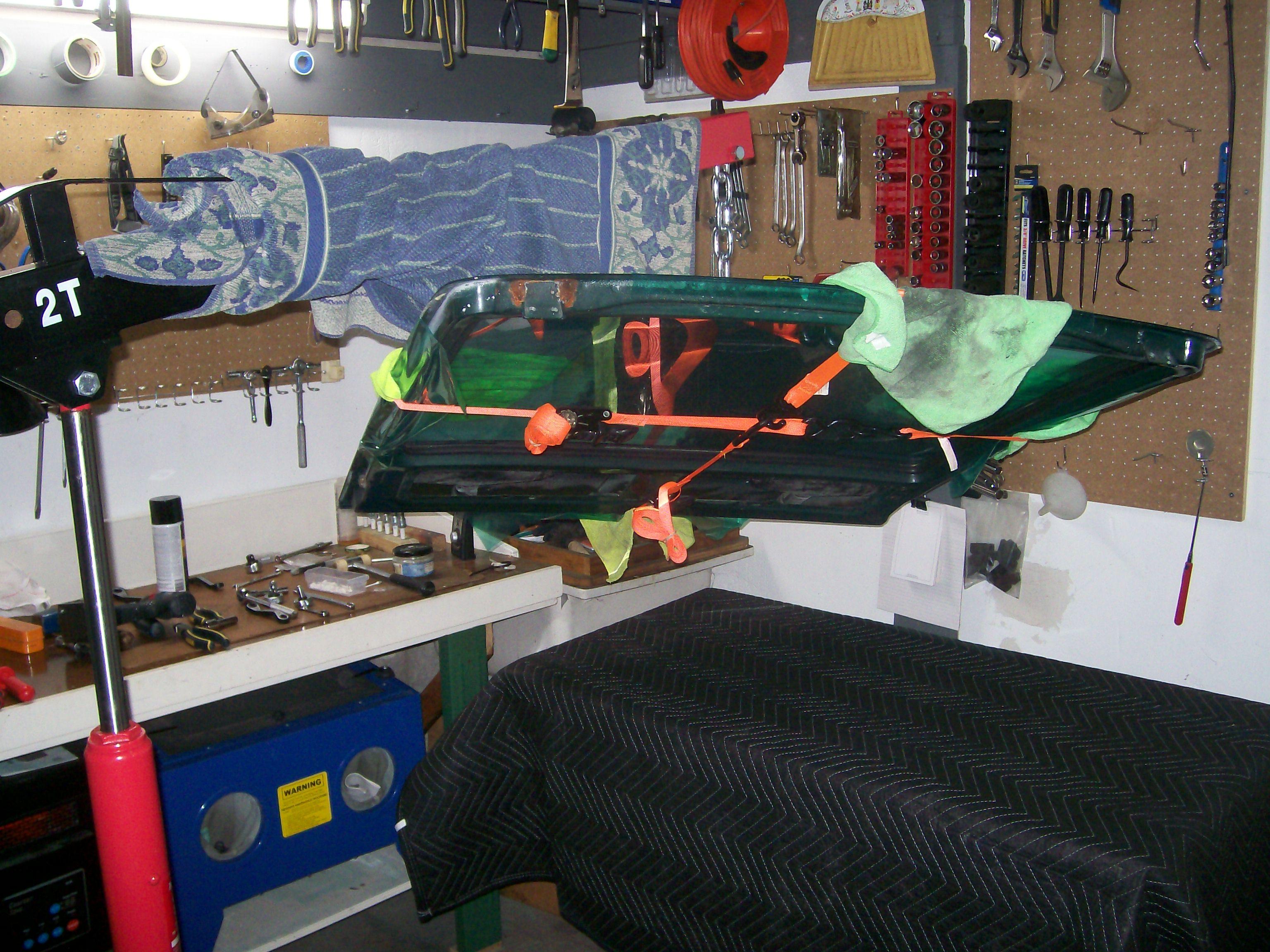
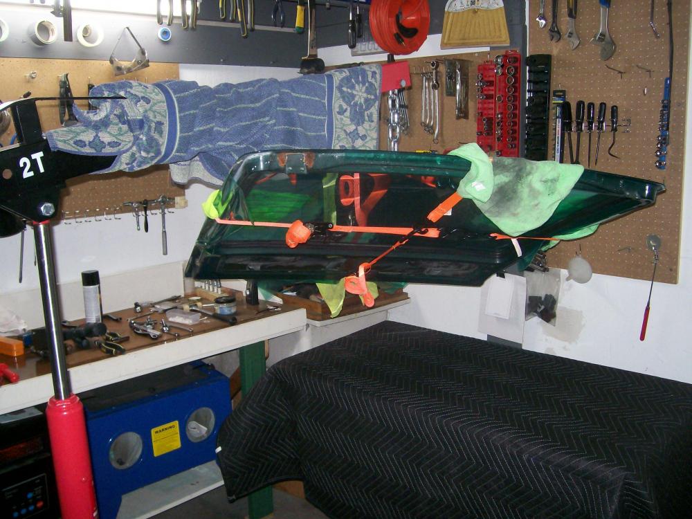
See photo. Engine hoist. Cargo straps. Bath towels wrapped around engine hoist boom arm and hatch to protect hatch paint and glass. With one set of cargo straps centred vertically and another centred horizontally, and using the cross-over point as the lift location, the hatch was pretty well balanced for a flat lift. I trimmed it out by adding small weights (socket wrench sockets) as required on the hatch surface. This wasn't so important during removal, but it was very important during re-installation in order to get the hinge bolt holes to line up.
-
-
I agree completely. And yet, we are dealing with a shift in consumer ethics that had/has no problem with bypassing copyrights to illegally download music and movies and photos. It seems like the transition from physical product (e.g. vinyl record) to digital product (in music, this was iterative: cassette tape to CD to online digital) has made people decide that the product is virtual, so the ownership is virtual/meaningless too. Complicated issue. Early days.
-
Then you're somewhere in between the two views, aren't you? Only the under 35's and the over-65's enjoy the certainties of their views.
-
I agree in general with your proposition. I would replace one word: ""That's is what the scientists should be working on". This nothing to do with scientists. It has everything to do generational politics. If you're under 35, your premise is this: 'I have a career and and a life to pursue and I won't be held back by a virus that statistics tell me is no more dangerous to me than dying of influenza." If you're older than 65, your premise is this: 'I worked hard to get where I am and now my life and my future is being jeopardized by a bunch of careless, selfish younger people who just don't care.'
-
I have read the following tips about using paint strippers: Results can be noticeably accelerated by laying cling-wrap over the treated areas. Using the cling-wrap technique, the best of the modern-formulation automotive strippers will get the job done nicely after an overnight soak. Keep the stripper application away from panel edges and seams (the stripper seeps into gaps and will re-surface later to ruin your paint job). Keep the stripper at least 1-1/2" away from these 'porous' areas. Use good-quality masking tape to protect them. After your final wipe-down of the chemically-stripped zones, remove the masking tape and use sandpaper (power and manual) to remove the remaining paint. For the aforementioned reason, the engine bay surfaces do not look like good candidates for chemical paint stripping.
-
If possible, please mark the photo in Post #32 to show the area where the grinding needs to be done. Based on the earlier pix (Post #28), it looks like you just ground off the weld bead that sits immediately below the perch stamping. Is that sufficient to free up the perch? Just want to be sure I understand this correctly.
-
The Toronto Globe & Mail newspaper recently ran an article in which these high lumber costs were blamed on a pandemic-driven surge in home renovations. Curiously, about a week later the same newspaper ran another article which said that a major mill on the Canadian west coast was temporarily shutting down because of an absence of demand. I drew these apparently conflicting stories to the attention of the newspaper but never got a reply. Thrown into this mix is the longstanding and ongoing battle between Canada and the US over the extent of protective duties imposed by the US on imported Canadian softwood lumber. It's my sense that there's a lot of planted story-telling going on here as part of various parties' attempts to manipulate things to their benefit. Here in central Canada, an 8' length of 2x4 is currently selling for Cdn$6.15 (that's $6.95 tax-in). If you're being charged 32% more than that in Atlantic Canada, it looks like a regional premium (which may depend very heavily on where your regional mills are finding their best market opportunity at the moment -- my guess being the U.S. northeast). SteveJ's report of US$6.00 sounds about the same as your NS pricing (converts to about Cdn $8.00, or Cdn$9.00 tax-in). One local lumber-department price that did catch my attention last weekend was that for a 10' strip of half-round 3/4" molding (plain, unfinished). About Cdn$12.00 !
-
I'm sure others have succeeded at this task. In my case, I used my engine hoist. I wrapped the hatch using HF-quality cargo straps -- one strap along the vertical centreline, the other along the horizontal CL. I used zip-ties at the crossover points so as to make sure that the straps didn't walk under load. Lift cautiously. Study the balance. Watch to ensure that nothing shifts. Make sure in advance that you know where you're going to drop the hatch panel after removing it. A set of movers' blankets is a good idea for protecting the hatch paint once in storage. BTW, I successfully re-installed my hatch (a much bigger challenge, BTW) using the same process in reverse.
-
I also have a shipment from KFVintageJDM on the way. As per your experience, the shipment emanated from Bogota. I, too, have found the company's customer service to be excellent -- fast replies, helpful and on-topic information. Shipping was by way of FedEx and the costs were surprisingly modest. I'm using a USA-to-Canada cross-border trans-shipper service recommended to me by Grannyknot and hope to take delivery at their Toronto drop site sometime next week.
-
One potential issue that I didn't see discussed in the FrostFighter online materials: Is the stick-on grid sufficiently thin*-yet-robust that it will tolerate occasional cleaning of the rear glass surface with glass cleaner? That's one of the strong points of the OEM grids -- they seem to be ok with paper-towel-and-windex cleaning from time to time. (* by 'thin', I mean height above the glass surface)
-
Answer is found at 0:40 in this slightly grainy PPG promo video... https://youtu.be/SdHYcXGx4bw
-
Done with a stencil and a liquid-copper spray would be my guess. Anybody have OEM automotive glass experience?
-
If I'm reading that graph correctly, that would be over six times as many, based on the August numbers. And I don't think the jump in U.S. numbers during July should be misconstrued as the 'second wave'. I think the real second wave is waiting to emerge in October -- and it may not be pretty. Conedodger's story and the accompanying picture are first person and compelling.
-
The Loctite brand used to offer a product specifically for repairing rear window defrost grids. Came in a small glass bottle with a little applicator brush built into the cap.
-
Putting the bodyside mouldings back in place will avoid the need to weld up the mounting holes (probably a couple of hours of shop time). Suggest you consider using steel rivets rather than aluminum, so as to avoid dissimilar-metal corrosion issues. Plain-steel rivets will have their own bare-metal corrosion issues, though. Check to see whether stainless or galvanized types are available. If not, the rivets can be phosphate-dipped to provide at least a degree of corrosion protection.
-
This reminds me of the discussion here a year or two back regarding the clips that hold the Series 1 hatch vent diffusers in place. They were -- and I believe still are -- NLA. One of the CZCC members gathered advance orders from a few other members and then had a batch order made by a local shop. IIRC, the price per piece was nowhere close to $30.
-
So perhaps a new header thread, titled: 'Show Us Your Tubes'
-
Reminds me that one of the foremost names in headers back in the day was 'Hooker'.
-
Way back in 2011, long-time contributor, LeonV, led an informative thread on the topic of headers vs manifold and on exhaust systems (pipe diameters, dual vs single-pipe). The discussion is backed up with dyno test results (note: the quoted Hp numbers are 'road horsepower', so net of all driveline losses -- which typically run at about 10%). The test vehicle was a 260Z that had been retrofitted with a 2.4/E88 engine fitted with triple 40mm Webers and a Datsun Competition header (which I assume is the same as the Nissan Motorsports header just mentioned by Conedodger). Exhaust system theory hasn't changed over the years, so the info in this old thread is still relevant. Included is a video of the dyno test. The car sounds great... although it's informative to listen to the resonance periods as the engine is powered up to max revs.