Namerow
Free Member
-
Joined
-
Last visited
Everything posted by Namerow
-
 My car has a similar but lower VIN than yours, but it does have the valve and the hard line.
 -
What Is a Delfir-chip?
-
Good write-up. Thanks for taking the time. Not much difference in your methodology vs. mine, except for four things: Use of brass wire: Your comment about this making a difference is intriguing (although not intriguing enough to make me drag out all my chemicals to try it out). It would seem to be a matter of net conductivity at the contact point(s) between the wire and the part. I used copper wire (should be better than brass). Not sure that it was a determining factor in the quality of my plating, but seem to have observed a difference with brass vs. 'other' (steel?). Batched jobs I had miserable luck trying to plate multiple pieces at once. Too much difference from one part to another, so lack of reliable way to control for best net result. I adopted an approach of max. 2 parts at a time. Took forever, of course. Current setting Many detailed write-ups on zinc plating specify a current setting based on the immersed surface area of the part(s) being plated. Current set to high = fluffy/flaking zinc over-deposit on the part. Current set too low = long plating times or minimal plating activity. I have a notepad full of surface area calculations. You seem to have gotten away with a 'let 'er rip' approach, by just cranking your power supply up to max and putting as many parts as will comfortably fit on your wire. Is so, I am in awe. Yellow chromate I used Caswell's stuff. Your DIY formula is interesting, but I don't think the yellow chromate dip is the determining factor in the end result. Nor the blue chromate dip. Instead, it's the quality of the zinc plating job that, in my experience, determines the quality of the final finish. The chromate dips embellish a good zinc plating job, but they won't rescue a badly plated part. In fact, they just exaggerate any deficiencies. Zinc I used 'MossBoss' roof flashing. It's an uncoated, thick zinc foil. I lined my electrolyte bucket with it. Although not shown in your photos, it appears that you used Caswell's zinc plate and hung it on one side of your bucket. In theory (emphasis on 'theory'), my approach should be better because it reduces the directional effect. Things we've done the same: muriatic acid dip distilled water dip between every stage of the process Caswell chemicals for the electrolyte bath Caswell brightener added on a regular basis (with notable effect) heated degreaser bath (I used an ammonia/water/TSP solution in a crock pot -- I think you used the Caswell stuff) heated electrolyte bath (I think I ran mine a bit hotter than yours... maybe 100 degrees F) size of electrolyte tank (mine bucket might be about 10% smaller in depth and diameter) The main things I had problem with were: hyper-sensitivity of end results to the prep and cleaning of the parts. Once a part displayed a 'flaw' after initial plating, I had to take it right back to the sandblasting stage to get rid of the problem. Wire-wheeling and acid-dipping wouldn't get rid of it. irregular plating over large surfaces (e.g. timing chain inspection cover) and parts with bends (e.g. brake line clips) inability to get satisfactory results when trying to plate multiple parts in on go
-
And exactly what have you learned, please?
-
Where did you find those ?
-
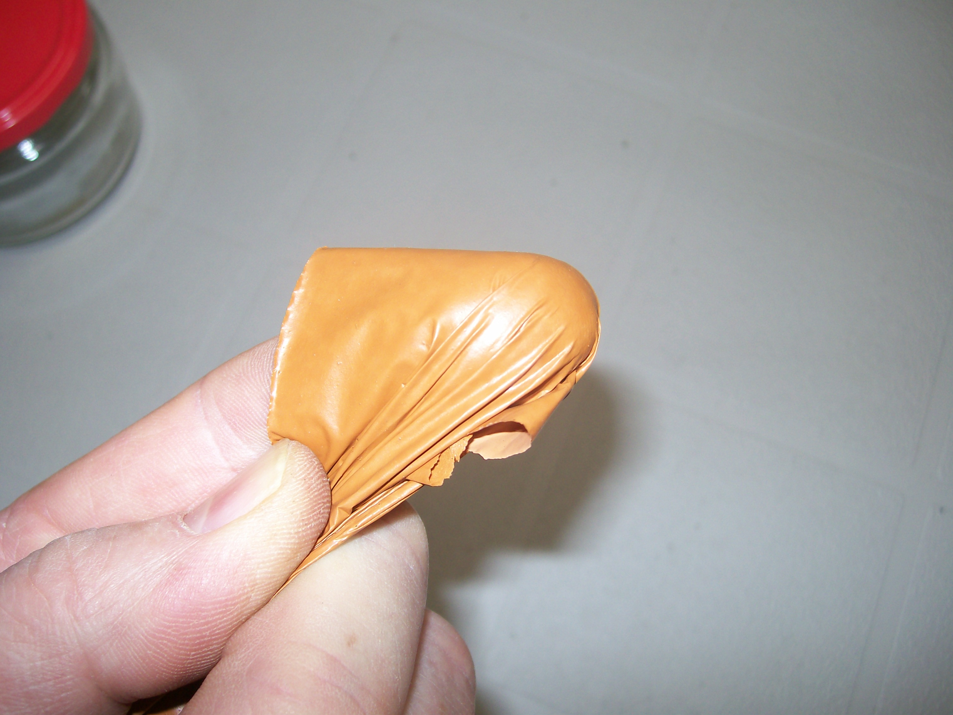
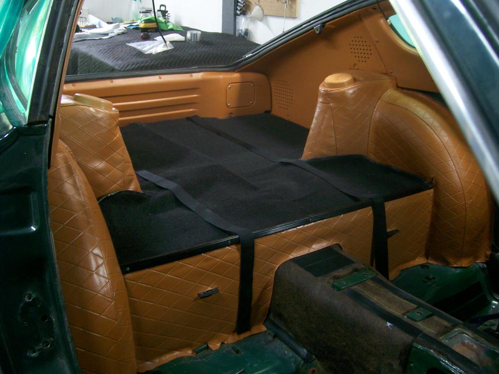
There is a specialty paint supplier based in Toronto -- Parasol Paints ( www.parasolinc.com ) -- who will custom-mix vinyl paint ('dye') to order, based on a material sample or paint chip supplied by the customer. One-week turnaround. I sent them a swatch from the butterscotch seat covers I bought from Banzai Motorworks and found that their color-matching was spot on. This stuff is not what I would call a dye (to me, a dye is something that soaks into a porous surface). Instead, it's some kind of plasticized paint that creates a flexible colored skin that bonds to the substrate. From the can, it has the consistency of water, so its sprays very nicely with an HVLP gun. It begins to set up about 30 minutes after application and is essentially ready for use after 24 hours. It bonds very nicely to both hard plastic and soft vinyl, and -- as others have noted for SEM's rattle-can products -- it's remarkably durable. I've observed no tendency whatsoever for it to lift or peel off. The only application I might be a little hesitant about would be the seats, just because they're subjected to so much stretching and abrasion. Here's a picture of a sample of the paint after curing (I did a test shot on a shiny surface where I knew there wouldn't be a good bond). This was after two or three coats, IIRC. As you can see, the paint is stretchy and very skin-like... x The prep steps are the same as for the SEM products and are well-described on the Parasol website. Different prep chemicals are used for hard plastic vs. soft vinyl, but the same paint is used ('VaraKolor'). The main challenge in the prep is getting all of the ArmorAll-type silicone off the surfaces. The diamond-textured soft vinyl used on the Z is a challenge because it's hard to get all the silicone out of the grooves in the crosshatching. Here are some of the panels and covers after re-installation in my '70 Z. Apologies for indifferent focus (cheap, garage camera). The color register may be a little off, too (varies, depending on whether I'm using the flash or not). BTW, all of the panels and vinyls were originally black... ... x

-
According to the Caswell folks, the orangey-yellow-green irridescent appearance requires a two-step process: 1) dip in blue chromate, followed by; 2) dip in yellow chromate. It worked for me. Actually, I'm kind of partial to the appearance that the blue chromate creates all on its own -- but that's just me. Sorry, I don't have any photos of a part going through the various stages. I just have photos of 'after'. BTW, I tried finishing a part by bypassing the zinc plating altogether and just dipping the part in the yellow chromate bath. It was an unhappy result. The chromate didn't spread evenly across the part's surface. And it didn't adhere very well either. Even after letting the p[art dry for a day, I could wipe the chromate off with a rag. Do not use sugar (or corn syrup) as a brightener. No matter what you read on the internet, it will probably just poison your electrolyte. And it doesn't work. Just pay Mr. Ca$well the money. I have no idea what's in the little bottle they sell, but it sure made a difference for my plating results. Dull grey finish before adding. Shiny silver finish after. Of course, I have no idea what you're using for your electrolyte bath. If it's not based on Caswell's chemicals, then their brightener may not work for you. BTW, I wasted several weekends playing around with a DIY electrolyte made from vinegar and epsom salts. It really didn't work very well, despite meticulous parts cleaning beforehand. So much for all the promising pictures shown by others in their web articles. After a lot of time spent fooling around with plating, I've come to the conclusion that a healthy dose of luck or good karma is required. If you are able to generate good results, I'm happy for you. But if I had it all to do over again, I think I'd just go with a commercial plating shop.
-
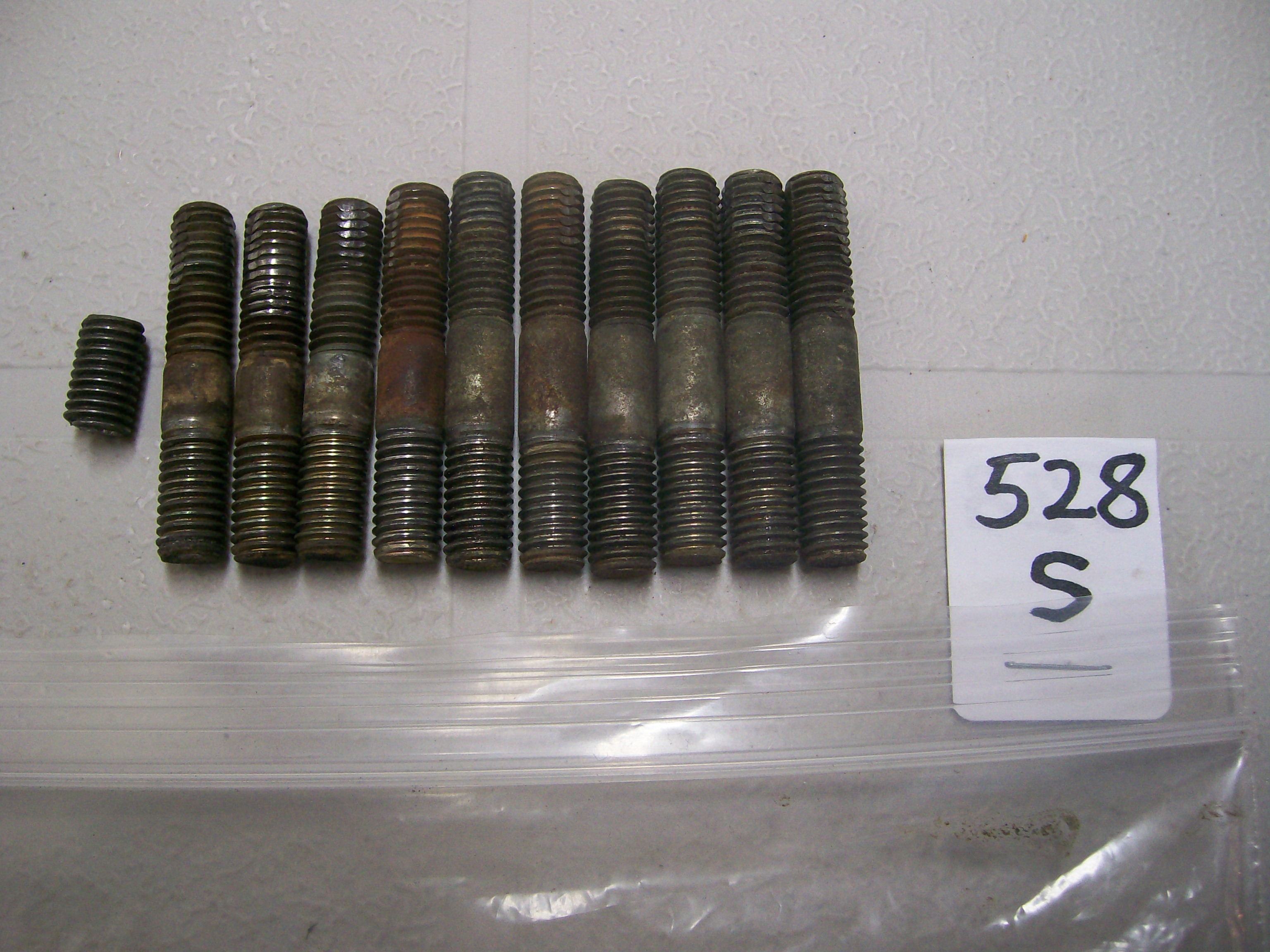
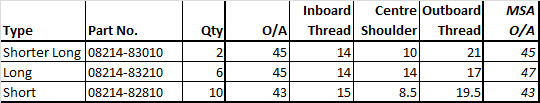
These are the length measurements I've taken (by eye, using a metric ruler) for the Nissan OE studs that came out of my 70 Z's head. The overall length for the studs supplied in MSA's kit is shown on the right... The Nissan OE studs are ground flat on the inboard end (the end that goes into the head), whereas the MSA studs aren't. You can see this in my photos. My 'thread' and 'shoulder' length measurements should be considered +/- 0.5mm, because it's kind of difficult to decide where the threaded-to-unthreaded boundary occurs.
-
I'll measure and post later today.
-
Might be worth getting the long through-bolts re-plated. They like to rust.
-
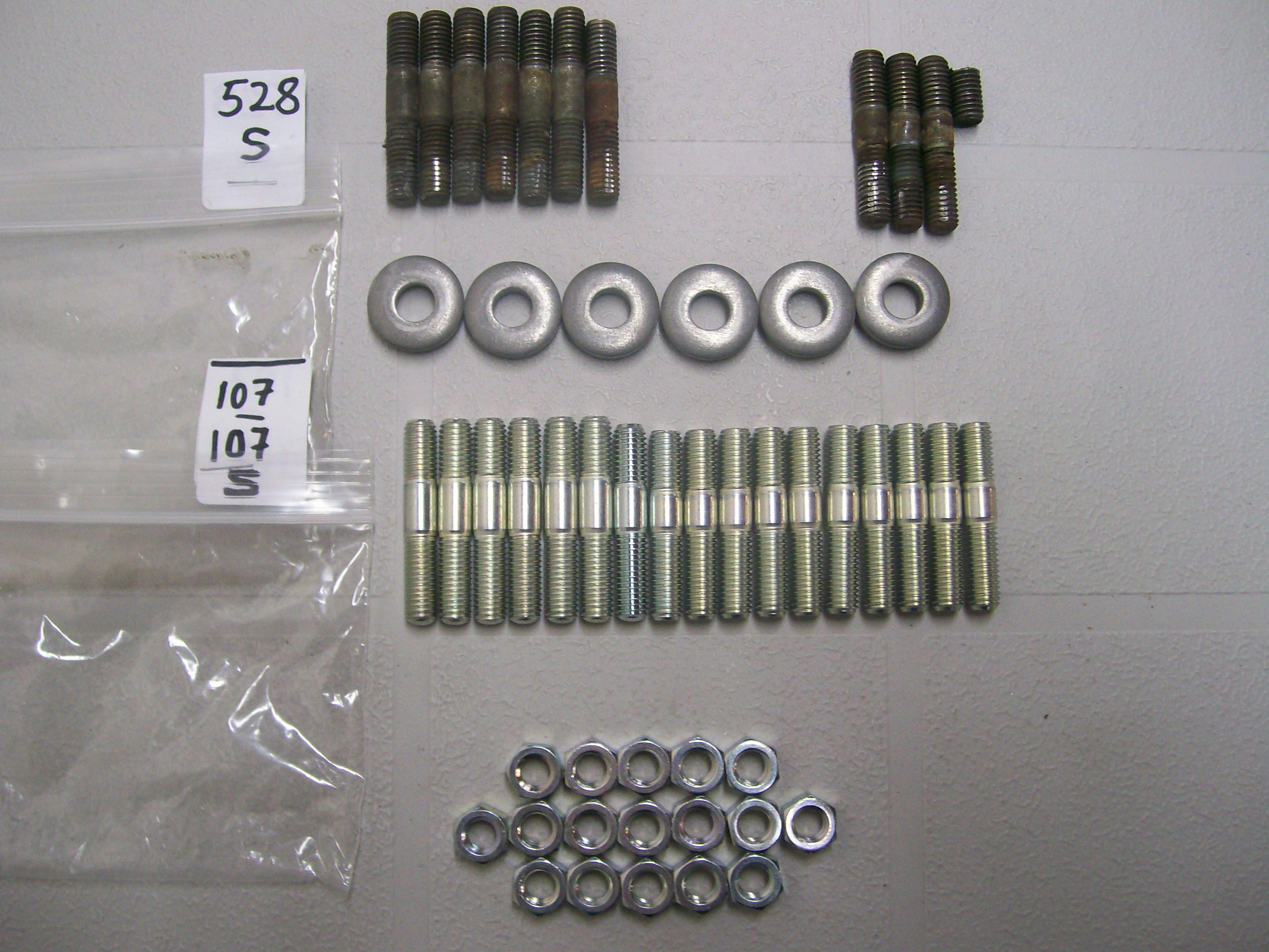
The manifolds are secured by a total of 17 studs (or 11 studs and 6 bolts, depending on which camp you want to be in). The Parts Manual lists them all as studs, but under 3 different PN's (with the related locations vaguely identified in the exploded-view diagram: Type ‘12’ – 08214-82810 - 10 of (short) - includes the top-most row, where my engines have bolts rather than studs. Type ‘13’ – 08214-83010 - 2 of ('shorter long') - one of these is clearly located in the diagram as the rearmost stud where the rear engine 'slinger' (hoist) plate is secured. Type ‘14’ – 08214-83210 - 6 of (long) - used in the locations where the thick 'yoke' washers are used to bridge the flanges of the intake and exhaust manifolds. Notice how the Parts Manual says there are 18 studs. In fact, there are only 17 studs used to secure the manifolds. I'm assuming that one of the Type '13's is used somewhere else. Here's the kit that MSA sells (my original studs are at the top of the photo): Notice the oddball silver stud (the one in the centre - no yellow zinc plating, different overall length from all the others, different length of unthreaded shoulder from all the others. Here's a closer view of my original studs (the snapped-off stud came out of the engine slinger plate location, natch)... A couple of observations: They all have the same threaded length for the end that screws into the head (makes sense, but easy to overlook during re-assembly). The threaded length for the 'engine' end is shorter than that for the 'nut' end, which means that I've got the studs stacked wrong-side up in my photo of the MSA studs. Once again, one of the 'long' studs is a little shorter than the others and has a slightly shorter unthreaded shoulder. In this case I know it was not from the engine slinger location, but unfortunately, I didn't notice the difference in the long studs until I had them all out on the workbench afterwards, so I can't be sure where it came from. It's possible that my snapped-off stud was also a 'short long' type, meaning that these are supposed to be fitted to both the rear-most and the front-most locations. If that's the case, then the MSA kit is technically incorrect by supplying only one of them. I don't think it's going to matter much for the front-most location, but I'm going to definitely fit my single 'short long' stud at the rear-most location to secure the slinger plate (I have a suspicion that it's made from a higher-strength grade of steel than that used for the plated studs). Comments welcomed from any of our veteran or professional L-Series engine rebuilders.


-
That does it! I'm putting the bolts back in the top row. Anybody want to buy six brand-new, never-used MSA studs?
-
Interesting. We now have a statistical population of two. Anyone else with bolts on the top row? BTW, a quick bit of on-line research suggests that studs are preferred over bolts in heavy-duty applications because clamping force is generated without any twisting of the fastener. With a bolt, the clamping force can deteriorate under high, cyclic loads as the bolt loses that twist. It's said that this is important for a cylinder head on a high-boost or high-compression engine working under heavy loads. However, I don't see how it would apply to the case of the Z's intake/exhaust manifold duty cycle. It was pointed out that studs create a different issue. They can be problematic for engine installation and maintenance procedures, because the clamped part (the manifolds in this case) needs enough clearance above/next to it to let the part be lifted over the studs during installation or removal. Unless I've forgotten something, I don't see that being an issue for the L-Series manifolds. So, I'm still puzzled by the apparently intentional mixture of bolts (top row) and studs (all the rest). Hard to believe it would have to do with saving costs (a stud set-up requires 3 parts, a bolt only 2). And I don't see much difference between a bolt and a stud/nut when it comes to wrench access. Maybe somebody in Nissan's Purchasing Department accidentally ordered too many bolts for another application and the Manufacturing people identified the manifolds as a place to get rid of them.
-
"The engine costs €120,000 ($140,490)..." I'm out.
-
To get the right appearance, you're going to need blue chromate, too. And brightener. Lots of brightener. The Canadian Ca$well outlet offers the following: Blue chromate: C$32 (one is prob. enough) Yellow chromate: C$48 (you may need two of these for a large bath) Brightener: C$21 for 4 oz ("Add 1/2 teaspoons per 1.5 gal of plating solution. When plate becomes dull, add another 1/2 teaspoon.") BTW, 4 oz. = 24 tsp, so you may need 2 bottles Factor in tax and shipping, you're looking at about C$150 - 200. I assume you've got your electrolyte bath and zinc and power supply already.
-
Would that fit in a P1800?
-
BTW, 'I do this all the time', and, 'I don't understand why it's such a big deal' are not acceptable responses.
-
No more plating pictures, please, until you show pictures of your set-up and explain your process in detail.. Hurting my self-esteem.
-
I had similar concerns over what I saw with those fat white and white-red wires in my 3xxx 70 Z. Toasted, but not fried. The challenging part is that the wire is rock-hard for about a half-inch inboard from the the connector and there's really no excess wire to let you just lop off the offending section and crimp on a new connector. I've decided to just hold my nose and put in relays as 'triage'. Also, I extracted all of the fuse terminals, c/w wiring, out of my 70 Z's fuse block and re-installed them in a good-condition block salvaged from my old 72. It can be done. Great photos, BTW... but not pretty.
-
Yes. When I said, 'switch contact' I mean 'contact ring'. There is another 'switch contact', of course and that resides inside the Relay. If you cannot quickly locate an exact duplicate of the Horn Relay, why not substitute a standard relay (like the one that you can purchase from any automotive parts supplier)? Someone else here can hopefully guide you on the connections you will need to make. Otherwise, you can consult a local automotive electrical service shop. Also: Before you play with the Relay, be sure that good electrical connections are being made to the Horns at the front of the car. This includes both the POS and NEG connections for both Horns.
-
For the 1970 - 73 models, it should be located on the left-side kick panel, just under the dash ('left' as viewed looking forward). From my notes (copied from someone else's notes): Terminal markings and wire connections at the Relay: B = Battery >> Green/Red wire H = Horn >> Green wire S = Switch >> Green/Black wire The Green wire is the one that is switched internally in the Relay. The Green/Black wire connects back to the Horn Button on the steering wheel. It works by grounding the circuit*. The Green/Red wire supplies power from the battery via the Fuse Box (4th fuse down on the Left side, 10A). (* There is a contact ring located under the Horn button. A wire runs from the contact ring to the front of the steering wheel. When you push the horn button, the front ring makes contact with the steering column, completing the path to ground.) If I had to guess, your problem will be with the switch contacts in the Horn pad and not with the Relay. But you never know. The attached wiring diagram (in colour!) was created a few years back by a gentleman named Sully Ridout and contributed to this site. It's appropriate to the 1972 N. American models, so it may not be exactly right for a European Z (other member located in Europe can probably comment). However, it may help you to figure things out for the horn circuit at least. S30 Wiring Schematic - 72 240Z - Colour (by Sully Ridout).pdf
-
-
If you buy a remanufactured unit, inspect it carefully before you leave the store. At least one member here (Grannyknot) reported that his remanufactured MasterVac showed damage to some of the 'teeth' on the lip of the housing (probably from poor handling during disassembly at the rebuild shop), to the point where he had concerns about its vacuum integrity. I think one of the threaded studs was marginal, too.
-
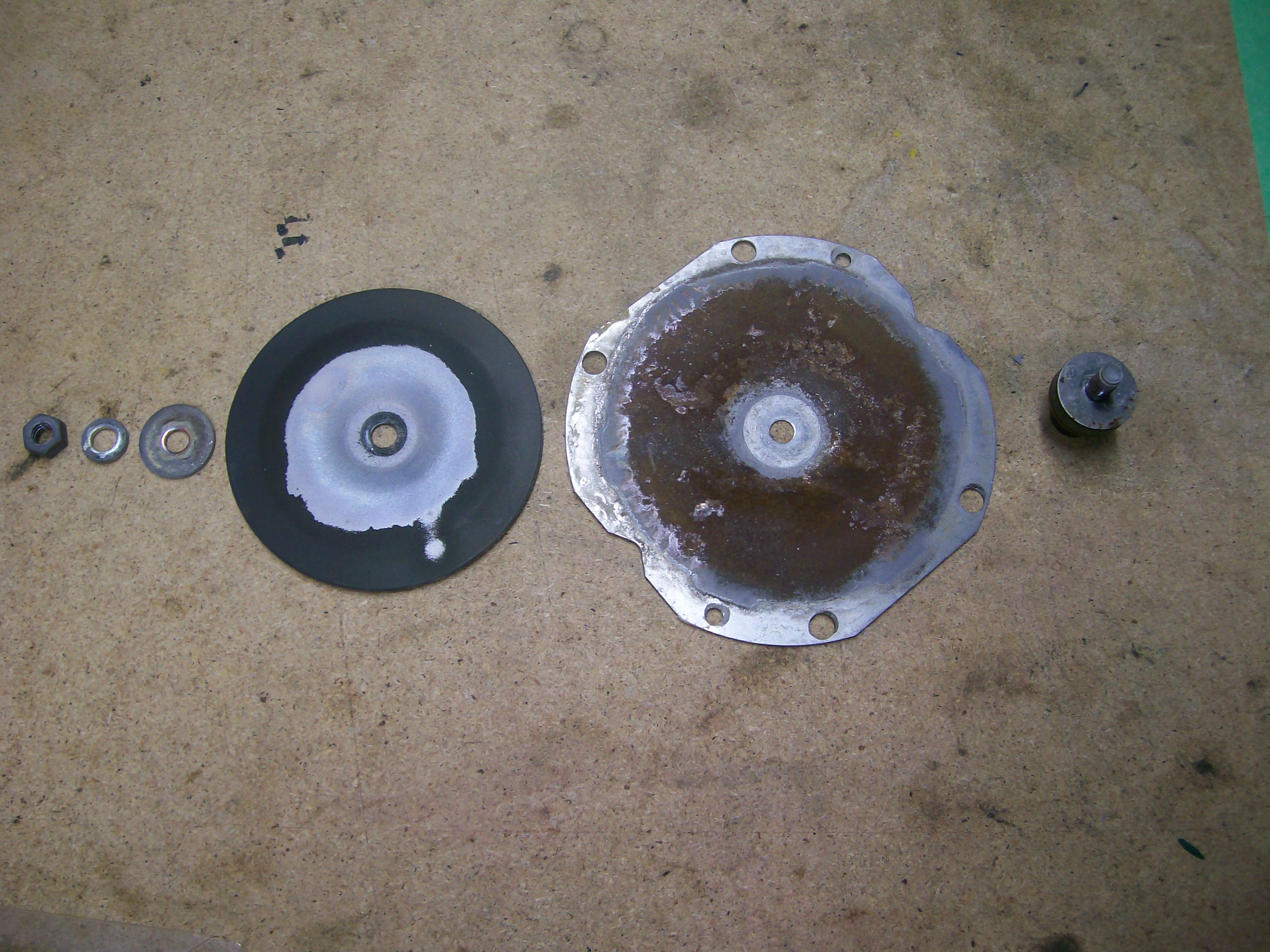
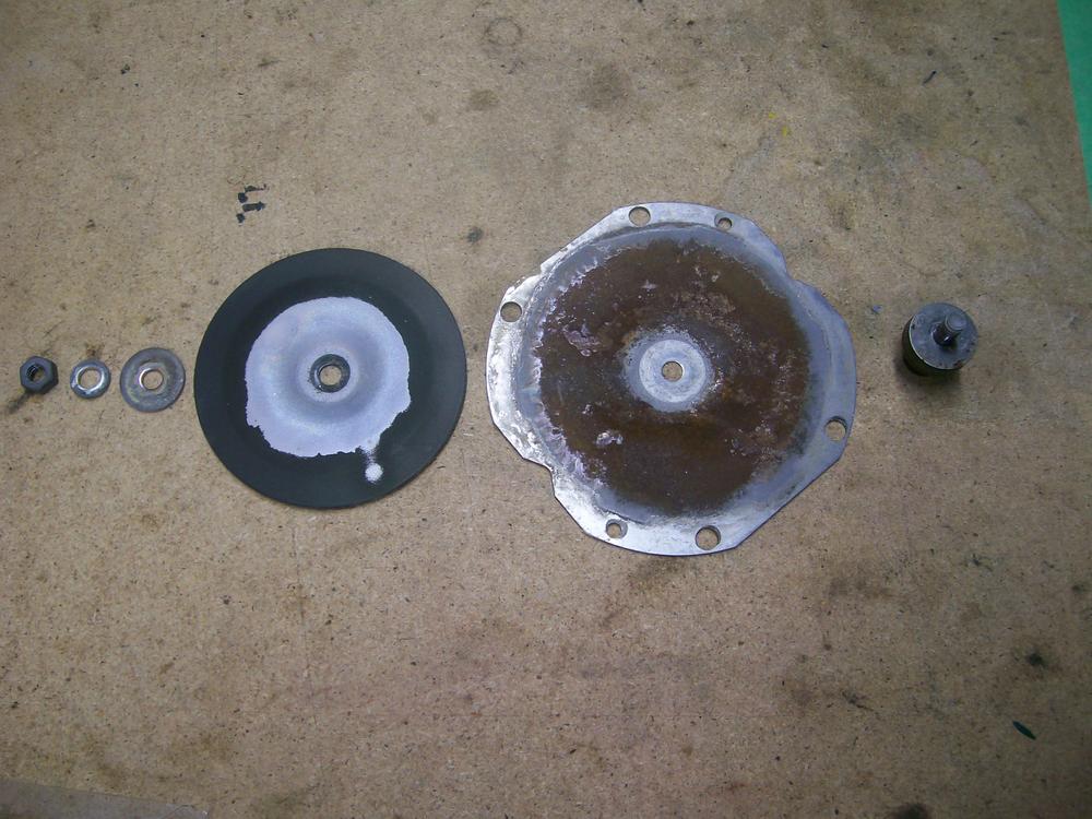
... or make your own gaskets. I made mine using butcher's paper. About the right thickness and somewhat waterproof. Zup's successful experience using no gaskets at all suggests that they contribute nothing to the acoustic performance, so maybe they were intended to be a moisture seal (albeit, not very effective -- see picture). So maybe a thin bead of silicone gasket material on each mating face would be the easiest and most effective solution. If, for any reason, the sealant snubs the sound output, you can always strip it off and try something else.
-
Serendipity, my friend. I remember the' authoratative' blast of my distinctly non-USA, two-tone Z horns delivered when I was a 1970's driver . When I rebuilt the horns from my 70 Z, I was shocked (as in underwhelmed) by what I heard. I love the nostalgia effect, but for the guerilla driving conditions where I now live, they need modern-tech, hi-volume reinforcement.