Namerow
Free Member
-
Joined
-
Last visited
Everything posted by Namerow
-
 I got the idea from our friends at Z-Therapy, who say: "After the bodies are machined, the carbs get polished. All ZTherapy carbs are machine polished with a unique high pressure (22 G's of force) machine polish technique. This is not a wheel polish. These carbs shine better than when they came out of the molds. By polishing in this way, we close the pores of the metal. They shed dirt better, and look great!" Maybe they really are using a shot-peening process?
 -
In the 1990's there used to be a guy, just north of Salt Lake City IIRC, with a big yard full of Z's. Fifty or more. Same story. He would let the odd person in to have a look, but he believed that he was sitting on a gold mine and refused to consider realistic offers. Maybe this is his nephew!
-
-
There's been a bit of chatter over the last couple of days about positive results achieved with a needle scaler tool for the removal of tar-pad sound dampener from floor panels, and even undercoating from the car's underside surfaces. That's great information and looks the a a heck of ot more convenient than dry ice, CO2 blasting, scrapers, blow torches and heat guns! However, I'm interested in hearing about the use of this tool for cleaning and conditioning aluminum castings. I'm thinking specifically of the Z's valve cover and SU carb bells. In both cases, the parts don't lend themselves to blast cabinet treatment (because of the size of the part size in one case, and because of the risk of media-particle part contamination in the other). In addition, the end result from blasting these parts isn't necessarily a correct look -- to my eye, anyway (it's a little too bright and porous-looking). I think I recall someone saying that a needle scaler delivers a more OE look for these types of castings (a smooth, 'hardened' surface look, kind of like shot-peening at a miniature scale). Has anyone tried this? Any before/after (or even just 'after') pix to share?
-
-
Thanks, Jim. Chris, I believe that the path forward is clear. Grab one for me and I'll pay you when I pick up my part of our MSA order (assuming that they ever get around to shipping it, of course ).
-
The Ontario distributor, JR Power Products, is apparently this guy: Jack Langen (905) 880-9976 15650 The Gore Rd Palgrave ON L0N1P0 Chris, I believe that address is within shooting distance of your place. Apparently Langen is an old-school hot rodder and used to sell the stuff at shows and meets. Why not check him out to see whether he has any Gibbs on hand? If he does, grab a can for me, too.
-
Sign me up for a can, too. You can never have enough 'wonder chemicals' on the shelf.
-
See my post elsewhere on using modeler's chrome foil to refresh these details.
-
Diseazd: Looking at the photos once again, I think you've nailed the stance perfectly on this white car. Can you please advise on how you got it there... spring & shock set-up? tire size? wheels? (esp. offset) anything else done to affect (or allow) the ride height? Also: What type of chin spoiler is this car wearing?
-
Didn't realize the replacement fender had rust, too!
-
Good refresher for me, too, because I had nothing in my notes to back up the 'double (not bubble)' comment and all the usual Z-car references (FSM, Wick Humble, etc) seem to overlook this point. Good luck with the 'flailing machine' (sorry, Travel'n Man. I couldn't resist )
-
Good refresher for me, too, because I had nothing in my notes to back up the 'double (not bubble)' comment and all the usual Z-car references (FSM, Wick Humble, etc) seem to overlook this point. Good luck with the 'flailing machine' (sorry, Travel'n Man. I couldn't resist )
-
RIP... 'Rust In Pieces'
-
My notes say, 'double (not bubble)'. A better point of reference, though, may be the chart (with photos) that appears on the FedHill website: http://www.fedhillusa.com/webnuts/common flares6.pdf Note in particular the picture with caption that reads, "10mm x 1.0 Asian nut with SAE/double Flare". Now, compare that with the picture immediately below with the caption, "10mm x 1.0 metric nut with DIN/ISO flare" From these pictures, it looks like the best way to visually detect the difference between the two is to look at the flare from the side and check the contour of the back/bottom side of the flare (rather than the front/top side). The back side of the DIN bubble flare is almost flat/square. The back side of the SAE double flare is tapered (45 degree angle).
-
As a footnote to Grannyknot's discussion, I would add that there seems to be some magic temperature that you need to hit before the corrosion bond along the length of the threads will break down. It's been my experience that a regular propane torch may not be able to get the job done -- especially when you're dealing with a huge heat sink in the form of the cylinder head. Try MAPP gas instead. An oxyacetylene torch would be ideal (but then, I don't have one and you probably don't either). I like the MIG/welded-on-nut strategy because of the massive amount of localized heat that it puts directly into the threaded piece. However, even a cheap MIG is going be an expensive solution here... unless you can borrow or rent one. For reference, I wrestled for days with a snapped off bolt (a measly little 6mm guy) that was stuck in a distributor mount casting. I tried everything, including alternating heat heat from a propane torch ('swirl' type head) with spray applications of 'liquid freeze', followed by light blows with a hand-held impact wrench (I was using a Crafstman ez-out). I had let the casting soak in penetrating oil (acetone-ATF mix) for a week before I got started with the torch. I never got the stud to shift even a tiny bit. I then tried to carefully drill out the core of the stud so that I could pull the thread remnants out of the hole, but the corrosion bond was still so bad that when I pulled on the thread curl, it would just snap off. I had to run a thread tap through the hole to chase out the remnants and even that wasn't a happy process. In the end, I had to drill out the hole and install a threaded insert. Message: That steel-to-aluminum corrosion bond can sometimes be really strong.
-
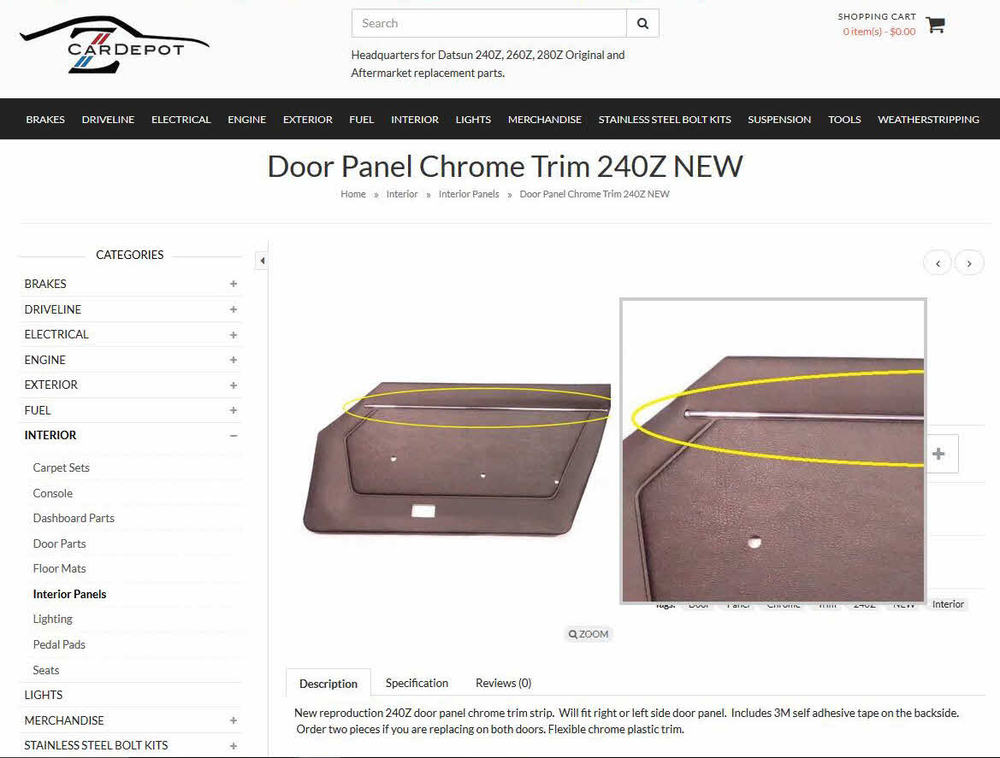
Has anybody tried these? Are they any different from the generic moulded-vinyl stick-on strips available at parts stores? Since the original accent strip is heat-embossed to the door card vinyl and thus not removable, I'm having difficulty visualizing how that kind of stick-on strip (has a flat mounting surface) can be installed on top of the original strip without it sitting way too high. I'm hoping that these might, instead, have a 'U' cross-section so that they fit as a cap over the original strip.
-
Sorry. Double post.
-
Personally, I'd go with the SS kit. A little spendy at US$300, but so much less work and hassle. Also, you won't have to worry about finessing the lines to get them straight. Or getting the bends at the right places so that the lines fit the body and the mounts. And you won't need to get into discussions about how to get a rental flaring tool back and forth across the border. Note, too, that a good 'bubble' flaring tool and a tubing straightener are going to cost you US $350 (plus tax plus shipping plus brokerage fee plus duty), so that US$40 roll of cunifer tubing -- which I really like, by the way -- may not be so economical as it first seems. Classic Tube is in Lancaster, NY (see: Buffalo Airport, Lancaster Speedway, etc). You could drive down, take in a Bills or Sabres game, have some wings and Big Ditch beer, and with any luck get waived through on the duty on your way back home. In addition, there's a new Princess Auto outlet in St. Catharines that you can check out on the return trip. BTW, if you go the pick-up-in-person route, the $$$ you save in courier delivery costs will more than pay for your gas. Heck, it might even pay for the game ticket and the wings and beer!
-
When Steve makes a new batch, this grommet may solve your exposed paint issues... http://www.240zrubberparts.com/apps/webstore/products/show/6517164
-
You make a good point about getting the 'curl' of the wire correct for each of the four functions. I can see why you've ended up with stiff action. Go back and take a look at the 'floor' photo of my finished levers-and-cables assembly. I curled the new wires so that they matched the shape of originals as they came out of the car (notice that one of the wires actually has a double curvature). To put a curl in the (tempered) wire, clamp a piece of 1"-dia pipe or dowel vertically in your bench vise and then pull the wire back and forth across the round surface with a bit of 'pull'. You'll need to grip each end of the wire with vise-grips so that it doesn't twist in your hands as you're doing the forming. It doesn't take much, so be careful not to over do it (takes a bit of practice --- but you've now got lots of wire to play around with!). Put the curl in the wire first. When you're happy with that, you can now form the 'step' at the end that goes into the control lever hole (as you point out, this requires paying attention to the alignment). As the final step, cut the wire to approx. length at the other (straight) end. Cut it a bit long, just in case. Same goes for your sheathing.
-
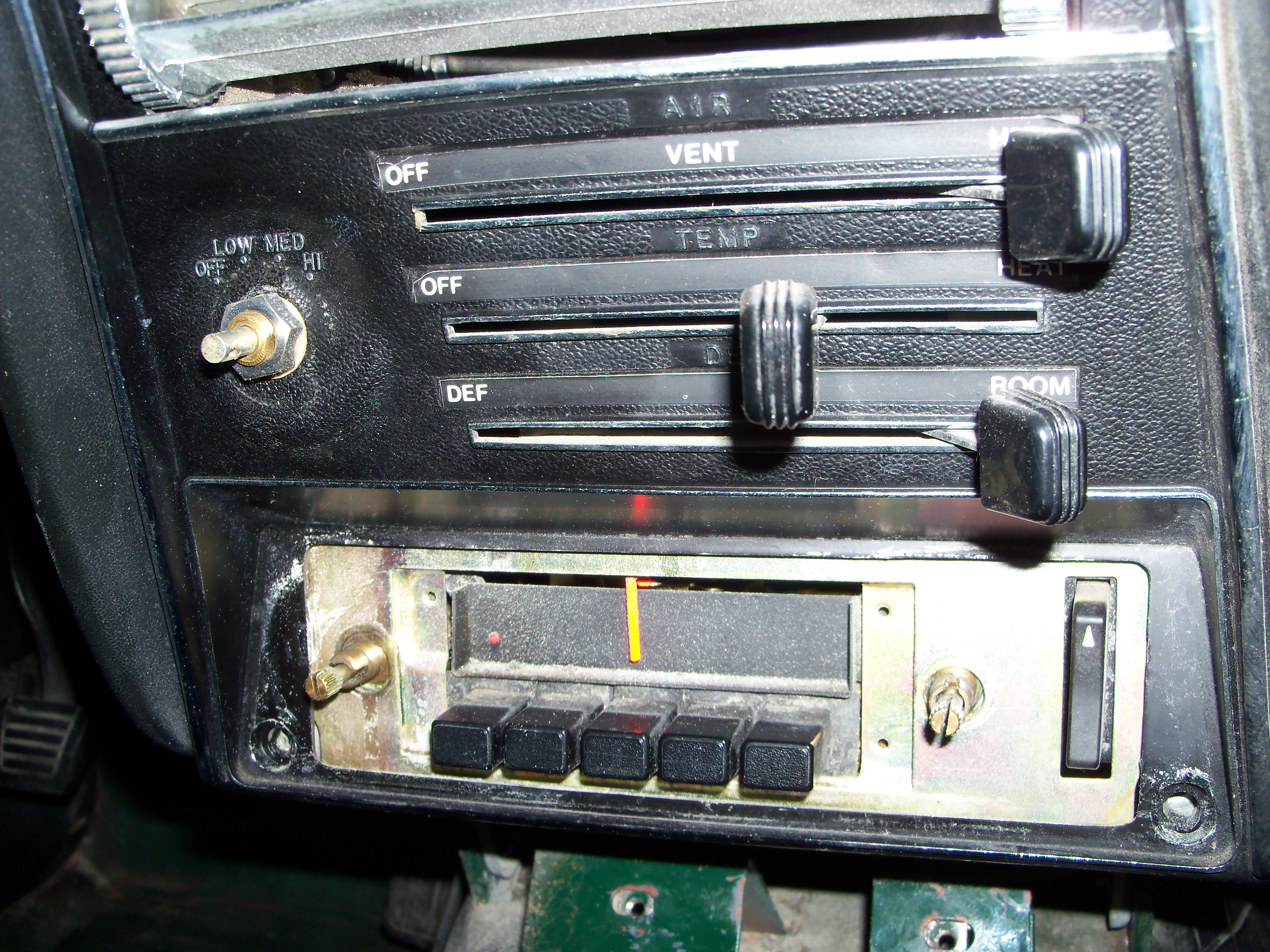
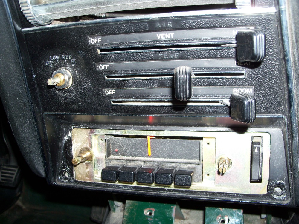
This photo, taken while I was removing the radio from my 70 Z, should solve the mystery...
-
I agree that the D-I-Y strategy could come with a lot of hidden costs. It depends on the level of skill and equipment you're starting from. If you can provide the correct-sized plastic bushings, I'll bet you could get this work done quite successfully by a local machine shop for $200 - $250. If you follow this route, you'll also need to find a supplier of correct-spec replacement throttle shafts. If you check out some of your country's marque clubs, you may find someone local who does this work on a hobby-business basis (like the guy who did the on-line feature that you posted the link for). Here in the Toronto, Canada area, I know of at least two guys who provide SU re-bushing services as a hobby business (and at least one of them installs sealed roller bearings rather than bushes). If you go with the well-respected Z-Therapy in the USA, you may want to consider just keeping your existing carbs and paying them the $200 core charge (you'll see why in a minute). This would result in an out-the-door price of $880, if I've read Z-Therapy's pricing chart correctly. Now you have to look at shipping costs. Z-Therapy's website says that they only ship internationally by way of US Postal Service . It appears from the USPS website that the largest USPS 'flat-rate' box won't work (12" x 12" x 5.5"). You'd have to go with an oversize, non-standard box. Assuming a box that measures 24" x 12" x 12" and assuming a shipped weight of 5 pounds (~ 2kg), the USPS online calculator generates a price of $73.80 for their 'economy' delivery service to Germany. Unfortunately, the fine print for shipments to Germany says that any shipment valued at over $300 requires paperwork from the shipper (meaning that the value of $900 will need to be officially declared by the Z-Therapy). Later, it says that: " Germany will not accept any Priority Mail Express International or Priority Mail International insured item valued at more than $500. Items valued at more than $500 will be returned to sender. " So you would have to use the USPS premium 'Global Express Guaranteed' service (3-day delivery). For this service, the USPS online calculator generates a base shipping price of $195 for the same 24" x 12" x 12" / 5-pound box. Add at least $10 for insurance. Note that I didn't read all the fine print associated with this type of service. You should. Z-Therapy will probably add a markup to the USPS shipping cost to cover their in-house packaging and handling costs. I'm going to guess that might be $50. You'll need to confirm this with them. When the USPS package arrives in Germany, you'll have to pay customs duties (I'm going to guess 10% on $880) and perhaps/probably your national VAT too (another guess: 15%). You'll also be paying the hidden costs that your credit card vendor builds into the transaction by way of skewed currency exchange rates. Add another 2.5% to the ($880 + $195 +$50) shipped price. Call it $25. So: If my estimates are reasonably correct and I got my math right, it's going to cost you about US$1,400 to have a pair of Z-Therapy Hitachi-SU's delivered to your local post office outlet and with all local customs/sales taxes paid.
-
The author of that linked re-build article really takes SU to task for the use of a brass shaft with brass bearings. The Hitachi-SU's in the Z use chrome-plated throttle shafts. Good idea... but they still wear (first the chrome plating wears off the shaft, then the shaft itself starts to wear). The load on the shaft generated by air-pressure loading on the throttle plate under closed and part-throttle conditions must be huge. There should be little difficulty in finding a source for appropriate bushes or bearings. For inspiration, have a look at the Boston Gear catalogue, using this link: http://www.bostongear.com/products/bearings/molded.html Note that some SU carb rebuilders replace the OE bushes with seal-equipped roller bearings. Others (like your author) replace them with either new bronze bushes (oil-impregnated type preferred... ref. 'Oilite') or with an engineered plastic (like Delrin). If you decide to go with plastic, make sure the type you use is gasoline and ethanol-resistant. The roller bearing strategy is claimed to provide smoother action coming off Idle (where the plate and shaft loading is highest) -- and it undoubtedly does. How much so, I can't say. You'd need to ask people who've experienced both the bushing set-up and the bearing set-up, back-to-back.
-
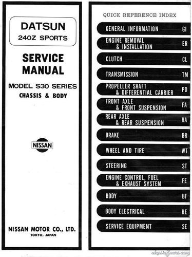 This is a great post by CanTechZ. Almost as good as having the real thing in print version. Actually, maybe better -- this .pdf is so clear that it can probably be optically scanned to generate searchable text.
- 3 comments
- 1 review