Namerow
-
Posts
1,483 -
Joined
-
Last visited
-
Days Won
23
Content Type
Profiles
Knowledge Base
Zcar Wiki
Forums
Gallery
Events
Downloads
Store
Blogs
Collections
Classifieds
Everything posted by Namerow
-
Not sure what wiring diagram you're looking at. None of the versions I've seen make a specific call-out of the wiring colours at the dimmer rheostat. It seems obvious that the wire on the right (in the wiring diagram) is RL, but the diagram leaves it for you to guess at the colour of the wire on the left. Anyway, the wiring on the rheostat from my '70 is intact. Both wires are RL. In your #1 photo, you have one wire intact, located at the 3:00 o'clock position. It has a male spade connector at its loose end. The one that's snapped off belongs on the terminal located at the 5:00 o'clock position. This one has a female spade connector at the loose end, c/w the usual clear plastic shield. Both wires are the same length. If you're going to try to fix your dimmer rather than jump it, you'll need to clean the wiper and resistor coil with De-Oxit. Then put a light smear of dieletric grease on the rubbing surface of the resistor coil. Finish with a tiny drop of light oil in the control shaft bushing and you should be good to go. Mine works ok, except for an annoying dead spot over the 30% - 50% part of the control range.
-
 Bonzi Lon's comment about watchmakers using this technique got my attention, so I did a little internet searching and came up with a site dedicated to watchmakers. http://mb.nawcc.org/showthread.php?94417-Removing-broken-screws-with-Alum-bath&s=9a54a148536c988626245b769919efd8 Here's a good summary comment from one of their members: "Alum is pretty danged safe stuff, and one of the safer things to get steel out of brass or aluminum. In other uses, it's used in heavily-silted water to flocculate (clump) the silt so it'll settle, and it also disinfects the water somewhat. My uncle used it to treat his tan-colored well water way up in the Colorado Rockies; a few cupfuls of alum would clear up 350 gallons (over 1000 liters) in a couple of days. It made the water taste a bit funny-sweet, but was perfectly safe. It's also used to make pickles crisper. It's the active ingredient in a styptic stick (used to clot shaving nicks). As people have said before, it works far faster at removing steel leftovers if it's hot. (WARNING! Don't use a steel pan or can to do this in - it'll eat that, too! Stainless isn't as reactive, but just use glass (Pyrex or its equivalent) or an aluminum pan, ok?) Bring some water to a simmer, and dissolve as much alum in it as will dissolve (saturated solution), toss in the brass or aluminum doohickey with the steel whatzis in it, leave it at or just below a simmer, and come back in "a while" to no more whatzis. It'll still work at room temperature (if you don't want a glass thing on a cooktop, always a valid concern), but it'll take longer (like overnight). The alum reacts with the iron, but not the aluminum or the brass. <geek> According to the chemistry book, it has to do with the trivalent nature of iron (which doesn't exist in copper or zinc). It starts out full of aluminum ions (which are also trivalent), so no reaction there. </geek> The stink is from the sulfates being ionized and released. If you inhaled enough of it, you'd eventually have a tiny fraction of the the sulfates bond with the water in your mucosal membranes to form a mild sulfuric acid, but your body will make you leave waaay before it comes close to doing any damage. In other words, don't stand and force yourself to snort the fumes, but don't break out the hazmat gear, either. Trust your nose to tell you when enough is enough. Use common sense." It's evident from the rest of the thread on that site that the alum technique is well known and proven effective -- at least, effective on tiny watch parts. A couple of commenters there speculate that it's especially effective on the threaded areas of a steel bolt -- and that may be true, although probably just because the liquid can penetrate along the threads, where it has a very large steel surface to work on (compared to just the head of the stud). In general, the watchmaker site commentary expresses full confidence in the safety of this technique for use with steel-in-bronze and steel-in-copper, but nobody steps right up and says they've used it successfully for steel-in-aluminum. We'll have to wait to see how it does on a a quarter-inch worth of snapped-off 6mm bolt in my aluminum casting.
 -
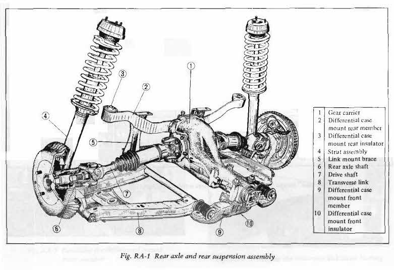
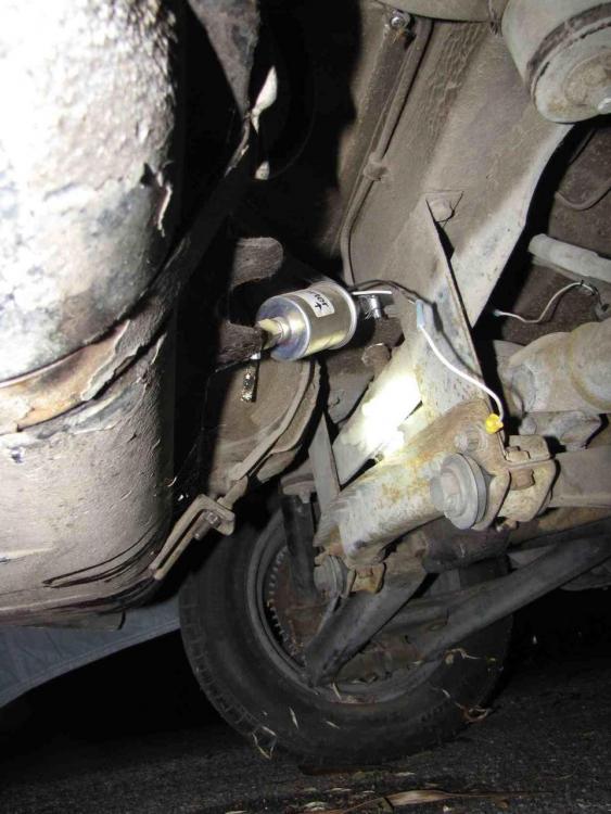
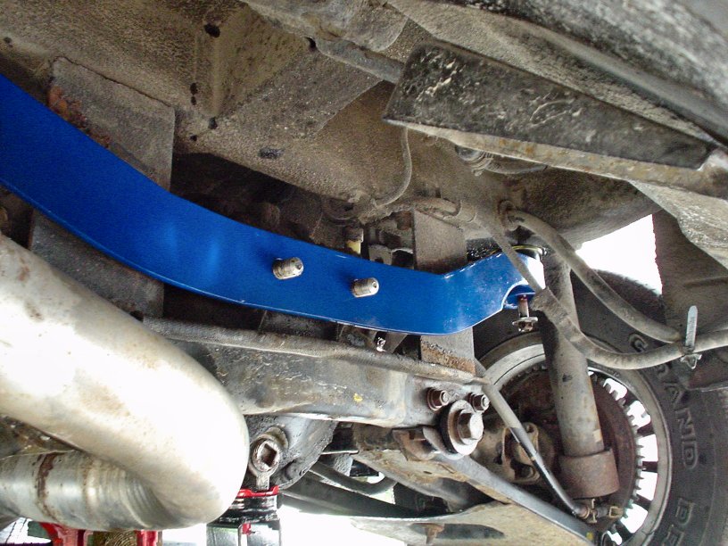
I've been looking at pictures and scratching my head over this. Maybe someone can solves the puzzle for me... I think everybody knows that the design of the S30's moustache bar (MB) was changed from the original 'flat' version to a new 'curved' version at the beginning of MY-72. This was part of the re-design done by Nissan to re-locate the diff further to the rear so that the halfshafts would no longer need to operate at a 5 degree fore-aft angle. The 71 and 72 FSM's both use the same diagram of the Diff/Rear Suspension (see below). It shows the MB mounted with its end loops sitting on the front side of the bar. The MB is shaped so that it 'droops' down from the body. That droop means that the MB can't be mounted 'upside down'. If you're going to flip it (for whatever reason), it only be 'flipped' around its vertical centre axis, so that the MB will now mount with its end loops sitting on the rear side of the bar. Note also that the diagram from the 72 FSM shows the MB sitting in front of the hanging vertical brackets for the lower diff crossmember. Now look at the smaller diagram, taken from the 75 (280Z) FSM. It shows the MB mounted so that end loops are positioned on the rear side of the bar. Why? What happened to the rest of the drivetrain design to force this change of mounting orientation for the MB? And is the MB for the 280Z a completely new design, or is it just the later-style MB from the 240Z, installed in a flipped orientation? Just to confuse things further, now have a look at the two photos I've imported from other threads. The one with the blue MB is Blue's old 280Z project car. The other one is believed to be a stock 72 240Z with the MB correctly mounted so that the end loops are on the front side of the bar. Can anyone confirm that this photo shows the correct MB orientation for a '72? So, why is it that Blue's car has the MB 'flipped' (compared to the diagram from the 75 FSM) and, as a consequence, now sitting behind the hanging vertical brackets? This would seem to result in the Diff being moved a lot further back than the factory had intended (by maybe an inch or more?), and maybe even contacting the lower suspension crossmember under certain circumstances. BTW, this isn't the only photo I've seen with the MB sitting behind the hanging suspension brackets. Did these owners make a mistake and put the MB back in the wrong way?... and I ask this with all due respect, because I make this kind of mistake all the time!

-
Outstanding video. Hoser gods Bob and Doug MacKenzie and Red Green would be proud! Since I brought this whole topic up in the first place, I may as well volunteer to take on the role of 'Test & Analysis Department' on behalf of everyone else. Here's what I plan to do over the next couple of days: I still have a snapped-off (steel) bolt that's firmly stuck in the (aluminum) housing of the Honda Civic wiper motor that I plan to install in my Z. That bolt has defied heat, shock, ATF/acetone and torque. And the thread length is only 1/2" or so! It simply will not budge. So: this will become my test piece for the alum/water/hydrogen peroxide treatment. I'll report back on Monday morning. Stay tuned. Later next week, I'm having lunch with a friend who has a PhD in chemical engineering. I'll ask for an explanation of the science (or lack thereof) behind exposing iron/steel/aluminum to alum/water/hydrogen peroxide. I hope this works out better than the experiment I tried with boiling lemon juice as a parts cleaner. What a mess that made! (Didn't work either)
-
Hi Jim:
I'm looking for a few parts that are missing on my '70 and wonder if you might have any in your spares stash that you'd like to sell?
- Hood Stay (prop rod)
- P/B switches (door jamb) for interior light -- 1-wire/rhs and 2-wire/lhs versions
- 'Receiver Cups' for door panel clips (these are the black plastic pieces that are a push-fit into the holes in the inner door sheet metal... looking for up to 12 in total)
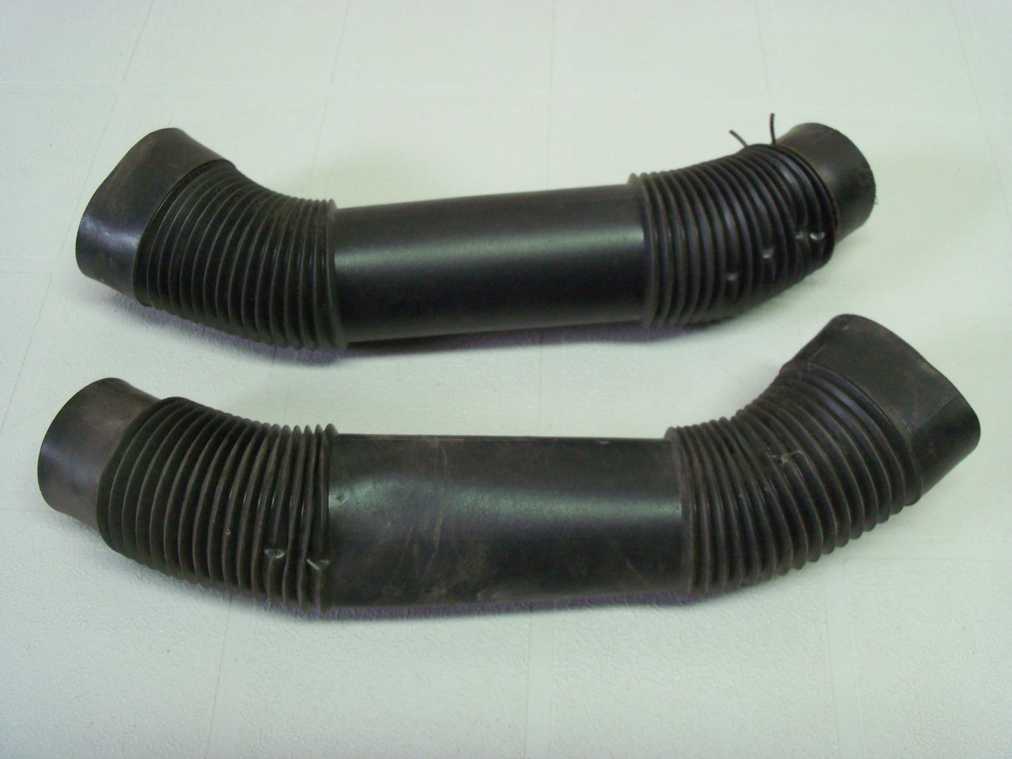
- Spring clip (need one only) for the under-dash defroster duct tubes -- these clips aren't shown in the CarPartsManual.com exploded-view drawing, but you can see one of them clearly in the photo I took of my duct tubes)
No urgency. I'm just trying to have these bits in hand before the winter is over.
John Jackson
Burlington, Ontario

-
An old friend worked in the metal-producer industry for his entire career, eventually rising to senior management. He told me that the auto industry decided to try out higher-impurity-level hot-rolled steel back in the early and mid-1970's and it backfired, big time. It seemed like all cars of that era -- not just Z's -- had issues. I remember a guy in my office who bought a brand-new full-size Chevrolet sedan, circa 1977. It had a very attractive dark green metallic paint job. A year later, a rust blotch about 1 in. in diameter appeared out of nowhere in the center of the driver's door. Pinto's, Vega's, FIAT's, TR-4's, Volvo's, Jensen's, Porsche's -- the list of rust buckets from that era is endless. Except for American Motors, that is. They ran their unibodies through an immersion tank filled with anti-corrosion primer (zinc?) before painting. Rust is triggered by localised galvanic (electrical) activity. Impurities in hot-rolled steel serve to set up exactly that kind of localized electrical cell (and poor-quality steel had a lot of those impurities built right in). If I remember my Chemistry properly, moisture (esp. with salt added) acts as the electrolyte. On exposed panels, the moisture evaporates before it has a chance to get things going. However, when you trap moisture in the seams between two panels that have been spot-welded together, you're off to the (rust) races. Even the spot-welding process seemed to aggravate the problem -- or, at least, in the cases where the steel sheet wasn't very good quality. Add a little salty seaside air (e.g. loading and unloading docks, deck-top storage on the ship) and it permeates right into those seams. If you look at photos of a typical, moderately-rusted Z after it's been lightly sand-blasted, you can see the darker corrosion areas that creep out from all of the seams. Scary. 'Rust never sleeps'. A wash with phosphoric acid ('Ospho', 'Rust Neutralizer', etc.) helps to neutralize this -- and, I believe, might even serve as a 'sacrificial' coating on top of the steel. Nowadays (after the industry finally figured out how to get paint adherence), we see one and even two-sided galvanized steel sheet used for body stampings. You rarely see rust on a modern car's body panels, except for upper-bodywork (roof, trunk, hood) where some manufacturers still used non-galvanized steel.
-
After three weekends of limited success in trying to get my DIY zinc plating set-up to deliver decent results, I think I need to bite the bullet and get my pieces done commercially. Would you mind telling me the name of the plating shop you used to get your parts done? (I'm assuming that it's located somewhere in the GTA).
Thx
John Jackson
Burlington -
Guys on the back corners look awfully relaxed, compared to the guy at the front. I wonder if this photo has been, um, 'altered'?
-
Looks like the same kind of mistake that I would have made . It's hard to put metal back on a piece after you've ground it off, isn't it?
-
There was an, "I'm leaving" message posted about a month ago by someone who might have been Blue (but he didn't come right out and say so). The poster said that he'd tired of the website's ad-tracking features, etc. -- and of the internet in general -- and was therefore checking out. It certainly sounded very Blue-like. If it was, it's our loss. He was a famously helpful contributor and seemed to be always willing to assist someone who had a problem with their Z (I think Hardway can vouch for that). He also invested what must have been an enormous number of hours in creating some of the best 'how-to' articles I've seen, covering a huge variety of jobs. I'd put him right up there with Enrique Scanlon and Carl Beck as top contributors.
-
Intake Manifold Thermostat - How do I check it and service it?
Namerow replied to Namerow's topic in Open Discussions
@ CanTechZ - I had looked at exactly the same picture in the 70 sales brochure, but the image file that I was using wasn't high enough in resolution to let me zoom in on the back of the engine. Yours is, and I agree with your conclusion. At least, to an extent. Sales brochures are usually printed a long time before a new model actually hits the showroom floor, and the vehicles used for the shoots may or may not be 100% faithful to the final production version re the odd small detail. BTW, it was fun to see in that picture how those cloth-braided ho$es came pre-frayed from the factory! @ Zed Head - Once again, I had looked at the same picture -- this time on the Z-Therapy site The caption on the picture of the 70-71 intake manifold is misleading. It says, "1970-71 non-water heated", despite the fact that the coolant pipes for manifold heating are clearly visible. Of course, what Z-Therapy are really talking about is non-water-heated carburetors, not manifolds, and in that respect they are absolutely correct: the 1970-71 carbs are not water-heated because the water-heating cavities in the manifolds -- which are there -- are not ported out to the carb bodies. I think that your take on the evolution of the whole manifold/carb-heating system is probably right. It went in steps: first, the obvious/easiest step of heating the manifolds, then the fix-up via the addition of the thermostat, then the improvement by adding carb heating. We're still left with the question of when the Manifold Thermostat was added to the design (and neither CarPartsManual.com nor the FSM's nor the TSB's seem to offer a definitive answer). Was it added on the fly at some point during 70-71 production, or did it arrive in conjunction with the carb heating feature in 72? Maybe Chickenman, c/o his Nissan Service background, has the answer... -
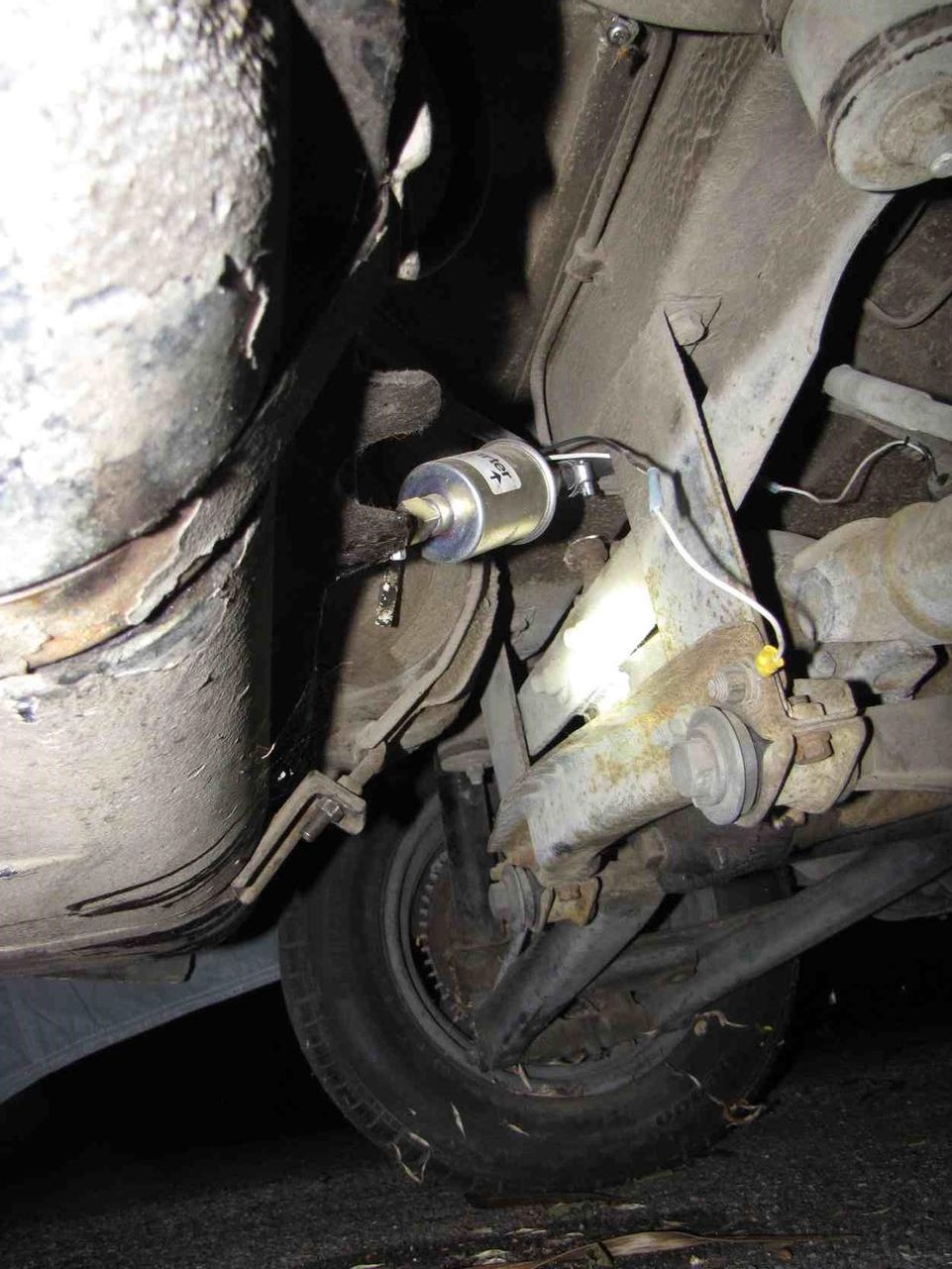
Picture of front brake assy would seem to answer the plating question asked by Careless re yellow-zinc vs. plain-zinc for the calipers.
-
240z overheating at idle in traffic lights and intersections
Namerow replied to Johnny wick's topic in Engine & Drivetrain
Carburetors have their charm, but after reading through this Nissan, 'how-to-make-it-run-sort-of-ok' document, it's easy to see why the industry embraced electronically-controlled fuel injection when it was finally ready for prime time. Of course, if there were no emissions control requirements and no CAFE rules and we all lived in San Diego, carburetors would probably still rule. -
Intake Manifold Thermostat - How do I check it and service it?
Namerow replied to Namerow's topic in Open Discussions
At this point, I believe that the key questions to be resolved are: Is there are retired cooling system engineer in the audience? Was the Manifold Thermostat actually installed on pre-72 Z's? (no speculation - we need a clear picture of the engine compartment of a guaranteed-original 70 or 71) If the Manifold Thermostat is removed to make the manifold heat circuit operate full-time, what are the coolant flow characteristics through this circuit (i.e. hi v. lo vs. no volume; front-to-rear vs. rear-to-front flow direction)... - under cold-engine conditions? - under hot-engine operating conditions? For Z's equipped with the Manifold Thermostat, does removing this thermostat (assuming that it's suspect) cause negative issues somewhere else in the cooling system? -
240z overheating at idle in traffic lights and intersections
Namerow replied to Johnny wick's topic in Engine & Drivetrain
The Manifold heat thermostat functions so that it's open when the engine is cold and closed when the engine is warmed up. If your Manifold thermostat is stuck (mine was), it's almost certainly going to be stuck in the 'open' position, which means two things: Your manifolds and carbs are probably being treated to heated coolant all the time (including when you're sitting at stop lights in 33-degree weather with a hot engine) Removing the Manifold thermostat from the circuit won't make any difference, because the thermostat was already stuck in the 'open' position. Removing the Manifold thermostat from the circuit and then blocking the circuit with a plug may not be a good solution either. There are concerns (although not confirmed) that this might create undesirable side-effects in the operation of the regular sections of the engine cooling system. I suggest that you remove the Manifold thermostat and check it to see if it is, indeed, stuck 'open'. Use the test procedure from the FSM (see my other thread for details). If this test shows that your Manifold thermostat is stuck in the 'open' position, you can probably get it working again by soaking it overnight in a jar of 'C-L-R' (chemical used for 'de-liming' electric kettles and other home appliances). You can also try carefully heating it (actually, over-heating it) with a small butane torch to see if you can get it to close. Again, see my other thread for more details. -
Intake Manifold Thermostat - How do I check it and service it?
Namerow replied to Namerow's topic in Open Discussions
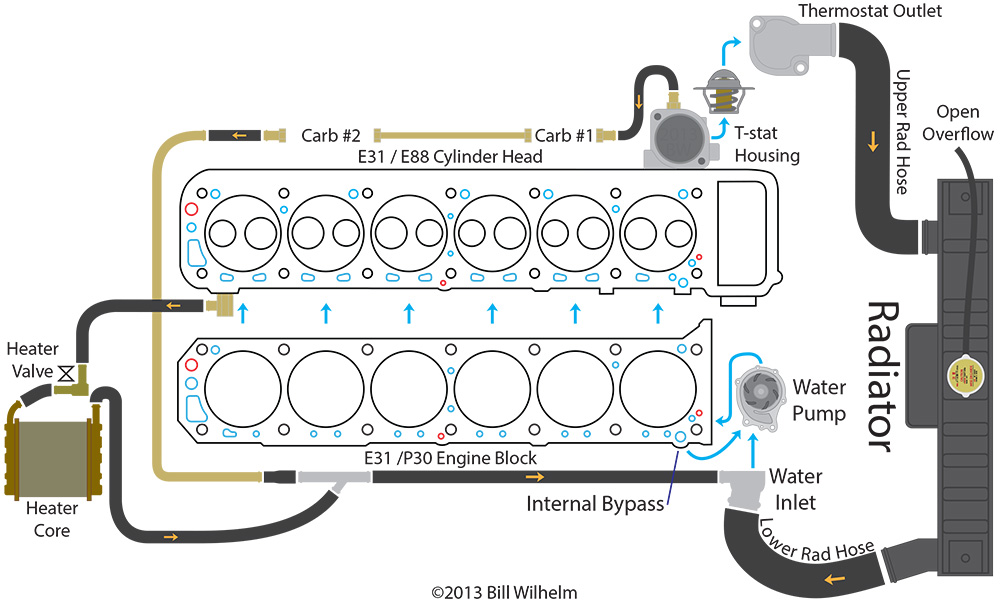
@ Zed Head and Stanley... You're right, I'm wrong. I was tricked by a my too-quick look at a different coolant diagram that appears right at the beginning of the '72 FSM's Cooling System section (see Fig. CO-1, below). While re-visiting my notes, I found a nice flow diagram (copyright credit to Bill Wilhelm) that Blue posted some time ago - also re-posted below. It provides some additional insights. All in all, though, Fig. EC-23, is certainly the definitive one when it comes to figuring out how the Manifold Heating circuit works. Specifically, until the main (rad) thermostat opens, the Manifold warming circuit is active. Coolant enters and exits the main thermostat through the base of the main thermostat's housing. Intersting that Fig. EC-23 was included in the Emission Control section rather than the Cooling or Fuel sections. Maybe the tech writers at Nissan just treated the Emission Controls section of the FSM as the dumping ground for, 'little gizmos that nobody understands'. I think the point still stands that if the Manifold Thermostat is stuck open (or removed), then the manifolds and carbs are going to be seeing some degree of heating even after the engine has reached normal operating temperature. That is, unless pressure differentials change when the main (rad) thermostat opens, so that the flow through the manifold heating circuit is reduced or stopped. The only way to tell would be try a different version of Stanley's aborted experiment by replacing the rear transfer pipe with some kind of clear tubing. @ CanTechZ... I have two rear transfer pipes (Item #26 in the parts diagram). One is known to be from my old, one-owner '72 Z. The other I recently pulled off my current '70 Z. They're identical (although the '70 has gone through several hands, so I can't guarantee that all the parts are original). I take your point, though, about how the diagram implies that the Manifold Thermostat (Item 38) is a substitute for a plain Connector (Item 20). I wonder if the early design for the manifold heating circuit tried to get by without using a thermostat (see my comments re system pressure differential, above), only to experience some kind of unforeseen problems that made it necessary to add the t-stat ($). I certainly agree with the comment that auto manufacturers resist adding anything that they can't charge premium money for... like, say, racing stripes, alloy wheels, sunroofs, chrome side trim strips, rear hatch louvres, etc. Oh, sorry -- it was the dealers who added those, wasn't it.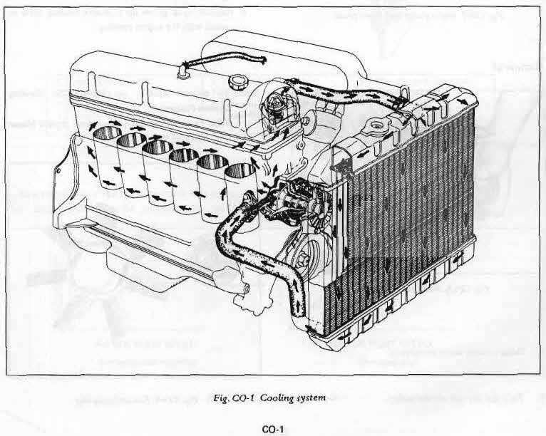
-
Intake Manifold Thermostat - How do I check it and service it?
Namerow replied to Namerow's topic in Open Discussions
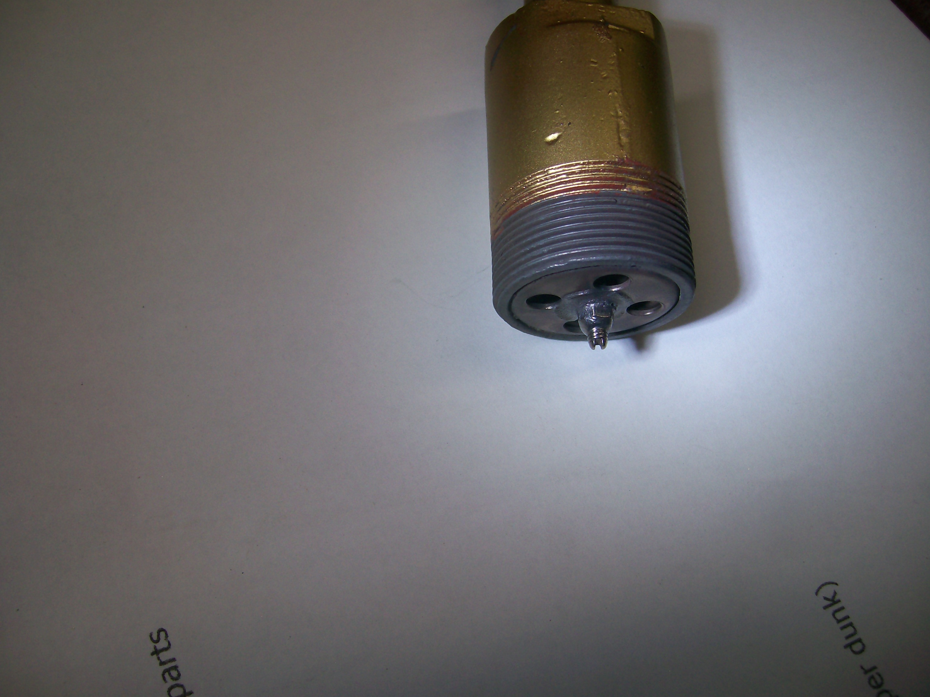
Great photo, zCars. Now we have a full understanding of what lurks inside the little cylinder. Not sure if I'd be willing to try that if I only had one thermostat at my disposal. Some further thoughts, and then I'm going to return to my plating project . 1. I did not, unfortunately, use the 'scientific method' when I was fooling around with my thermostat this morning, so I can't really say for certain that re-setting the adjustment screw was what solved the problem. Other possibilities: The heat from my butane torch might have 'excited' the wax in the actuator pellet much more than dousing it in boiling water, to the extent that expanded with enough force to break the output shaft (the one with the 'foot valve' and e-clip on the end) free of whatever crud was making it bind. All I can say is that the main housing was too hot to hold after I got done with my de-soldering exercise. Tapping on the end of that shaft with my pin punch might have also contributed to breaking it free. There may never have been a problem with my thermostat in the first place. Yesterday, I had it immersed in only about 2 cups of boiling water. That may not have been a big enough heat sink. Today, I switched to a big pot of boiling water on top of the stove. The valve was closed tight in about 30 seconds or so. Steel cap on aluminum housing. That sounds like a recipe for disaster in a cooling system component. My unit is aluminum cap / aluminum casing. To CanTechZ's point, I'm not so sure that it wasn't on the Series 1. The wording in the 72 FSM is a little cryptic, in my opinion. Also, the Parts Manual doesn't show any start date for this part -- just an end date. That implies that the manifold thermostat was part of the design from the get-go. Given that the thermostat operates in 'closed' condition under normal engine operating temps, its absence in this secondary coolant path would lead to manifold heating under hot engine temps. That seems wrong. The no-thermostat solution to this would be to block off the circuit -- which would beg the question of why the circuit is there in the first place. Do you see it otherwise? Maybe Carl Beck or 27th can comment. 2. It occurs to me that the thermostat's adjustment screw may not be so much for ensuring that the valve closes fully, but rather, how much time it takes for the valve to close. Of course, it may affect both. zCars' new photo shows about 3/16" of exposed thread on the stem of the adjustment screw. Mine started off with about 1/8" of exposed thread, so comparable. My car was made for the USA/Canada market and I suspect zCar's was too. More exposed thread on the adjustment screw implies longer travel (valve starts off further away from its seat), thus longer time before the valve meets the seat. Makes sense for moderate-to-cold climates. I wonder if Nissan dealerships in tropical climates got a field service bulletin suggesting that they trim the valve for less travel/faster close? (jalex, are you listening?). If so, I've now got mine adjusted for 'tropical' conditions. Maybe I need to try the boiling water test again, with the screw set back to where it was in the first place! ... (pause) Yep. Confirmed. I went back to the shop and backed the screw out about an 1/8" and then put the torch on it like previously to get things 'warm'. Valve closes nicely. Conclusion: It now looks like the the C-L-R dip followed by the combination of thermal shock (torch) and impact (hammer and punch) is what did the trick. Turning the adjustment screw in and out might have helped, but I can't say for sure. I'm leaving my adjustment screw back at the 'factory' setting. I'll put a single wrap of teflon pipe-thread tape on the housing/cap threads, tighten things down, and then declare it, 'Job done'. Small part. Long story! -
Intake Manifold Thermostat - How do I check it and service it?
Namerow replied to Namerow's topic in Open Discussions
Re Zup's last post: Thanks for the link to the HybridZ posting. The possibility of water pump cavitation might support my fears that this silly little valve is more important than it may seem at first glance. Not sure if the cavitation issue has ever been verified in actual practice, but it seems plausible. Anyway, I hope that my discoveries over the last 24 hours will provide a new option for Z owners who don't have their valve installed but still have it tucked away in their spares bin. Maybe zCars will have his two about-to-be-restored manifold thermostats up for sale on eBay soon! -
Intake Manifold Thermostat - How do I check it and service it?
Namerow replied to Namerow's topic in Open Discussions
Hah! Gentlemen, we have closure! My manifold heat thermostat now performs perfectly. Here's what I did (after the four-hour soak in C-L-R, of course): The little adjustment screw and locknut that appeared to be seized together forever were, in fact, soldered together. If you look closely at my #3 photo above, you'll see what appears to be a shiny-silver, crowned nut. It was only when I put my micro-torch to it and saw things starting to melt that I realized the truth. I broke the nut free from the (brass/copper) top plate first using a 4mm box-end wrench and then backed it off about one full turn. Then I tackled breaking the adjustment screw free from the lock nut. I rigged things up in my bench wise so that both thermostat housing and box-end wrench were anchored and could turn and so that the wrench couldn't lift off the nut when I tried to turn the screw (sorry, no pix -- not enough hands). That left one hand free for the torch and the other for the screwdriver. You need to find a screwdriver whose blade fits tightly in the slot on the end of the adjustment screw. Otherwise, you'll round out the slot and it'll be 'game over'. Heat with the torch until the solder melts enough for the screw to turn within the nut. Then turn the screw in until you use up the available adjustment. Now, put the torch way and turn the re-locked screw-and-nut with the box-end wrench until the nut snugs up against the housing's top plate. With a small-dia. pin punch, push Item #6 ('Supporting Plate') down against its spring a few times, just to make sure it's moving freely. Now test in a big pot of boiling water, using the test method mapped out in the FSM (see Zed Head's posting, above). Do NOT accidentally suck boiling water up the hose into your mouth! Assuming that your 'hot' test is successful, now dunk the assembly in cold water and verify that the valve re-opens. Re-solder the screw/locknut pait to each other and to the housing's top plate. Have a beer to celebrate your now-ready-for-action, 40-year-old, NLA-anywhere, 'Manifold Heating Thermostat / Switch' ! p.s. I am now taking orders in my new retirement business of fixing Nissan manifold heat control valves. May I take your order, please? WARNING: This is a fiddly little job. If you lack patience or have had a couple of beers to get prepared, you will likely end up with: 1) a broken valve, 2) burned fingers, 3) scald marks, 4) all of these. Also: Don't forget to do the boiling water test before you start. No point wasting time on a job that doesn't need doing. -
Intake Manifold Thermostat - How do I check it and service it?
Namerow replied to Namerow's topic in Open Discussions
More... OK, I think I've figured out how the adjuster works. I now see that there are two springs inside the assembly. The inner one (small diameter) serves the obvious function of resisting the valve shaft's motion relative to the pellet. The outer spring (large diameter) sits just inside the bore of the housing and supports Item 6 ('Supporting Case'). The pellet and attached shaft with valve are mounted to Item 6 (hence the name, Supporting Case). When the adjusting screw is turned, it moves Item 6 down towards the valve seat, thereby reducing the pellet and valve closer to the valve seat. Looking down into the main housing through the 'outlet' port, I can now make out the actual valve. It looks like it's sitting about 3/16" - 1/4" off the seat. That seems like a long way, so maybe turning in the adjuster screw would help achieve full seating of the valve (I've got about 1/8" of adjuster thread length available). Time to get out the micro-torch and my miniature socket wrench set! p.s. re Zup's photos and notes, that '73 valve looks like it's identical to the '72 unit that I've got. The PO just unscrewed the top cap and inserted a 90-degree pipe elbow between the two parts. The thread used on the manifold thermostat's main housing and cap is not a pipe thread (instead, it looks like a fine thread of ~ 19mm dia), so who knows how that pipe fitting was attached (hard to believe that the PO invested in a 19mm tap-and-die set). I bet there's a lot of pipe-sealing compound in there! -
Intake Manifold Thermostat - How do I check it and service it?
Namerow replied to Namerow's topic in Open Discussions
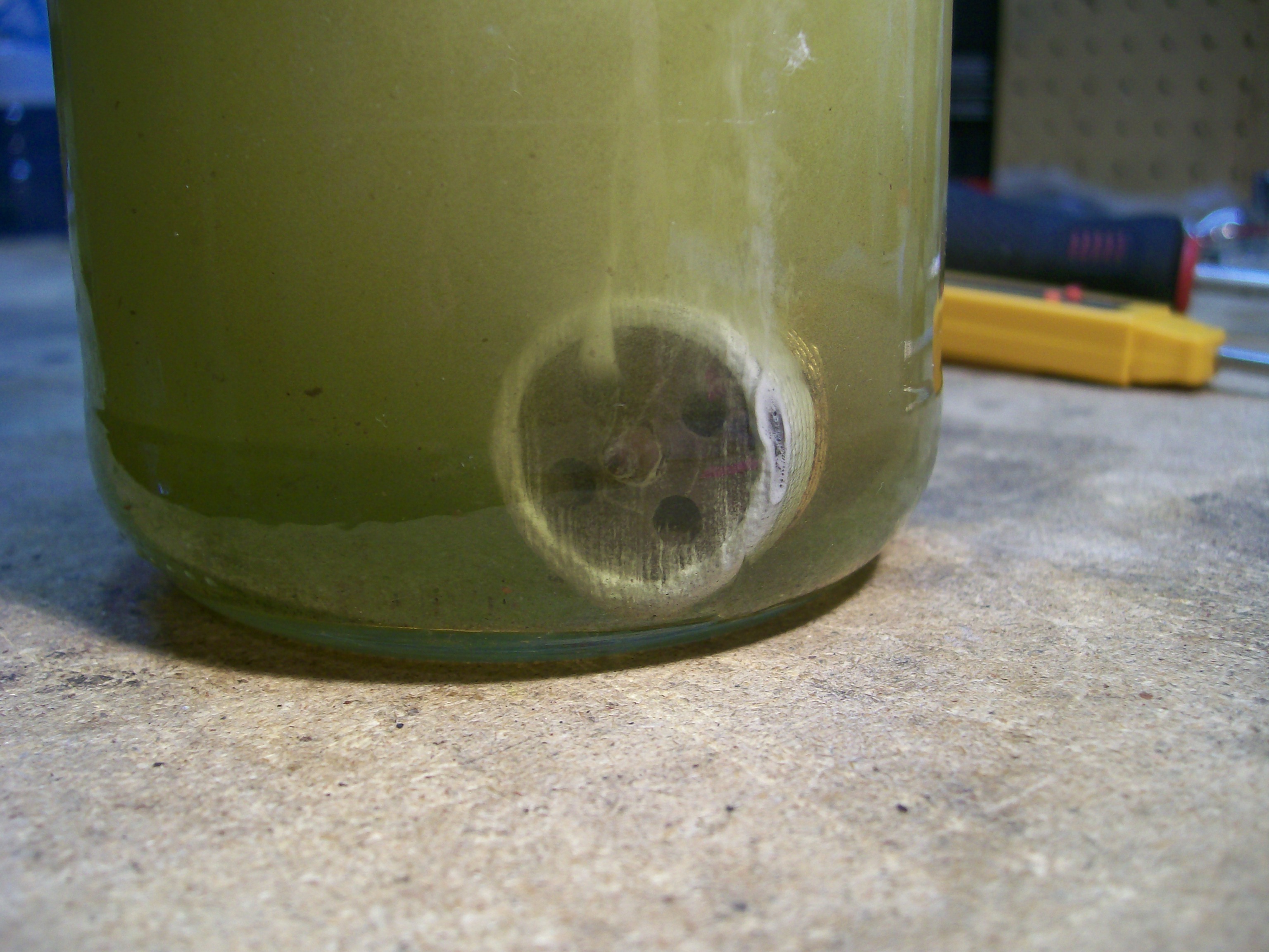
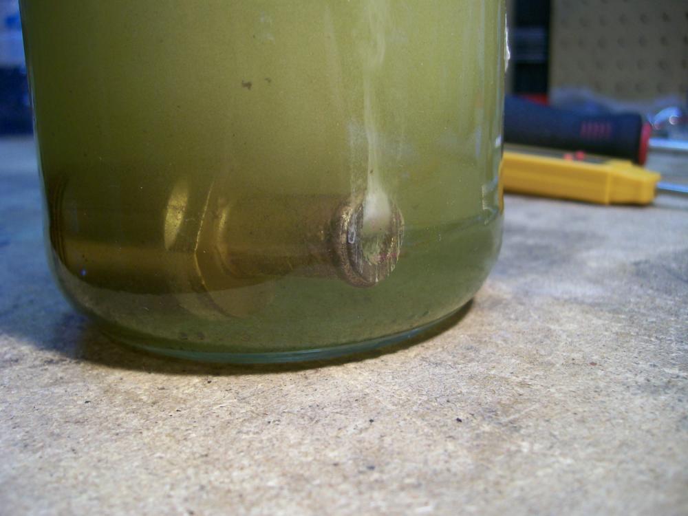
Update - Sunday AM Well, I'm afraid that the C-L-R 'de-liming' didn't work . I soaked the T-stat main assembly for about 4 hours. The bubbling action was strong and constant... so much so that it began to occur to me that the stuff might be dissolving something other than just mineral deposits (like brass, maybe). Anyway, I pulled the valve out of the C-L-R and repeated the 'blow test' (per the FSM-recommended procedure). Used boiling water fresh from the kettle (showed as 195 degrees F, although immersing the valve probably dropped it to 180 - 185). I sucked up the water into the valve -- to ensure that the pellet was actually seeing the hot water -- and then waited for over three minutes to see if the valve would close. No joy. After this, I removed the hose that I'd connected to the valve and then clamped the valve housing in my bench vise so that the outlet port (i.e. hose end) was facing up. With my inspection light, I could clearly see the tip of the tip of the pellet shaft, c/w the little E-clip on the end. Using a small pin punch, I tried lightly tapping on the end of the shaft to see if it would show signs of movement. Nothing. Then I tried pushing down as hard as I could on the pin punch to see if I could move the shaft back against the internal spring. Still nothing. So I'm at an impasse here. Non-functioning part that's locked in the undesirable position (i.e. always open, meaning that hot coolant will always be flowing through the intake manifold passages, even when the engine is up to temperature). Don't know if it's seized, out of adjustment, dead, or all three. As you can see from the third picture, the little lock nut and adjuster stem are tiny and both appear to be made of brass (i.e. fragile). They also look like they're firmly attached to one another, so I'm reluctant to put a wrench on the nut to see if it will turn. I'm even more reluctant to put a screwdriver in that itty-bitty slot to see if the 'adjuster' will turn. Also, I'm not even sure how the adjustment works (I think that turning the screw may just move the whole pellet/shaft/valve downwards towards the valve seat). I suppose that I could heat the assembly carefully with a butane micro-torch (that would certainly get the actuator pellet's attention!), although I'm worried that I might weaken or destroy the valve (presumably made of neoprene) in the process. (sigh) It's an interesting state of affairs. Putting the valve on the engine in it's current state will be no better than just leaving it off -- and either of these approaches is non-desirable, because -- as note previously -- the result is hot coolant flowing through the intake manifold all the time. If I simply block off the valve or its connector hose, it would seem to be a recipe for crud building up inside this part of the coolant circuit (and maybe even trapped air that could get into the main circuit and cause problems somewhere else). I wonder if there's another car of similar vintage that used an inline coolant control valve like this? If so, there might be an alternative solution. If I knew that there was another part out there that I could conveniently purchase, I'd pry my Nissan valve apart to see exactly where the problem is. Suggestions, anyone?

-
Chris: PM sent
-
Intake Manifold Thermostat - How do I check it and service it?
Namerow replied to Namerow's topic in Open Discussions
Very cool. Thanks, guys. An update from my end: The labelling for Fig. EC-20 is, indeed, reversed re Items 7 & 8. The 'case cover' is simply threaded onto the main casing, so it's easy to get off (big hex-nut fitting). After the cover is off, though, there's a brass cap (from which a central shaft with the adjusting nut protrudes) that looks like it's a press-fit into the main casing... so I'm probably never going to get to inspect the innards without destroying something. I've got my thermostat soaking in CLR now. There was a lot of 'action' right off the bat, so my suspicion about mineral build-up might be correct. We'll have to wait to see, though, whether it frees up the workings. Interesting that the designers decided to add an adjustment facility for such a simple device. That may explain, too, why there's a threaded cover rather than just making the device completely sealed. Maybe they knew something we don't ! Don't know if anyone else spotted this, but the intended flow direction for the coolant is the reverse of what I would have expected. According to the FSM diagram (unless this is another labeling error), when the T-valve is open, the coolant is flowing out of the rear bypass tube, through the T-valve, then into the manifolds, and finally exiting into the main thermostat casing at the front of the engine. I always thought the flow direction was the opposite (i.e. from front to back, and then around the rear of the engine into the Y-fitting). I guess I'll have to go back and look at those coolant flow diagrams that someone came up with in the midst of that long debate over whether or not it's safe to bypass the cabin heat coolant circuit. I'll report back tomorrow on whether or not the CLR soak worked. -
I have one (1) 'Intake Manifold Thermostat' in my parts bin (PN 14100-E8850). As you probably know, this valve is NLA from Nissan and appears to be NLA from all the Z specialty suppliers too. Its job is to control the flow of coolant through the intake manifold heating cavities (which also duct out to the carb bodies for 1972-73 models). I expect that it's arranged to work the opposite of the regular coolant thermostat: i.e. it operates open when cold, then closes off flow once the coolant heats up). According to the Parts Manual, they were fitted to the Z engines right up until July 1973. I want to fit my parts bin unit to my '70 (which arrived with the manifold thermostat missing), but only if it's working properly. I just tried a dunk test in boiling water and it wouldn't close, so I assume that it's jammed in the neutral/open position because of the usual chalky crud that can build up in a poorly-maintained cooling system (my unit hasn't been installed in an operating vehicle since 1980, so it hasn't been 'exercised' for a l-o-o-n-g time) Does anyone have any experience with fixing these little thermostatic valves? I can't find any mention of it in either the Z FSM or the L24 Engine FSM -- not even a note on a diagram to indicate that it even exists. Q1: I'm thinking of soaking it in CLR, on the assumption that it's mineral deposits from tap water that are causing the problem. Has anyone tried this? Q2: What's the correct temp. at which it should start to close? And how long should it take for it to cycle from fully open to fully closed? Q3: Do I have the operating logic correct? (i.e. normally open, then closed when hot). Is it designed to fully close, or just partially close? Q4: There's a tiny phillips-head screw with an equally tiny lock nut on the tip of the internal centre shaft. Has anyone tried to take one apart to assist in cleaning up the moving parts? Q5: Does anyone know of a source for these (either NOS or used)? Any guidance welcomed.
-
Hi Chris: Just thinking out loud here... Eyeballing it, I see fab based on welding it up from five separate pieces: left, centre, right, full-width apron, and the little reinforcement gusset between the apron and the 'left' piece. Creating the curved flange on the 'left' piece looks like the biggest challenge, but one of those Eastwood shrinker/stretcher tools would get it done. With cutting, forming and welding, it looks like maybe 5 - 10 hours of work. Let's be optimistic and call it 5 hours and value your time at, say, US$50/hr (includes shop overhead cost), so that's $250. Add in materials and consumables at another $50 and you're now sitting at $300 per piece. Add a profit margin, too, so it looks like an 'advertised price' of $350 would be about right. Forget about stamping this from one piece -- there are some pretty big draws involved here. At this point in time re access to large-scale 3D printing equipment, I'd say forget about that, too. Nevertheless, I'll check with my university contacts later this month to get a second opinion. It's a fast-developing technology and you never know what lies around the corner.