Namerow
-
Posts
1,483 -
Joined
-
Last visited
-
Days Won
23
Content Type
Profiles
Knowledge Base
Zcar Wiki
Forums
Gallery
Events
Downloads
Store
Blogs
Collections
Classifieds
Everything posted by Namerow
-
I did this swap for my '70 Z last year, using the blower motor and impeller from a Civic. While bench-testing the unit with the newly-installed Honda parts, I discovered that the output performance (CFM) of the Honda impeller is extremely sensitive to direction of rotation. Perhaps you have your motor wired so that it's running the impeller in the low-output direction? FWIW, I tried the same test with the old Nissan motor and impeller and found that the OE set-up provided about the same CFM output (modest) in either direction! This suggests to me that the Z's impeller is poorly designed and performs more like a paddle wheel than a centrifugal fan.
-
You could perhaps try an application of regular-duty epoxy to inside surfaces of both bushing shell halves before re-assembling with the bushing in place. If you smear the spherical outer surface of the bushing with grease or oil before re-assembling the retaining shells, it should break free of the epoxy bond after the epoxy has set up. You'll end up with an epoxy liner inside the bushing shells. Warning: I haven't tried this, but I think it would work. If it doesn't turn out satisfactory, you can probably remove the epoxy from the bushing shells with a Dremel rotary tool and then try something else.
-
This is an old thread, but it came in handy when I started taking my wiper linkage apart yesterday evening. It wasn't immediately obvious to me how to remove the circlips on the intermediate and end shafts. None of my circlip removal tools would work. Here's what I came up with, after a bit of experimentation. Hope it saves someone else some head-scratching when they get to this point: The circlip that holds each pivot shaft inside its alloy casing is made from hardened steel. It has no 'ears' to assist with removal. To remove without damaging clip or retaining groove: 1) Clamp the alloy casing in a vise (use jaw pads) 2) Find two medium-size flat blade screwdrivers (tips should be 3/16' - 1/4" in width) 3) Insert the tip of screwdriver #1 between the circlip ends. Hold it steady against one of the circlip ends so as to keep the clip from rotating as you... 4) Insert the tip of screwdriver #2 next to that of screwdriver #1 and then push outward against the other circlip end. Expand the clip and lift the end out of the retaining groove. 5) Now relocate the tip of screwdriver #2 to sit in the shaft's retaining groove under the lifted-out circlip end. 6) Using screwdriver #1, push against the circlip's still-seated end to rotate the clip so that it progressively rides up over the tip of screwdriver #1 and out of the retaining groove. You should be able to re-use this clip. The circlip that retains each of the intermediate pivot shafts in its eyeball joint does have 'ears'.. but they have no holes and are therefore not of much use in the removal process. What won't be immediately obvious, however, is that these circlips are made out of soft, deformable metal. You can use the same removal technique as that described above for the circlips on the alloy-housing shafts. However, these clips will actually stay deformed as you expand them to lift an end out of the retaining groove. It doesn't seem like it would be a good idea to try to re-use these soft clips -- they'll probably be ready to fracture or pop out of place at some point shortly after you've put everything back inside the cowling. For reference when sourcing a replacement, the diameter of the retaining groove is 6.9mm / 0.27". The OE felt washers measure 21mm OD x 17mm ID x ~ 3.5mm thick. There is one washer fitted to each of the (four) compliant pivot points in the linkage assembly. Hard to say whether they were grease-packed or oil-soaked when new. Whatever was used, I think it was done to prolong the life of the washer rather than to serve as a source of backup lubricant for the mechanical part of the pivot.
-
If you intend to use a wire wheel for cleaning up the area, pre-solder, I would suggest that a brass wire wheel is the safe choice (less potential for sparks).
-
Related question: Does anyone sell these new?
-
 Metalmonkey47 makes a good point. I found that the heater valve ('water ****' in Datsun-ese) in my Z was frozen solid at the main pivot point of its linkage. This apparently frustrated the previous owner to the point where he/she forced the 'TEMP' control lever so hard that it bent the control cable. I simply soaked the heater valve in water-based parts cleaner for a week, then cleaned and lubricated the linkage and put a drop of Armorall on the valve's push-pull shaft where it pokes out of the casing through a small, neoprene, disc-style gasket. Now it works and seals just fine. That said, most of the foam gaskets in my car's heater box and blower housing had disintegrated from age. The control lever assy also needed repairs, along with cleaning and lubricating. Although the system might have worked after the heater valve and control cable were fixed (the heater core was fine), I'm not sure that it would have worked particularly well. In the end, it all depends on what final result will satisfy you. It may very well be worth pulling the heater valve first and either servicing it or putting in a new one. If you go this route, though, be prepared for a hour or two of awkward work. IIRC, you will need a 1/4"-drive socket set and a stubby Phillips screwdriver (and maybe an offset Phillips screwdriver too). One or two of the Phillips screws may be reluctant to loosen, so its worth spraying all the fasteners with penetrating oil a week or so before you get started.
 -
I went thru the steps to pull the heater/blower assy in my '70 Z last year. Although I was able to remove them successfully w/o pulling the dash, I eventually decided to do that too... so I now have experience with both strategies and will offer these comments: 1. I you decide not to pull the dash, you'll need to remove both the glovebox liner and the HVAC controls faceplate in order to gain the access you'll need to get the heater and blower out. Many steps along the way require a lot of contortion and will favor agility, small hands, good lighting, and a lot of patience. You'll need to detach the heater control cables from the heater/blower assy. The cable clamp on the water valve could be problematic if there's been long-term leakage. The water valve may be seized, leaking, or both. 2. Removal of the glovebox liner is not an intuitive process, nor do there seem to be any good step-by-step instructions or photos available to guide you (incl. the FSM). It will not come out from the back (there's stuff in the way). It will only come out from the front. IIRC, I had to bow in the top edge first, and then bow in both sides. Eventually, if you bow in all 4 edges sufficiently, they corners will clear the opening in the dash by just enough to pull the liner out. If you're lucky, it won't tear or crumble in the process and might even be reusable. 3. Once you've got everything freed up, the heater box assy can be pulled out from the passenger side (best to pull the blower assy first, as a separate unit -- caution: it may be stuck where it mates up against the cowl panel). Be sure you put down some newspaper on the pssgr-side floorboard, because you're going to spill coolant when you detach the heater hoses and when you pull out the heater box. 4. When all is said and done, you may wish that you'd just pulled the dash first. It might just end up taking the same amount of time overall and it sure makes getting to the heater and blower a lot easier (for both removal and reinstallation). Also might make removal of the glovebox liner unnecessary (not sure about this -- maybe someone else can comment). Pulling the dash will also give you an opportunity to inspect and clean some key wiring harness connectors and replace all of the gauge lights (v. difficult to do with the dash in place, and nearly impossible for speedo and tach if your dash has a cap installed). Let us know what you decide to do.
-
Ferrari 250 replica based on a 260Z wants $ 100,000
Namerow replied to bartsscooterservice's topic in Internet Finds
Is this not simply the glue-on/bolt-on fibreglass body panel kit that someone used to sell years ago? I think it was called 'Alpha GTO'? This car looks very much like that kit (i.e good, but just not quite right, so a little bit cartoon-ish). -
p.s. The big crank bolt uses regular threads, so you turn CCW to remove.
-
I recently went through this process (crank bolt removal, followed by pulley removal) with my '72. I considered all of the alternatives and decided to start with my electric impact wrench (1/2" drive, nothing special). Radiator was out of the car, so I had good access to the crank bolt. The cylinder head was off the engine, so no hope of relying on compression to resist torque applied to the bolt. I just put the car in gear and crossed my fingers. The bolt gave way very easily. Despite the high torque used to install this bolt, its threads live in a very clean environment and are unlikely to have rusted (even though the bolt head will probably be very rusty). Mine had clesan threads from top to bottom. I used a 26mm, 6-point, non-impact type socket (impact type socket's walls may be too thick to fit into the pulley recess). I expect that using a breaker bar instead of an impact wrench will probably require a lot more effort towards keeping the crank from rotating. The 'high-torque chatter' generated by the impact wrench seems to be the key. The next 'non-challenge' turned out to be getting the pulley off the crank. Here, too, I was afraid that the pulley would be rust-seized onto the crank snout. Instead, it actually offered very little resistance and slid off quite smoothly. I used a steering wheel puller, with long-ish bolts (M8, IIRC) threaded into the two threaded holes in the pulley hub. Had to use a tap to clean out the pulley hole threads first. The engine I was working on was high-mileage and I doubt whether the pulley had ever been removed previously. Rossiz posted a nice review of his pulley/timing cover removal process about a month ago, with lots of pictures. Your results may vary, of course, but I think you may find it's not so problematic as you're expecting.
-
Removing glue from vinyl trim and interior surfaces - What works best?
Namerow replied to Namerow's topic in Open Discussions
I went 'chemical shopping' on the way home from work yesterday, so now have a full assortment of stuff to try out this weekend. @djwarner: The tin of MEK I spotted at in the store specifically mentioned on the label that it was good for contact cement removal. Out of curiosity, why do you recommend against? -
Removing glue from vinyl trim and interior surfaces - What works best?
Namerow replied to Namerow's topic in Open Discussions
Thanks, everyone. Lots of options to investigate. I think I'll try them all, and will report back later on my results. p.s. the paint in question here is the original factory paint, as applied on the interior panels (rear wheel housings, etc). -
I've stripped the soft vinyl trim out my 70 Z's interior and I'm now attempting to remove the old contact cement from the interior (painted metal) surfaces. Naptha is proving to be only sort of ok. It's effective only in the lightly-coated areas. It doesn't seem to do much more than encourage lightly-gripping glue remnants to roll up into 'balls' (after much scrubbing with a naptha-soaked cloth). Household glue remover ('Goof Off') seems to be better at actually dissolving the glue, but the contact area of the cloth quickly gets loaded up with dissolved glue and then it feels like I'm just rubbing dissolved glue into the stuck-on glue. Anybody got any secret tips for getting this stuff off? (my arm's getting tired)
-
One key point hasn't been mentioned yet. Going the dash cap route means that you won't have to pull the dash out of the car (not a trivial task -- especially if you've never done this before) and won't have to re-install the new/refurbished dash afterwards (see previous comment). The dash cap will also: 1) save you a lot of $$$; 2) give you a durable surface with an OE-look texture; 3. take away the risk of new cracks appearing in a DIY refurbished dash. That said, you'll find lots of comments on this site about caps often needing some massaging (heat gun) and shaving (of the lips that fit inside one or maybe two of the gauge or air vent recesses) in order to fit properly. You will also need to use the right adhesive (and in only the right places) to create a good-looking installation that won't warp or bow/cave afterwards. One member here (name?) has posted a detailed instruction set for installing a cap. His results were very impressive and convinced me that that was the way to go. In my case (240Z), I already had a cap so the issue of whether or not to buy one was not a concern. However, when I attempted a trial fit, I found that my dash had 'grown' in width (due to the 3 cracks, I guess) to the point where the cap simply wouldn't fit. I ended up having to pull the dash and refinish it -- a job that took several weekends to complete. Although I'm happy with the end result, it wasn't easy to get right and I still think the cap is the better way to go (if it fits). At worst, you'll only be out the cost of the cap. The best, cost-is-no-issue solution is to pull the dash and send it to Just Dashes (California) for a professional repair and re-cover. They repair the cracks, re-contour the undersurface, and then apply a new top skin with the correct texture. They use a vacuum-and-thermoforming process to pull the new top skin around all of the contours and down into the gauge recesses. With the costs of crating and two-way shipping included, this approach is probably going to cost you $1,500 - $2,000.
-
Latch rubber bits are being offered as a 5-pce set (per side) by Datsun 240z rubber grommets & parts $15.00 per set. Website says, 'Only 4 left'.
-
Where to find correct 7.8mm / 5/16" spade terminals?
Namerow replied to Hardway's topic in Electrical
You'll find four more of these 5/16" (8mm) spade connectors in the dash-to-front harness connector bundle, over under the RHS of your IP. In my May '70 Z (dash is out of the car at the moment), a couple of these also show signs of the same heat/corrosion issue. Working on the assumption that the (electrical) chain is only as strong as its weakest link, you may want to service these connectors too. FWIW, I also found that the copper wire was corroded in the terminal crimp area. There's wasn't enough wire slack to make me feel comfortable about chopping off a 1/4" to get to some shiny wire, so I polished the corrosion off with a Dremel (using the little wire wheel attachment) before crimping on the new connector. -
When an ex-pat Brit car-buddy saw my freshly-restored Z heater box, he said that it looked just like the 'Smiths' heater boxes that he used to see when he worked in the auto trade in Britain back in the late 60's/early 70's. I can't vouch for whether it's a straight-on copy, but it's always worth remembering that Nissan's corporate president in the formative post-war period was something of an anglophile (responsible, in part, for the model names like Cedric, Fairlady, Bluebird, etc.) and the company had a working relationship with BMC/Austin in the 1950's that in many ways led to the 1600 and 2000 Roadsters (and, later, the Fairlady Z, aka 240Z).
-
I learned that working with music wire has 'special challenges'.
-
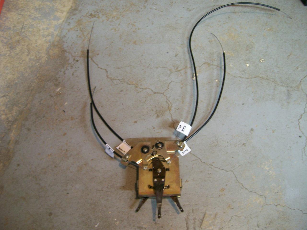
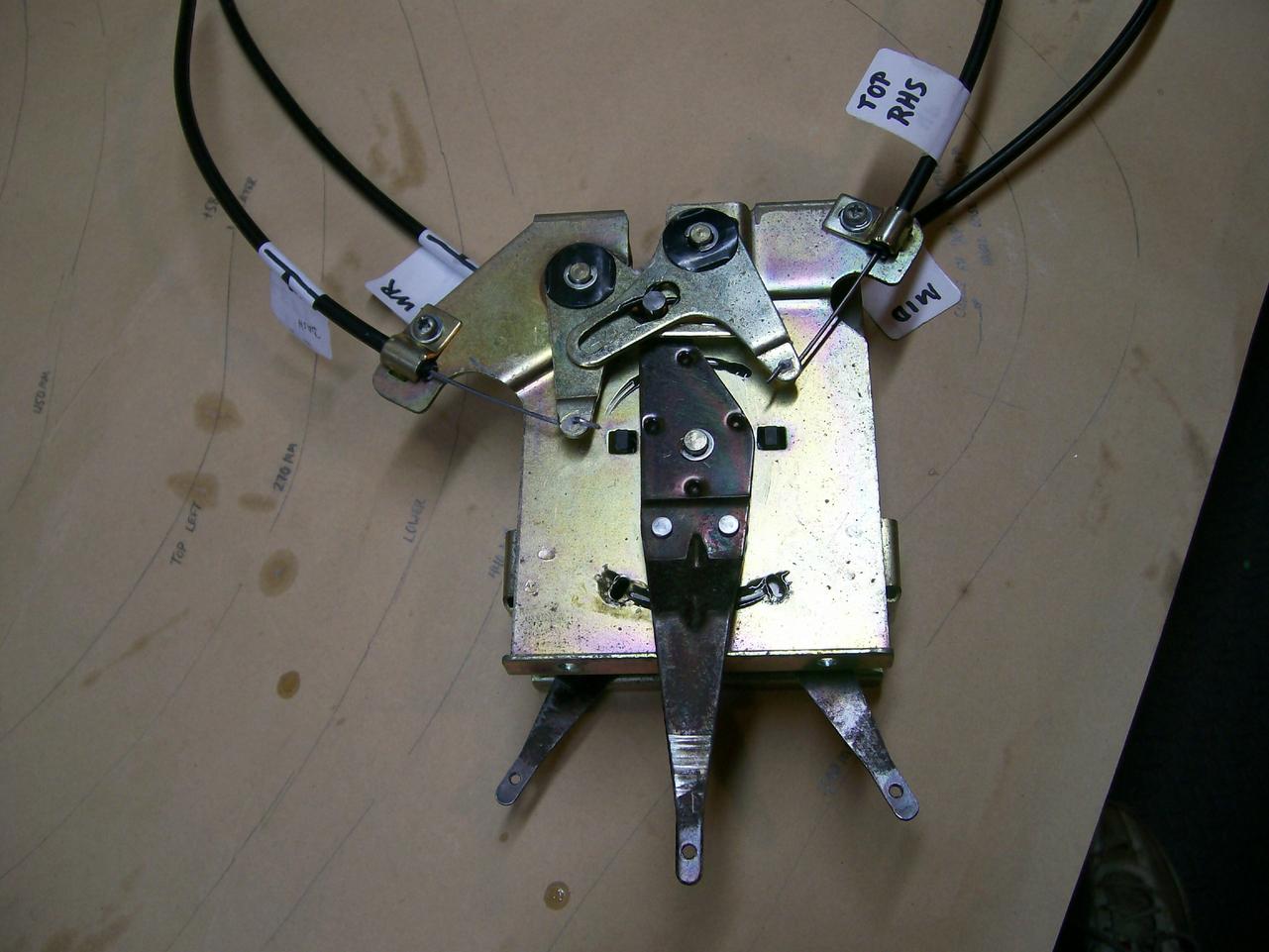
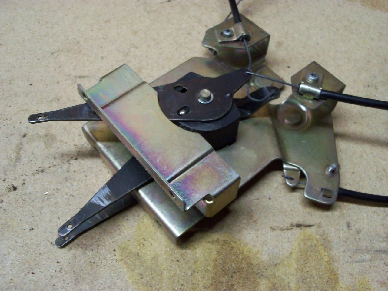
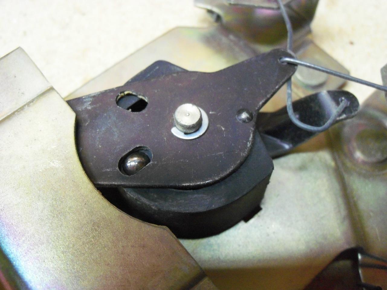
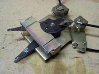
You're right. Those cables aren't OE. I re-built the cable/lever system for my '70 Z last winter, having had a very similar issue with a bent-up control cable (along with a few other problems). I also had parts on hand from a '72. Here's what I learned. The control cables for the '70 are 1.0mm diameter. The cable ends (at the Heater Box) are straight. Cable sheaths are smooth black flexy-plastic, ~ 4.7mm OD and ~ 1.0mm wall thickness. The control cables for the '72 are 1.3mm diameter. The cable ends (at the Heater Box) are looped. Cable sheaths are the same smooth black flexy-plastic, ~ 4.8mm OD and ~ 1.0mm wall thickness. For the '70, the cable sheaths were in good shape, so I re-used them. For the cables, I bought a coil of 1.0mm tempered steel wire ('music wire') and put the 'dog-leg' bend in (for the lever end) by bending in my bench vise. I had to take the curl out the wire (comes in a tight coil) by pulling the cable back and forth over a length of round bar stock that I clamped in the vise. Hope this helps. I've posted a few pictures of the '70 lever/cable assembly to illustrate.


-
My dash had three, full-span cracks and that was what made me decide to do the repair. However, when I had the dash out and sitting on my workbench under good lighting, I found a few tiny hairline cracks (~ 1/16" long) along the forward (windshield) edge. My guess is that these little cracks are the way that the big cracks get started. All I did was grind out the vinyl top surface locally so that the ends of each little crack got round edges. What I would end up with in each case was a cut in the vinyl that was the width of the tip of my Dremel bit ( ~ 1/8") and -- in length -- a little bit longer than the original hairline crack. The ball-shape of the Dremel bit automatically gave me the rounding that I wanted at each end of the crack. If you've got a long hairline crack (I've never seen this -- they usually open up, starting from the windshield and getting wider as they track towards the gauge openings), you still need to: 1) 'V' the edges of the vinyl all along the length of the crack (so that you filler coat has something to bond to), and; 2) round off the end of the crack, to stop it from growing any further. You should probably try to fiberglass along the underside of the dash foam too (that is, if you can access the crack area from underneath), because a long hairline crack is almost certainly going to grow as the old foam shrinks and pulls back (and Bumper-Bite filler on the top isn't going to stop this from happening).
-
I've just finished my dash project. Will post pix and notes later, when time allows. I tried a lot of different bits in my Dremel when working on the vinyl overlay (which is ~ 1/16" thick). It's very a tricky process. Too aggressive with bit choice/speed results in melting rather than abrading, and creates a mess. The goal is to feather-edge the vinyl so that the top-coat filler (I used SEM Bumper-Bite) has a good edge to bond onto. In the end, I found that an engraving-type bit (all-metal, ball-tip -- not the textured tip -- the one I had good results with looks like it's fluted, like a drill bit) with medium-low rpm worked best. My attempts with various rotary sanding discs were unsuccessful (too easy to overshoot the vinyl and accidentally create unwanted deep gouges into the old foam underlay). This job requires a lot of patience to do right. I used a cable-type extension drive, hooked up to my Dremel tool, in order to get the bit at the right cutting angle. Remember to wear safety glasses (a small chip of vinyl cutting lodged in the eye is not a happy experience - don't ask me how I know this). Be sure that you cut back the vinyl and oem foam far enough away on each side of the crack to get past the curled-up area. Otherwise, you'll end up with a big problem when you start sanding. Avoid cutting too deep into the oem foam during this cut-back process, Otherwise, you'll end up having to use too deep a layer of Bumper-Bite (which, by the way, isn't really all that flexible). Aim for a depth of Bumper-Bite fill that's no more than 3/16". Important FYI - Even though the textured bedliner paint looks like it will mask small mistakes in your sanding/contouring job, you may as well know right now that it doesn't. Be sure to put a full primer coat over the sanded areas of your dash before you even think about reaching for the bedliner spray can. Then take a long, hard look at your work under natural sunlight before you proceed to the bedliner spray (shop lighting won't tell you the whole story). I found that sanding the Bumper-Bite to get true contours over the arches of the gauge clusters was r-e-a-l-l-y difficult to get right (you'll be working with a combination of concave, convex and flat surfaces -- the convex ones being the most difficult to get right). Recommend you get a set of hard-foam sanding blocks from Eastwood for this job. There's one in this set that has an onion-type cross-section that works really well for the concave and flat surfaces of this job. However, none of these blocks is suitable for the convex contours of the gauge bezel peaks. I recommend you find a piece of properly contoured thick rubber for this part of the job (go to the plumbing section of your hardware store and look for a large-diameter rubber pipe-joint, and then cut a small section out as your sanding pad).
-
Nice write-up and pix. Thanks for taking the time (during and after). It's good to see that the cautions about 'jack-up-the-engine-and-remove-the-oil-pickup' were unnecessary. I'm curious to hear more details about two components of the work that you say much about (and which have earned commentary in write-ups by others): 1. What tool(s) and procedures did you use to loosen harmonic balancer securing bolt? Degree-of-difficulty rating? Did you just put the car in gear rely on wheel chocks to keep the crank stationary, or did you remove the starter and wedge the flywheel ring gear? 2. Any drama in loosening the 3 long bolts that secure the water pump & timing cover (esp. the skinny 10mm bolt located at the 11:00 position on the pump body)? Tips/techniques... or did they all give up without a fight?
-
For those of you who've never visited, the Hamilton Warbirds Museum is a beautifully-done, medium-scale WWII aircraft museum that holds, amongst other things, one of only two airworthy (and still flying) Avro Lancaster bombers still left in the world. The museum's B-25 (RCAF version) flies over my house most weekends during the summer... as does the Lancaster on special events like Remembrance Day in November. Both sound like airborne, multiple-locomotive freight trains (or the equivalent of about 1000 well-tuned Harleys running in a close pack). Many of the museum's aircraft (single and multi-engine) are available for back-seat guest hops. The museum's Lancaster was flown over to England about a week ago, to join the other still-flying Lanc for some special events.
-
"can i pull the oil pan without pulling the engine?" I'm facing a similar task with my '72, so I feel your pain. From a review of previous posts on this topic: 1. You can pull & replace the pan without pulling the engine... but it's a tight fit. Things that will help include: a) You can jack the engine up ~ 1" by disconnecting the RHS mount. The member who suggested this said, "Remove the two bolts from the passenger-side motor mount rubber. Using a jack, raise the mount arm approx. 1" and then slide a 3/4" block of wood into the gap to hold it. Lower and remove jack". I suspect you will have to disconnect the rad hoses in order to accomplish this (but maybe not?). Another member suggested undoing both motor mounts, and said that this should be done by removing the single bolt on the isolator that goes through the engine crossmember. I'm not sure who's right, but it sounds easier to try unfastening the RHS mount only to begin with. You can always unfasten the LHS mount too, if the RHS-only strategy doesn't work. c) Consider unbolting the sway bar at the frame mounts (and possibly remove the bar completely, to get it fully out of the way?). It appears, though, that this might only be necessary if you're intending to remove the oil pump. d) Adjusting the rotational position of the crankshaft might buy you that last bit of clearance needed to get the pan out (or back in). Once you've got the pan off (and located that pesky tensioner shoe and spring), check the pan's mounting flange for bending and/or dimpling at the bolt holes. Make sure the flange is flat and clean before you attempt the re-install. Re type of gasket, there seem to be varying opinions amongst members re cork-with-rubber vs. rubber-only (is there such a thing?) vs. cork-only. The main caution is not to over-tighten the bolts (see FSM), since this can: a) make the gasket try to squeeze outside the lip of the mounting flange, and; dimple the flange. There's also a general caution not to be over zealous with the application of gasket compound. For the cork or cork-with-rubber gaskets, I found this recommendation: "a thin film of aviation form-a-gasket". I'll be interested to hear what others have to say about this task. Looking on the bright side, your recent engine work means that you probably won't have much difficulty removing your harmonic balancer, water pump, and timing cover.
-
The gauge faces are thin-gauge sheet-metal stampings. They're one-piece (full-disc) stampings for the speedo, tach and clock; two-piece (two half-discs) for the other two. IIRC, the half-disc stampings can be removed without taking off the gauge needles. The full-disc stampings require removing the gauge needle first (Blue showed an interesting technique to achieve this by using a pair of spoons as levers). You may want to think twice about attempting a refurb using a rattle can. It would be nearly impossible to mask off the white gauge markings. If you have only a few minor scratches to fix, I suggest you use multiple coats of thinned-down flat black modeller's paint (Testors or similar) applied with a very fine-tip artist's brush (and a very steady hand). I wouldn't touch the gauge face with sandpaper, either before or after. The topic of painting the inside of the gauge 'cans' with gloss-white paint has been covered well in another thread somewhere on this site (use the 'Search' bar). Brush-on paint will be fine. Mine already had factory-applied white paint, although the coverage wasn't complete and the paint had yellowed a bit. EZ job. Choice of replacement light bulbs for the Z gauges is debatable. Many have switched to LED's and are happy with these. MSA has recently introduced higher-wattage replacement incandescents and these look promising. The trick is to make sure that you don't buy a higher-wattage bulb that has the correct bayonet fitting but has a glass bulb that's too long (these won't fit inside the green-plastic bulb shroud that's mounted on the inside of the bulb housing). Perhaps someone who's bought the new MSA bulbs can comment on their effectiveness and fit. One thing you didn't mention is cleaning up the clear plastic gauge covers. These are just clear acrylic plastic discs and they respond well to power buffing (Dremel tool) with a liquid plastic cleaner. They're easy to remove in the case of the speedo and tach, but very challenging in the case of the 3 small gauges. In the two small twin-gauges, they are held in place by a stamped-metal shroud which fits over tiny plastic pins. The shroud was locked down at the factory by melting the ends of the pins to form nubs. You'll need to grind off these nubs in order to remove the shroud and the clear-plastic disc. Unfortunately, this means that when you go to re-fit the disc and shroud, the remaining pin length is only long enough to locate the shroud. There's nothing left that you can re-melt. Instead, you'll need to drill a (tiny) hole down into each of the pins and then use (tiny) self-tapping screws with (tiny) flat washers to hold the shroud in place. A visit to your local model train shop should provide the necessary screws and washers. Be careful when drilling into the pins - if you go too far, the drill exits through the front of the bezel and you will now have visible 'air conditioning' holes. Getting the clear plastic face out of the clock is another challenge. Instead of using melted-over locating pins, the clock's clear-plastic face is glued onto a narrow ledge molded into the inside the black plastic gauge bezel. While the disc can be removed successfully, you'll need to be very careful or else you'll either crack the disc or splinter the glued edge. The disc comes out with the centre time adjustment knob captive. When re-installing, this disc needs to be glued back in place and the glue job has to be strong enough to withstand the pressure of you pushing on the time adjust knob when you go to set the clock time. If you get this wrong, the disc will come loose and may bend the clock hands (or worse). Overall, if any of your gauges are in really bad shape, I'd suggest that you just get a used replacement unit (lots of them around). Hope this helps.