Namerow
-
Posts
1,483 -
Joined
-
Last visited
-
Days Won
23
Content Type
Profiles
Knowledge Base
Zcar Wiki
Forums
Gallery
Events
Downloads
Store
Blogs
Collections
Classifieds
Everything posted by Namerow
-
 Agree. Those weld failure numbers appear to be premised on the joining of thick panels ('plate'), where lateral alignment of the joined edges isn't terribly critical. For thin automotive sheet metal, it will be difficult to achieve good panel alignment along the entire length of the seam. Even a brief segment with poor alignment will become the weak point that invites failure. There's also the potential for low-level burn-through, again resulting in weak point(s). Those published failure numbers are also premised on a steady separation load ('pull'). The weld in the shock tower will be taking variable loads (combination of spring load and shock absorber loads) that include the potential for big peaks if/when the spring bottoms out (the load curve will be high-amplitude and brief in duration, so quite demanding for the structure).
 -
MZR offers three different models. The 'Sport Design' is simply a restored and upgraded/hot-rodded Z (albeit, done with industrial-grade processes and attention to detail). The exterior panels are OE and steel. The 'Evolution' and 'MZR 50th Anniversary' models use what MZR describes as "a lightweight carbon composite exoskeleton". It looks like this 'exoskeleton' consists of all of the external panels except for the roof (the rear quarter panels do not appear to be OE in shape). It looks like everything underneath is just a well-restored Z monocoque. The rear quarter panels and the rear-end panels would probably qualify as being 'bonded' to the steel structure. I suspect that the steel door shells and the steel hatch frame are retained, with carbon fibre outer panels bonded in place. If you were to purchase the steel versions of all of those exterior panels, it would cost ~ US$6,000 (plus shipping, duties, and taxes). In carbon fibre, they'd probably cost triple that amount (or more).
-
When assessing the dash wiring harness options, watch out for the Combination Switch. According to my records, the design was changed starting in Oct-1971 to accommodate Nissan's parallel decision to change the headlight switching strategy from ground-switched to positive-switched. Note also that the fuse block's wiring harness changed from from 'long pigtail' to 'short pigtail' at the end of Jan-1971. I expect that the dash wiring harness would need to have been changed to match. What transmission does Lily have - 'Type A'? or 'Type B'? p.s. Congrats on your daughter's wedding.
-
@HS30-H Great insights. Thanks. Interesting that the steel synchro rings wear faster than their brass counterparts. I would have expected the opposite. Is it, perhaps, a case of the steel synchros being more sensitive to wear? And what exactly causes a synchro ring to lose its effectiveness? Wear on the conical face (does it somehow lose its profile, or does it it get etched)? Wear on the teeth? All of the above?
-
Were you using spot-weld bits (what brand?) or regular drill bits? Also, you say: "It shouldn’t have taken 2 hours, but it did……not for certain of the interior attachment points….. and they were non……." Please explain further.
-
We all know that Nissan decided to replace the Z's 'A' transmission with the 'B' version. However, I don't think I've ever read anything that discusses why this was done. We all just assume that the 'B' was "better". But, how so? This was an expensive decision, so: 'Why?'. What, exactly, was so wrong with the 'A' unit? Did customer sentiment demand a replacement? Or was it a reliability/warranty issue? I'll also be interested to hear the opinions of those who have had a chance to drive Z's equipped with both the 'A' and the 'B' transmissions. Back-to-back, is there a noticeable difference? Noise? Vibration? Shift quality?
-
I think maybe you're referring to Vogtland (Germany). If so, they're still very much in existence, although it appears that they may no longer offer a kit that applies specifically to the 240-260-280 Z's (they do offer kits for the 350 and 370 Z's, as well as the Altima and Sentra). The Vogtland kit that was referenced in CZCC for the 240-260-280 Z was PN 552-204. The free heights were 12.5" F / 11.5" R and the spring rates were 152 lb/in F / 170 lb/in R. They were constant-rate springs and the F and R rates fell about mid-way within the F and R rate spreads of the Eibach progressives (133 - 183 F / 154 - 212 R). For reference, the Tokico single-rate springs for the Z (NLA?) had free heights of 11.25" F / 12.0" R and springs rates of 185 F/ 200 R. If you contact Vogtland, you may discover that they still have some of the Z kits in inventory. p.s. Looking at your photos, I'm wondering whether the plastic sheathing on the lower part of the Eibachs might be contributing to the breakage problem by acting as a moisture trap and promoting corrosion. Lower part breaks first due to surface rust etching, upper part then gets overloaded and fails next. If you get another replacement set from TireRack, you might consider injecting some anticorrosion spray underneath the sheathing.
-
Yes. If you look more closely at my marked-up photo of the timing cover, you'll see two little pins -- one at ~ 2 o'clock and the other at ~ 8 o'clock. I think that their job is to hold the water pump firmly in (rotational) position relative to the timing cover, so that any pulses created by the fan belt drive don't, over time, destroy the integrity of the seal at the water pump gasket interface. While we're on the topic of the gasket, we should also discuss the use (or not) of a sealant in conjunction with the gasket itself. This topic has been discussed often on this site over the years. One respected member with a long career of racing his Z said that he had used Permatex High-Tack 'red' spray-on sealant for more than two decades and had never had problems with leaks. Another respected member said that he put the water pump and thermostat housing gaskets on dry and had never had a leak problem. A third respected member said that he used Permatex 'Aviation Gasket Sealer', but admitted that he considered the use (or non-use) of gasket sealant to be a matter of personal taste. In his words: "It's like antiseize. The factory never used it, but I do."
-
Question about the Z's engine installation: What is the cant angle?
Namerow replied to Namerow's topic in Engine & Drivetrain
How did you determine 'top'... Was it the inertial* top? Or was it the geometric** top? * 'Inertial top' = the point where a carpenter's level would rest if levelled and placed on top of the tower circle. 'Inertial' is the same as 'plumb'. ** 'Geometric top' = the point where, when viewed from the front of the engine, a line drawn perpendicular to the top face of the engine block (head gasket surface) and going through the camshaft centre intersects the top of the tower circle. If you use the inertial top to gauge TDC with the cam lobes, you'll be off by 12 degrees. If you use the geometric top, you'll be ok. For an inline engine with normal architecture, all of the relationships between moving parts are based on an X-Y axis going through the centre of the crankshaft, where the Y axis drawn along the centreline of the cylinder bores (plumb 'vertical') and the X axis is perpendicular to the Y-axis (plumb 'horizontal'). When an inline engine is mounted in the vehicle with no cant angle, the X axis runs parallel to inertial/plumb horizontal and the Y axis runs parallel to inertial/plumb vertical. Picturing or calculating where all the parts sit when Cyl. 1 is at TDC is easy. When the engine is canted to one side, picturing or calculating where all the parts sit remains easy if you also cant the X-Y axis by a matching number of degrees. Having done so, the X-Y axis becomes an X'-Y' axis, and is 'relative' rather than 'inertial'. In other words, you have to adjust your frame of reference so that it's canted, or rotated, by the same amount as the engine block. If, on the other hand, you try keep your frame of reference aligned with 'plumb', things get messy. EZ-to-understand example of how this plays out: You're reassembling your L24 engine on an engine stand and have the engine rotated on the stand so that the cylinder bores are plumb vertical. You find TDC for Cyl 1 by rotating the crankshaft until the piston is at the top of its travel and the two cam lobes are pointed up. -
Question about the Z's engine installation: What is the cant angle?
Namerow replied to Namerow's topic in Engine & Drivetrain
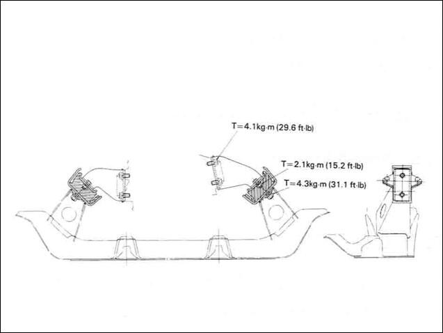
Thanks. In the absence of any other information, I had taken some measurements from a drawing that appears in the 1970 FSM (see below) and came up with 11.9 degrees... so I was close. Good to have this confirmation.
-
We all know that the Z's engine is canted off vertical. However, I've been unable to find any diagrams or tech info that indicates, definitively, what the cant angle is. Does anyone know the engine's cant angle? An, if so, what's your source?
-
An the compressed air was free!
-
Somewhere on this site, there's a video posted by @Patcon where he shows his technique for starting an L24 engine that (IIRC) had the carburetors completely removed. That may give some ideas for what you did wrong (or forgot to do). FWIW, it doesn't take much of a shot of starter fluid (spray) to light off an engine. You may have created a totally over-rich condition by being too heavy-handed with the spray bottle. That said, have you taken the steps to ensure that you've got a spark at each of the cylinders? This isn't hard to do. "Electrics first. Fuel second".
-
@AZ-240z Depending of course on whether you have the time and interest, a photo essay of the details of your car's engine compartment would be a great topic for a separate thread (maybe in the 'Resources' section?) It would certainly be a nice reference piece for other restorers.
-
According to my notes, the use of the 140psi gauge ended as of "1/71", somewhere around VIN 020000. This implies that the installation of the 90psi gauge began in Feb-1971. FWIW, the lowest and highest VIN's that I've seen for a 1/71 Z are, respectively, 018482 and 020500. That VIN range should be considered approximate (my VIN database is by no means complete), but the high-end number (which would align with end-of-month builds for January) is ~ 5000 units later than Lily's VIN of 014938 (11/70?) and coincides with a time when Nissan's production rate for the Z was ~ 2500 units/month. There were a lot other changes made to the car's detail design and equipment at the same time, but the "1/71" change date might have been a bit fluid from one item to another so that Nissan could use up existing inventory for the various affected parts. However, it seems unlikely that any of these changes would have pre-dated "1/71".
-
.jpg.c8701067b3383a94b6f69021f649a74c.jpg) Over the years, several CZCC members have produced write-ups on the topic of bringing an L24 engine back to life after a long period of storage. I think this one was the best of the lot, with credit to its Canadian author Phil _ (aka 'Blue', aka '240260280', aka 'Hoover'). I believe that this write-up originally appeared on the 'Atlantic Z-Car' website (still a great resource for how-to articles), but as of 2024 it seems to have disappeared. STARTING A DERELICT NISSAN L24-SERIES ENGINE – Author: 'Blue' Lubrication · Take the oil spray bar off and blast all of the holes with the straw of a can of carb cleaner. Spray into each hole then spray into the larger holes where the oil flows in from the cam towers. Do this until the bar is flowing clean solvent. Tilting the bar and flowing down helps. · Change the oil and pour extra oil over the valve train. Soak it good! · You should probably prime the oil pump. An easy way is to feed a clear vinyl hose into the oil passage behind the oil filter and run the line as far forward in the oil galley as you can. Connect a tight fitting funnel to the open end then hold high and pour oil into the funnel and let it drain into the hose (with the end now above the oil pump). · Remove plugs and turn the motor over by hand from the crank to ensure it is not seized. Electrical · If happy, hook up a remote starter and crank motor from passenger fender with valve cover off. Watch for oil coming out of the oiling bar. Make sure all holes are drizzling oil. It may take a while so make sure you have a good battery. You may have to prime pump more if oil does not come out after ~ 1 minute Spark · Once you have oil, check for spark and inspect the electrical system. You should have 12V at the coil when the key is turned to either ‘START’ or ‘ON’. Replacing plugs, distributor cap, and points is a good step, but if you have spark at the plugs, just change them to NGK's for now. Cooling · Drain radiator and flush engine with water and drain a few times. · You should change the rad hoses and interior heater hoses and water pump as soon as you can but it is not needed to start. Also look at the hose fittings when you pull off the hoses as they corrode to nothing. You should change the thermostat now. Fuel · Remove air cleaner from carbs (both cover, filter, and back plate) · Remove fuel hoses from fuel rail to fuel bowls, and from fuel rail to fuel pump · Remove carb bowl covers and make sure the needle valves are working. More carb cleaner will help. Make sure, though, that the needle valves do not have rubber tips (these types may swell up from solvent exposure) · Remove carb domes and clean with solvent (no abrasive). Keep front dome with front carb. Drain the oil in the plunger region. · Carefully remove piston and needle and clean. Again, no abrasive and be careful not to bend the needle. Keep front piston with front carb. · Clean carb body · Remove the small hose between the fuel bowl and jet on each carb and make sure they are not collapsed or filled with tar. Replace if required. · Unscrew the choke lifting arm from each jet and remove each jet. Use proper fitting screw driver and press in firmly when turning. · Clean each jet with carb cleaner (inside passage and outside). Scrub the brass tube’s outer surface with a Scotch-brite pad until it shines. · Clean the passage in the carb body where each jet fits. Test-fit each jet in its passage and make sure it can slide up and down with no binding. · Turn the knurled knob under each carb all the way up until it stops. You may need to spray some penetrating oil on these from below to get them loose. You can turn them up and down to work loose. Some carbs have a safety stop underneath that you can remove for the moment · Once the knurled knob turns freely and you have turned it all the way up, turn back down 2.5 turns. Use the big bump on the knob to measure turns. You may have to feel for it. · Reinstall the safety stop and leave ~ ¼” to ½” between it and the knurled knob. · Reinstall the jet and connect the choke rod to it. However, disconnect the choke cables for the moment. Make sure the jets lift all the way up. When you look into both carb bodies the tops of the jets should be seen to be the same distance down in the tube ~ 2.5mm (one turn = 1mm, so 2.5 turns) if you measure the depth. · Reinstall the pistons and needles in their proper carb body. · Reinstall dome (w/o plunger) while carefully lifting and dropping the piston with the finger of your other hand in the front carb hole. The piston should drop all the way to the bridge with no binding. Try to tighten all 4(or all 3) screws evenly, rather than just 1 at a time. In order to remove piston binding, you may also have to twist the dome CW or CCW as you tighten the screws. · Install plungers but no oil. · Clean fuel bowls · Install new hoses from fuel bowls to jet. Make sure they don't kink. · Install fuel bowl lids. · Remove hoses to fuel rail and clean the fuel rail by spraying carb cleaner through it. Spray into both delivery and return holes. (Note: The small return line has a fixed orifice at the end and this must not be clogged). · Install new hose from fuel pump to fuel rail. · Install new fuel filter · Install new hose from fuel filter to fuel pump · Run two 6' fuel lines from fuel filter (delivery/output) and from fuel rail (return) into a gas-filled jerry can sitting next to passenger wheel. · With plugs out, crank the motor to drive fuel pump and send fuel to fuel bowls. Check for fuel in bowls. Check for no leaks in hoses. Check for no fuel bowl overflows. Start · You are now ready to test start! · Install plugs and have fun. · Do a valve adjustment after it heats up. · Measure compression to get an idea of how well it is sealing. · After it’s run for a while, fill the carb damper tubes with 20W oil (3-in-1 oil in blue container also works fine) · Forget about using car’s own gas tank until you remove it and clean it. It is probably very rusty and varnished inside. You will be left on the side of the road if you try to use the tank. Also: Replace the flex hoses (and clamps) between the tank and hard lines. While you’re doing this, splice an in-line disposable fuel filter into the supply-side hose.
Over the years, several CZCC members have produced write-ups on the topic of bringing an L24 engine back to life after a long period of storage. I think this one was the best of the lot, with credit to its Canadian author Phil _ (aka 'Blue', aka '240260280', aka 'Hoover'). I believe that this write-up originally appeared on the 'Atlantic Z-Car' website (still a great resource for how-to articles), but as of 2024 it seems to have disappeared. STARTING A DERELICT NISSAN L24-SERIES ENGINE – Author: 'Blue' Lubrication · Take the oil spray bar off and blast all of the holes with the straw of a can of carb cleaner. Spray into each hole then spray into the larger holes where the oil flows in from the cam towers. Do this until the bar is flowing clean solvent. Tilting the bar and flowing down helps. · Change the oil and pour extra oil over the valve train. Soak it good! · You should probably prime the oil pump. An easy way is to feed a clear vinyl hose into the oil passage behind the oil filter and run the line as far forward in the oil galley as you can. Connect a tight fitting funnel to the open end then hold high and pour oil into the funnel and let it drain into the hose (with the end now above the oil pump). · Remove plugs and turn the motor over by hand from the crank to ensure it is not seized. Electrical · If happy, hook up a remote starter and crank motor from passenger fender with valve cover off. Watch for oil coming out of the oiling bar. Make sure all holes are drizzling oil. It may take a while so make sure you have a good battery. You may have to prime pump more if oil does not come out after ~ 1 minute Spark · Once you have oil, check for spark and inspect the electrical system. You should have 12V at the coil when the key is turned to either ‘START’ or ‘ON’. Replacing plugs, distributor cap, and points is a good step, but if you have spark at the plugs, just change them to NGK's for now. Cooling · Drain radiator and flush engine with water and drain a few times. · You should change the rad hoses and interior heater hoses and water pump as soon as you can but it is not needed to start. Also look at the hose fittings when you pull off the hoses as they corrode to nothing. You should change the thermostat now. Fuel · Remove air cleaner from carbs (both cover, filter, and back plate) · Remove fuel hoses from fuel rail to fuel bowls, and from fuel rail to fuel pump · Remove carb bowl covers and make sure the needle valves are working. More carb cleaner will help. Make sure, though, that the needle valves do not have rubber tips (these types may swell up from solvent exposure) · Remove carb domes and clean with solvent (no abrasive). Keep front dome with front carb. Drain the oil in the plunger region. · Carefully remove piston and needle and clean. Again, no abrasive and be careful not to bend the needle. Keep front piston with front carb. · Clean carb body · Remove the small hose between the fuel bowl and jet on each carb and make sure they are not collapsed or filled with tar. Replace if required. · Unscrew the choke lifting arm from each jet and remove each jet. Use proper fitting screw driver and press in firmly when turning. · Clean each jet with carb cleaner (inside passage and outside). Scrub the brass tube’s outer surface with a Scotch-brite pad until it shines. · Clean the passage in the carb body where each jet fits. Test-fit each jet in its passage and make sure it can slide up and down with no binding. · Turn the knurled knob under each carb all the way up until it stops. You may need to spray some penetrating oil on these from below to get them loose. You can turn them up and down to work loose. Some carbs have a safety stop underneath that you can remove for the moment · Once the knurled knob turns freely and you have turned it all the way up, turn back down 2.5 turns. Use the big bump on the knob to measure turns. You may have to feel for it. · Reinstall the safety stop and leave ~ ¼” to ½” between it and the knurled knob. · Reinstall the jet and connect the choke rod to it. However, disconnect the choke cables for the moment. Make sure the jets lift all the way up. When you look into both carb bodies the tops of the jets should be seen to be the same distance down in the tube ~ 2.5mm (one turn = 1mm, so 2.5 turns) if you measure the depth. · Reinstall the pistons and needles in their proper carb body. · Reinstall dome (w/o plunger) while carefully lifting and dropping the piston with the finger of your other hand in the front carb hole. The piston should drop all the way to the bridge with no binding. Try to tighten all 4(or all 3) screws evenly, rather than just 1 at a time. In order to remove piston binding, you may also have to twist the dome CW or CCW as you tighten the screws. · Install plungers but no oil. · Clean fuel bowls · Install new hoses from fuel bowls to jet. Make sure they don't kink. · Install fuel bowl lids. · Remove hoses to fuel rail and clean the fuel rail by spraying carb cleaner through it. Spray into both delivery and return holes. (Note: The small return line has a fixed orifice at the end and this must not be clogged). · Install new hose from fuel pump to fuel rail. · Install new fuel filter · Install new hose from fuel filter to fuel pump · Run two 6' fuel lines from fuel filter (delivery/output) and from fuel rail (return) into a gas-filled jerry can sitting next to passenger wheel. · With plugs out, crank the motor to drive fuel pump and send fuel to fuel bowls. Check for fuel in bowls. Check for no leaks in hoses. Check for no fuel bowl overflows. Start · You are now ready to test start! · Install plugs and have fun. · Do a valve adjustment after it heats up. · Measure compression to get an idea of how well it is sealing. · After it’s run for a while, fill the carb damper tubes with 20W oil (3-in-1 oil in blue container also works fine) · Forget about using car’s own gas tank until you remove it and clean it. It is probably very rusty and varnished inside. You will be left on the side of the road if you try to use the tank. Also: Replace the flex hoses (and clamps) between the tank and hard lines. While you’re doing this, splice an in-line disposable fuel filter into the supply-side hose. -
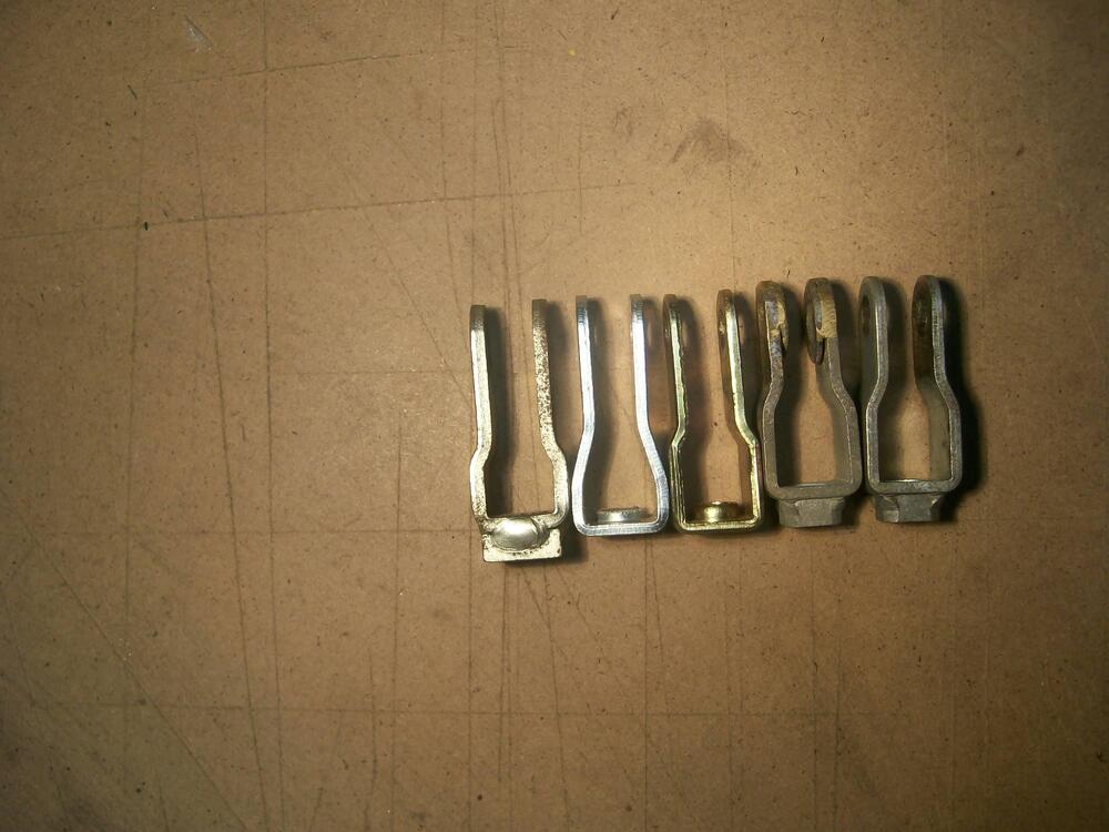
I don't recognize these two parts. What are they?
-
71z but L28 engine, could someone tell me what I have?
Namerow replied to tsunami's topic in Open Discussions
The coding system for the numerals makes sense. However, what is the purpose of the letter? For example, the coding for an engine block in my possession is '2329N'. The engine was removed from a Z produced in April 1972 (VIN 079701) and its number (101275) matches the number shown on the ID plate taken from the engine compartment. If I understand correctly, '2329' indicates 29-March-1972. But what does the 'N' mean? -
Great stuff! We Canadian Z-car supporters have a special role in the car's history and it's reflected in these print materials. Can you maybe show us the full brochure? I like the slightly-modified side-view graphic of the Z. It looks slightly Cheetah-ish (terrible race car, great Cox slot car). BTW, I just noticed the dealer stamp on the brochure ('Terry Maher - Organ Datsun Limited - 2038 Dundas St. East, London, Ontario'). London is my hometown. I lived there until I finished my undergrad engineering studies at Western in 1972. I have zero recollection of a dealer called Organ Datsun. Which is not to say that they didn't exist. Instead, it points to how low-level the Datsun Canada dealer network was at the time when the Z was reaching (arguably) its pinnacle year in the international marketplace.
-
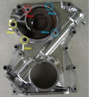
Recommend that you use an impact driver* to free up the bolts. To gain the required access, you'll need to drain the cooling system and remove the radiator. (* Do not use an electric or pneumatic impact driver. Use the good-old-fashioned, hammer-blow type. It may take a bit more time and effort, but it prevents overpowering the bolts. A high-torque power impact driver will snap those long bolts just as surely as you leaning on them too hard with a wrench.) Here's a picture of what you'll be working with. The numbers refer to the wrench size... x The pump is secured by a total of five bolts. Three of these also help to secure the Timing Cover to the front of the engine block. The small-head bolts at 1 o’clock and 4 o’clock are short and thread into the cover – M6 (10mm wrench) The large-head bolts at 7 o’clock and 9 o’clock are long and fat and thread into the block – M8 (12mm wrench) The small-head bolt at 11 o’clock is long and skinny and also threads into the block – M6 (10mm wrench) The long, skinny bolt @ 11 o'clock is usually the one that snaps off when removing or tightening. The rad, pulley, pump, and the timing cover will all have to come off to get the access needed to extract the remains. Removing and reinstalling the timing cover will open up the potential for oil leaks where it meets the oil pan. In other words, there's going to be a high price to pay if you snap off one of these water pump bolts. It doesn't need to happen... but it very well may if you try to rush the job and use too much tool and not enough caution.


-
Parts Manual shows that the PN changed as of Aug-1973. I wonder if this production date also marked the introduction of factory-installed air conditioning (as opposed to dealer-installed)? If hat was the case, the extra opening might have been added to provide a dedicated pass-through for AC-related lines and hoses.
-
Why was the fourth hole added on the left side?
-
The mainstream Canadian automotive 'industry' has always been premised on business activities restricted to 'sales, service and marketing' (SSM). Canada-based manufacturing activities, where they apply (ref. GM, Ford, Chrysler, Honda, and Toyota), are operated as separate corporations with separate management. The 'GM Canada' that we all know is actually an SSM-only operation, incorporated as 'General Motors Canada Limited'. The manufacturing operations in Oshawa (vehicle), Ingersoll (vehicle) and St. Catharines (powertrain) are controlled by a division of the General Motors Corporation parent in the US. I'm pretty sure that the same split-business model is used by Ford, Toyota and Honda for their Canada-based operations. The OEM's who don't have Canada-based manufacturing operations (e.g. Nissan) operate here strictly as SSM businesses. SSM activities include such things as determining which models, trim levels, and option packages will be offered for sale in Canada, as well as the equipment list and pricing for each of those trim levels and option packages. That pricing activity also includes setting the amount for the 'delivery' charge. SSM also: Controls dealer liaison (the dealers are independent businesspeople who hold sales/service franchises with the OEM) and set and monitor dealer performance standards (e.g. mandatory signage standards). Develops the marketing program for each of the vehicle lines on offer. That includes developing (c/o outsourcing to major communications companies like McLaren and Cossette) all of the print and electronic materials used to support the marketing, sales and distribution of the vehicles. Those materials include unique-Canada items such as TV/ online advertising, print ads, dealer showroom materials (brochures, etc), and (in most cases) the owner manuals that are provided with each vehicle. That said, the owners manuals and warranty booklets for the Z were printed in Japan up until at least the 1972 models AFAIK there are, and always have been, only two versions of these Canadian marketing/sales-support materials: the English version and the French version. However, since the advent of the internet (and certain federally-mandated requirements for the way the OEM's are permitted to display pricing), each manufacturer's Canadian website requires the user to declare their province of residence before it will display any pricing. This permits province-to-province differences for PST and delivery to be factored into the 'all-in' price. Back in the day, I think that the Canadian Datsun SSM activities were initially based in BC (New Westminster?), before transferring to Toronto. It would be interesting to know if that early 1969-70 Z brochure was made available in both English and French versions. It would also be interesting to know whether there was ever a French-language version of the Z owners manual.
-
Interesting question. I decided to turn AI loose to get an answer. Here's what I found: The Monroney sticker, also known as the window sticker, is a label required in the United States to be displayed in all new automobiles. It includes certain official information about the car, such as pricing, equipment, and fuel economy details1. But why didn’t Canada adopt a similar sticker system? Let’s explore: Historical Context: In 1955, Senator Almer Stillwell “Mike” Monroney chaired a subcommittee that investigated complaints from U.S. car dealerships about abusive treatment by manufacturers. Dealers could inflate the manufacturer’s suggested retail price, leaving buyers unaware of the actual cost and options1. To address this, Monroney sponsored the Automobile Information Disclosure Act of 1958, which mandated information disclosure for all new automobiles sold in the U.S. This act required the Monroney sticker to be displayed on new cars1. Canada’s Approach: Canada did not adopt the Monroney sticker system for several reasons: Regulatory Differences: Canada has its own regulatory framework for vehicle informationdisclosure. Instead of a single standardized sticker, Canadian provinces and territories have their own requirements for vehicle information, including pricing and safety features. Market Size: The Canadian automotive market is smaller than the U.S., which may have influenced the decision not to implement a nationwide sticker system. Industry Practices: Canadian dealerships and manufacturers may have relied on other methods to provide information to consumers, such as brochures, websites, and sales representatives. Consumer Awareness: Canadian consumers may have been more familiar with alternative sources of information, reducing the need for a standardized sticker. Canadian Vehicle Information: While Canada doesn’t have a Monroney sticker, pre-owned vehicles must have a Buyers Guide sticker as mandated by the Used Car Rule of the Federal Trade Commission. This decal informs buyers about warranties or indicates that the pre-owned car is being sold "as is". So: It looks, to me, like another example of how Canada and its bush league politicians have dropped the ball for decades as they've skirmished over inter-provincial trade issues. As Canadian citizens, we all end up as losers because of this (continuing) parochialism. It's possible that some of the provinces may have (or have had) a window-sticker rule in place -- but I doubt it. I worked for GM Canada CHQ (Canada Headquarters) from 2004 - 2010 as a product training specialist. I don't recall ever having to deal with window stickers for any of the new-stock vehicles that we used for dealer training programs carried out across the country. Prior to that, I worked for about ten years in a similar role in the USA for GM and Mercedes-Benz and the new-stock production vehicles used for training purposes always came with a Munroney sticker.
-
280z Auto to 5 Speed swap-- Clutch pedal height
Namerow replied to sboy79's topic in Engine & Drivetrain
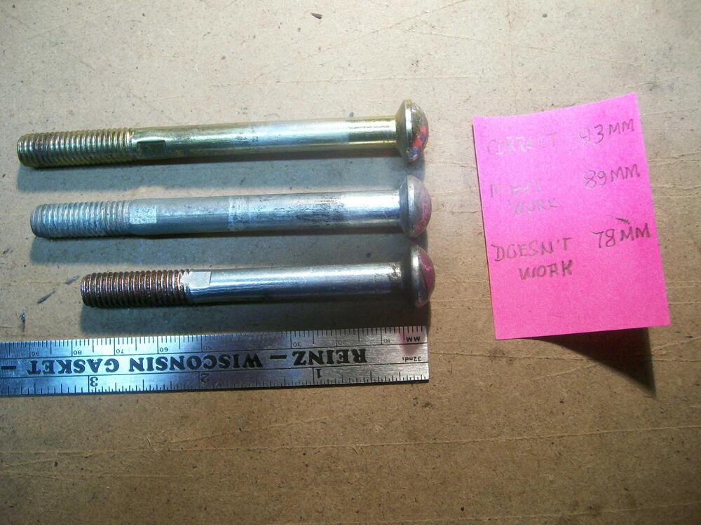
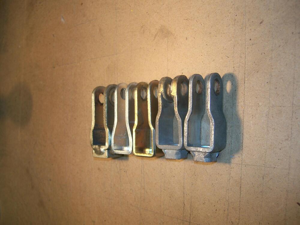
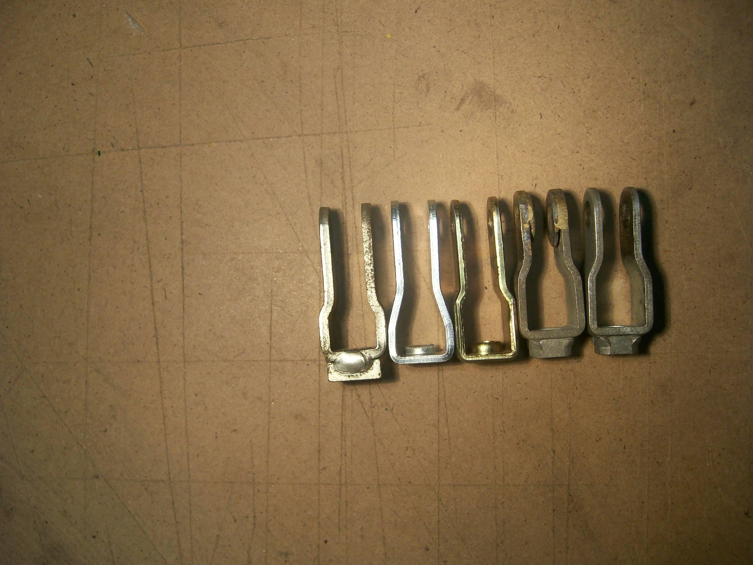
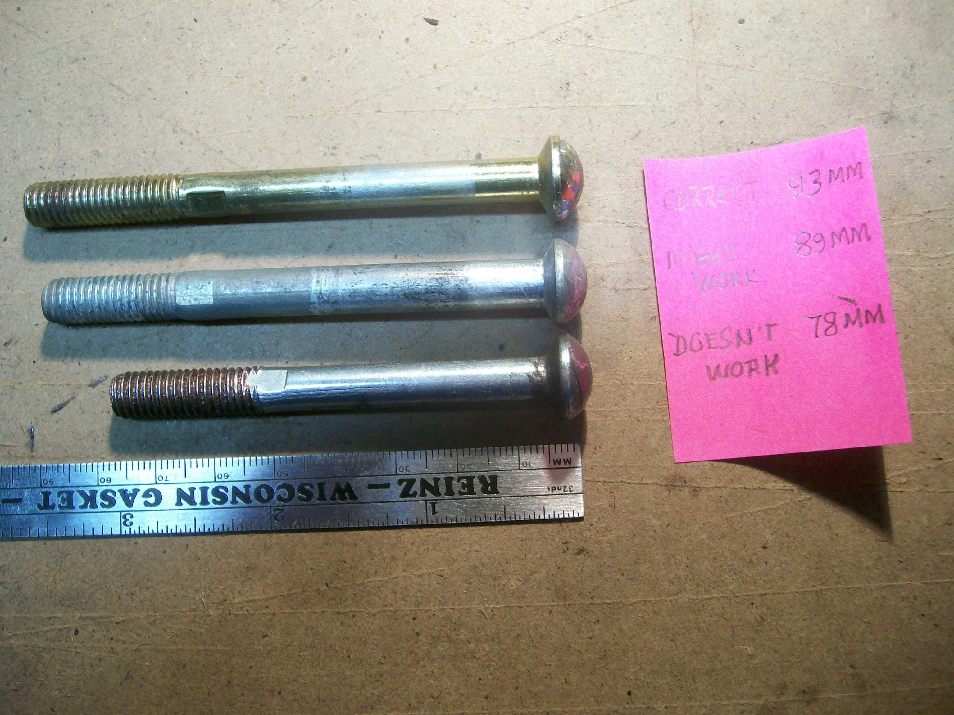
These three photos may provide some additional insights... although they may just add to the confusion. I have four master cylinders and two Mastervacs in my parts collection. I've discovered that these have provided me with three different pushrod designs and three different clevis designs (although I can't say for certain whether they're all Nissan OE parts). Mixing them up creates the potential for 9 different geometries...