Namerow
-
Posts
1,483 -
Joined
-
Last visited
-
Days Won
23
Content Type
Profiles
Knowledge Base
Zcar Wiki
Forums
Gallery
Events
Downloads
Store
Blogs
Collections
Classifieds
Everything posted by Namerow
-
 That's a nice-looking car. Like the wheels. Your leather seat covers with the contrasting stitching help to liven up the interior 🙂.
 -
Work is coming along nicely. Just noticed your Volvo Hatch in the driveway. I always liked these -- except for the Interior (the word 'plain' doesn't do it justice).
-
Version 1.0.0
16 downloads
This set of .pdf files can be used to print full-size templates for all of the various foam gaskets used in the 240Z Series 1 Heater and Blower assemblies. These are a companion piece to my separate article on rebuilding the Heater and Blower. The article provides recommendations for the types of materials that should be used to create the various gaskets.Free -
My two swiss S30Z Fairlady Restoration build thread
Namerow replied to JDMjunkies.ch's topic in Build Threads
Looking at Photos #1 - #3, it appears that part of the shop's technique for the floor pan replacement was to first cut away a 'skirt' from the transmission tunnel and then, working off the vehicle, fit and weld that to the KFV panel before installing the finished result in the car. I suppose that would give a perfectly-shaped welding seam along the top of the 'skirt', but I wonder how they judged the alignment of the skirt relative to the KFV panel before joining the two pieces during the off-vehicle procedure (similar to what seems to be going on in Photo #1)? -
My two swiss S30Z Fairlady Restoration build thread
Namerow replied to JDMjunkies.ch's topic in Build Threads
Interesting photo, to say the least! -
I'm going to speculate that these little 'dents' were used as master positioning markers. If so, were they created to guide the panel-stamping/forming process? Or, instead, were they used to guide and/or check the positioning of the stampings in their jig prior to welding? The latter seems more likely. One wonders, then, what prompted the change in orientation of the dent in the rear floor deck stamping after less than 100 units had been assembled. Perhaps the performance of the assembly jig in its original design iteration wasn't delivering adequate results, making this small-but-important change necessary before the production process ramped up to full speed.
-
Are these 'door lights' the ones that appear in the Parts Manual (Electrical - Step Lamp and Map Lamp) as PN 26420-E4100 ?
-
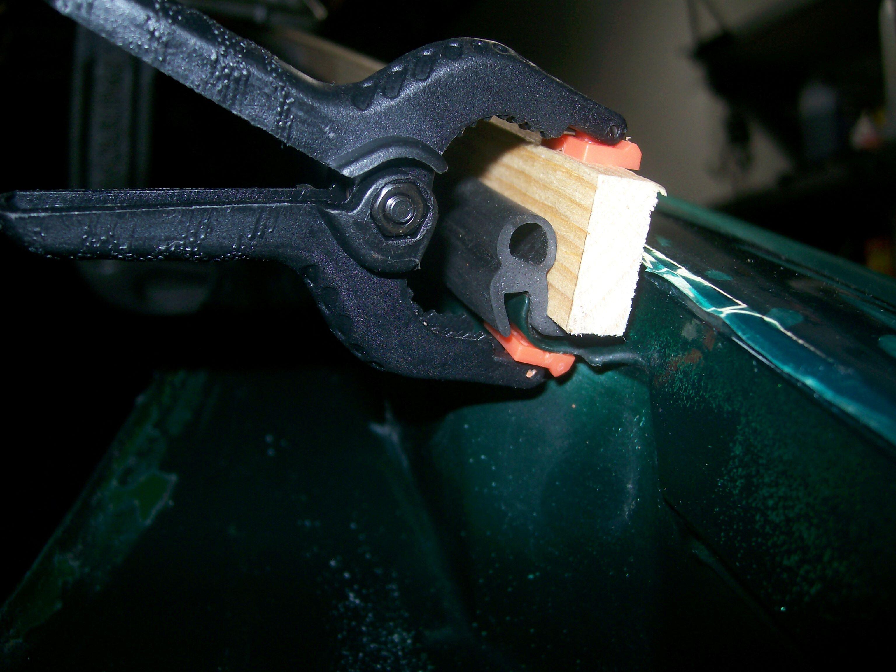
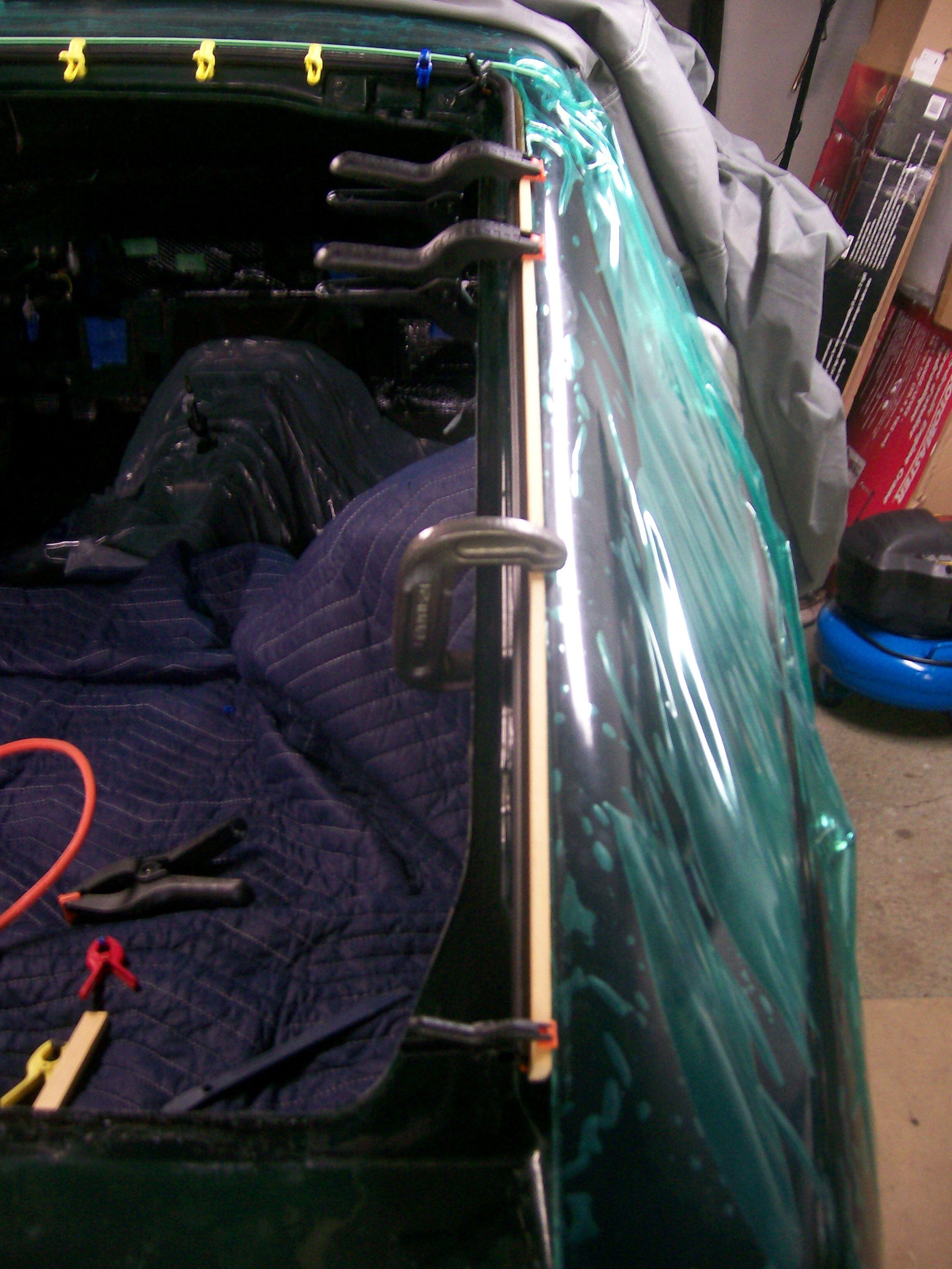
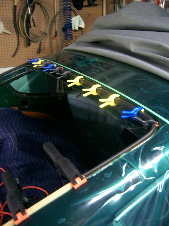
Here are three photos from my installation. A length of 1 x 2 clamped along the side channel helps to distribute the clamping force. The plastic pinch clamps are cheap and worked nicely.


-
There's lots of discussion and photos available on this site concerning the Z's early and late hinge designs. The early design was a little crude (articulating 'leaves' or 'blades', with a spring that supplied a bit of resistance when closing the door) and lacked any type of provision for stabilizing the door in a partly-open position. More critically, the leaves could go over-centre if the door was forcefully thrown open by a gust of wind (I believe that the spring would pop out in the process, too). Once this happens, there's no convenient way to get the leaves to reverse back over centre. Any attempts at strong-arming the door to get it closed again would bend the leaves. The later hinge design works pretty well, although lack of maintenance (lubrication) will cause the roller pin to wear out prematurely. There's a thread here on the site that details the rebuilding process for the later-style hinges.
-
Nice photo. Boy in the front is making engine noises, right?
-
You say, 'also'. Were the 4 captive fasteners installed only on cars fitted with automatic transmissions? And the doubler panel as well?
-
It's possible that it was left there so that it could be bent back into place and welded/finished so as to return the car to 'stock' configuration at some point in the future. Or maybe it was just laziness.
-
Nice photo essay. Well done. If you or anyone else has the opportunity, a similar presentation for the rocker panel area would be a great assist for other restorers.
-
Good question. Perhaps they're used to secure the special finisher plate used on cars with the automatic transmission? The cutback in the tunnel sheet metal was a common solution for those who installed 5-speeds. As it stands, you may find that your knuckles come close to colliding with the dash trim when you select 1st, 3rd, or 5th gear. One solution is to fabricate a modified shift lever with a 'S' bend down low so that the upper part of the lever is moved about an inch to the rear. This will also allow the sift lever to better align with the outer shift boot. The 'extra' plate is, I believe, just a doubler sheet, used to provide a little extra stiffness for this region of the transmission tunnel (otherwise weakened by the cutout for the shift lever).
-
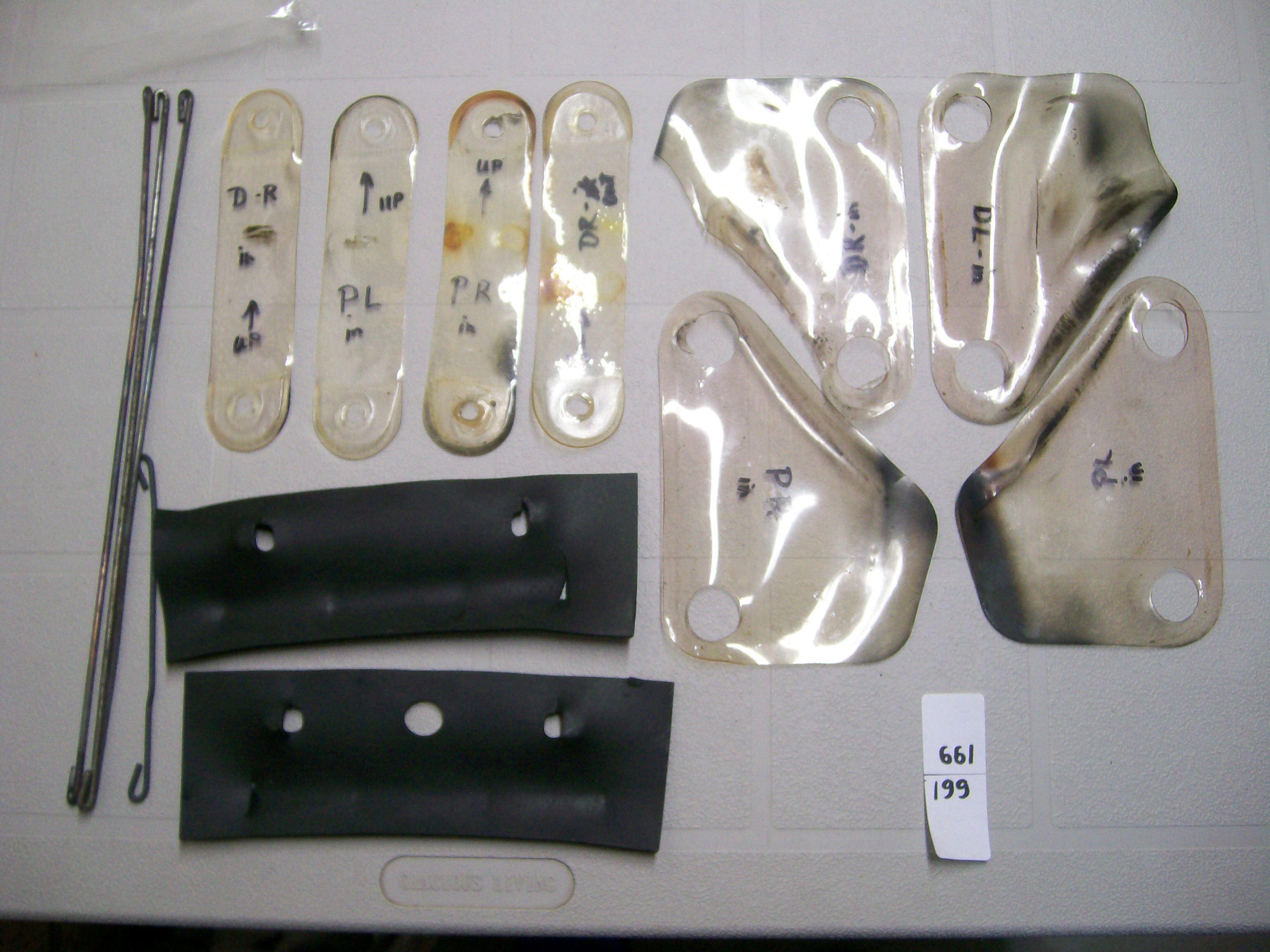
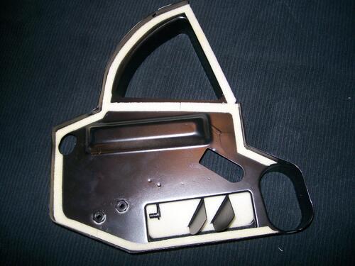
I did. The originals, although intact, were stiff and discoloured. I found some clear vinyl sheet of suitable thickness and made new ones, using the old protectors as templates.

-
Correct. And just confirmed c/o Parts Manual, which shows distinct PN's for the LH and RH 'slide assembly with lever'. These are mirror images of one another, such that the lever's shaft runs along the inboard length of each seat and the lever arm points outboard on both (makes it convenient to operate for right-handed drivers of LHD cars, but not so good for left-handers like me).
-
A dry-cleaner's bag works nicely. Just slip it over the entire seat back and trim to length. Makes it much easier to install the new seat cover. A bit of talc powder can also be used to assist.
-
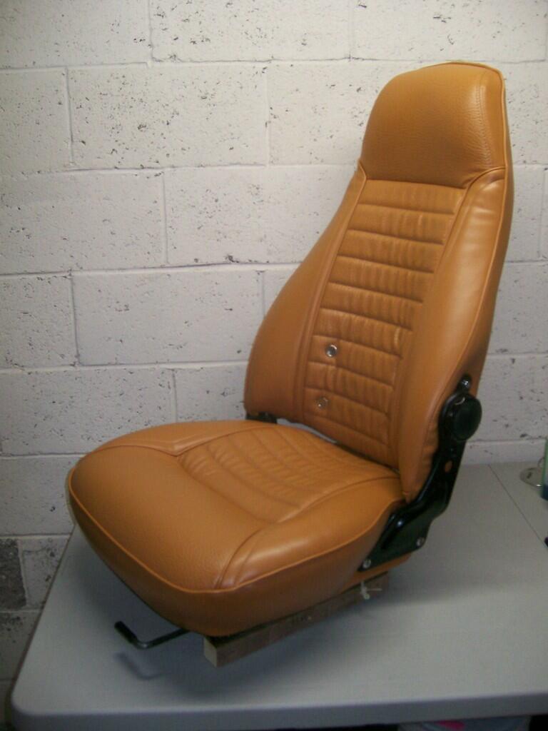
Nice job. I used Distinctive Industries' covers when re-doing the seats for my 70 Z. I did not purchase new foam b/c the OE foam still seemed in good shape. Long story short, I found the fit of the new covers to be a bit baggy. Things improved a lot with the addition of 1/2" and 1/4" foam sheet in strategic locations (esp. the front and side bolsters), along with pushed-into-place 'basting' material (bought at a dressmaker's shop) that helped to remove/reduce wrinkles in certain locations. I was pretty happy with the end result, esp. considering the fact that this was my first-ever venture into the world of automotive upholstery. FWIW, hot rod and boat shops can provide a lot of guidance for this type of work.

-
Excellent photos. Thanks for posting. It is, indeed, a complicated joint. I'm always impressed by the skills of the manufacturing engineers and designers who (with little credit) develop such schemes and make them ready for mass-production. I've often wished for 'exploded view' explanations of how the contributing panels come together at complex joints such as this one (another good example is the 'dogleg' behind the lower-rear door area). Unfortunately, it would require either: a) an informed industrial artist (similar to the person who created the drawings in the parts manual), or; b) a photographer in possession of all of the individual panels/stampings. Alas, the chances of either happening is remote.
-
Does anyone have a picture of how the roof and rear quarter panels come together when the latter is replaced. Failing that, maybe just a detail shot of the relevant area of the rear quarter panel. There has to be a weld somewhere!
-
That makes sense.
-
And yet... Hard for me to believe that a broad-surface soldered joint like this one would offer structural flexibility sufficient to absorb the amount of distortion that would cause the windshield to pop out of its frame (which, we should remember, is lined with a compliant rubber seal). Not disputing Mr. Matsuo's claim, but I wonder whether the flexibility that he spoke of had more to do with positioning flexibility (compared to spot welding) for the two parts during and just after the joining process*, rather than after the car hit the road. Put another way, just how much would that joint need to 'give' in order to prevent the amount of windshield frame distortion needed to make the windshield pop out: 1/16"? Is that soldered joint really capable of absorbing 1/16" of relative shear without breaking?
-
Transmission Tail Shaft Break-out Repair ideas
Namerow replied to zKars's topic in Engine & Drivetrain
Nicely done. We should all have milling machines and lathes in our workshops! -
Transmission Tail Shaft Break-out Repair ideas
Namerow replied to zKars's topic in Engine & Drivetrain
Counter-thought: You say that you have a mill. Cut off the end of the housing at a point just past the deepest part of the gouge. Now mill out the ID of the remaining housing wall to half the original thickness. Make the milled-out area as deep as you can. Find some aluminum pipe with about the right ID and OD. Machine outside and inside surfaces to get the correct final ID and OD. Now cut a stepped-down length of OD to match the ID of the undercut that you created in the housing. Aim for an interference fit, where your new piece would be chilled and the housing heated before assembly. Maybe add a few drop of the appropriate type of Loctite for extra security. It's hard to see from your photos whether the stub of good housing that sits below the gouged out section would be deep enough to make this sleeve approach work reliably. I would think that a drop-in length of 1/2" would be adequate. -
Just placed my order!