Namerow
Community Member
-
Joined
-
Last visited
Everything posted by Namerow
-
For the 1970 - 73 models, it should be located on the left-side kick panel, just under the dash ('left' as viewed looking forward). From my notes (copied from someone else's notes): Terminal markings and wire connections at the Relay: B = Battery >> Green/Red wire H = Horn >> Green wire S = Switch >> Green/Black wire The Green wire is the one that is switched internally in the Relay. The Green/Black wire connects back to the Horn Button on the steering wheel. It works by grounding the circuit*. The Green/Red wire supplies power from the battery via the Fuse Box (4th fuse down on the Left side, 10A). (* There is a contact ring located under the Horn button. A wire runs from the contact ring to the front of the steering wheel. When you push the horn button, the front ring makes contact with the steering column, completing the path to ground.) If I had to guess, your problem will be with the switch contacts in the Horn pad and not with the Relay. But you never know. The attached wiring diagram (in colour!) was created a few years back by a gentleman named Sully Ridout and contributed to this site. It's appropriate to the 1972 N. American models, so it may not be exactly right for a European Z (other member located in Europe can probably comment). However, it may help you to figure things out for the horn circuit at least. S30 Wiring Schematic - 72 240Z - Colour (by Sully Ridout).pdf
-
-
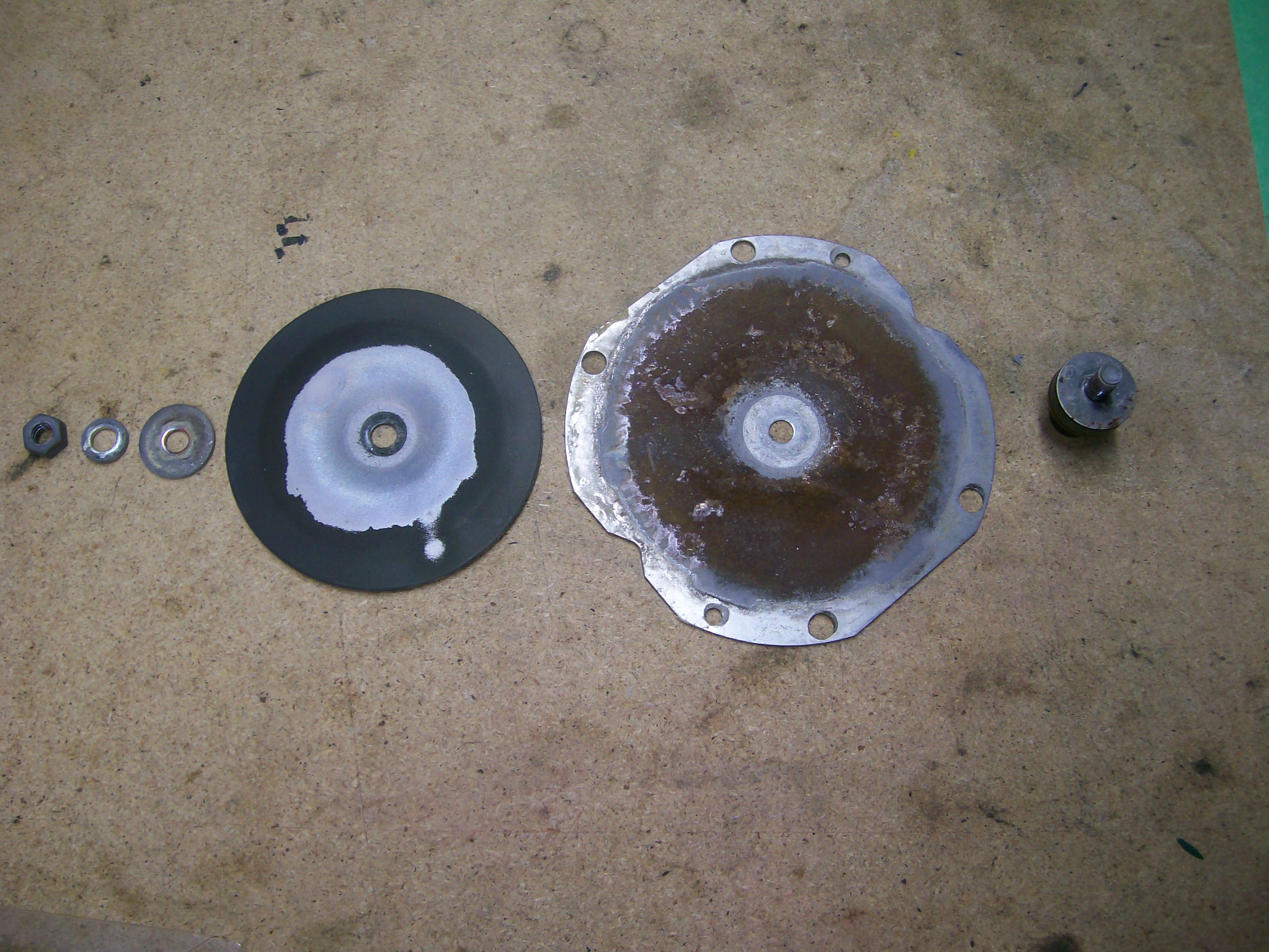
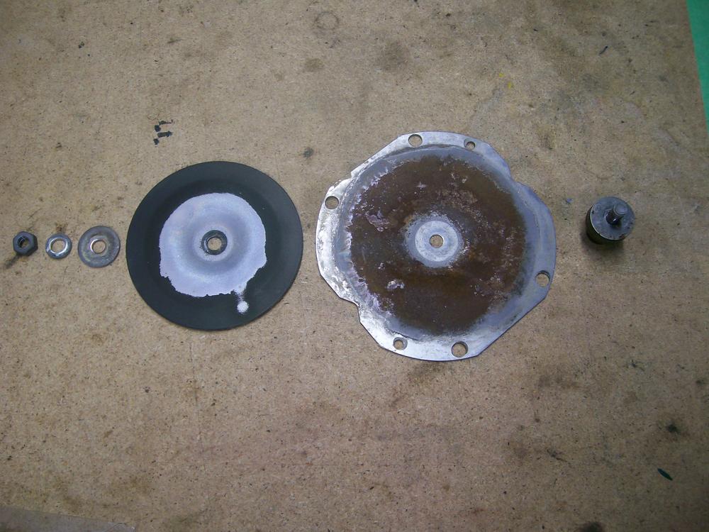
If you buy a remanufactured unit, inspect it carefully before you leave the store. At least one member here (Grannyknot) reported that his remanufactured MasterVac showed damage to some of the 'teeth' on the lip of the housing (probably from poor handling during disassembly at the rebuild shop), to the point where he had concerns about its vacuum integrity. I think one of the threaded studs was marginal, too.
-
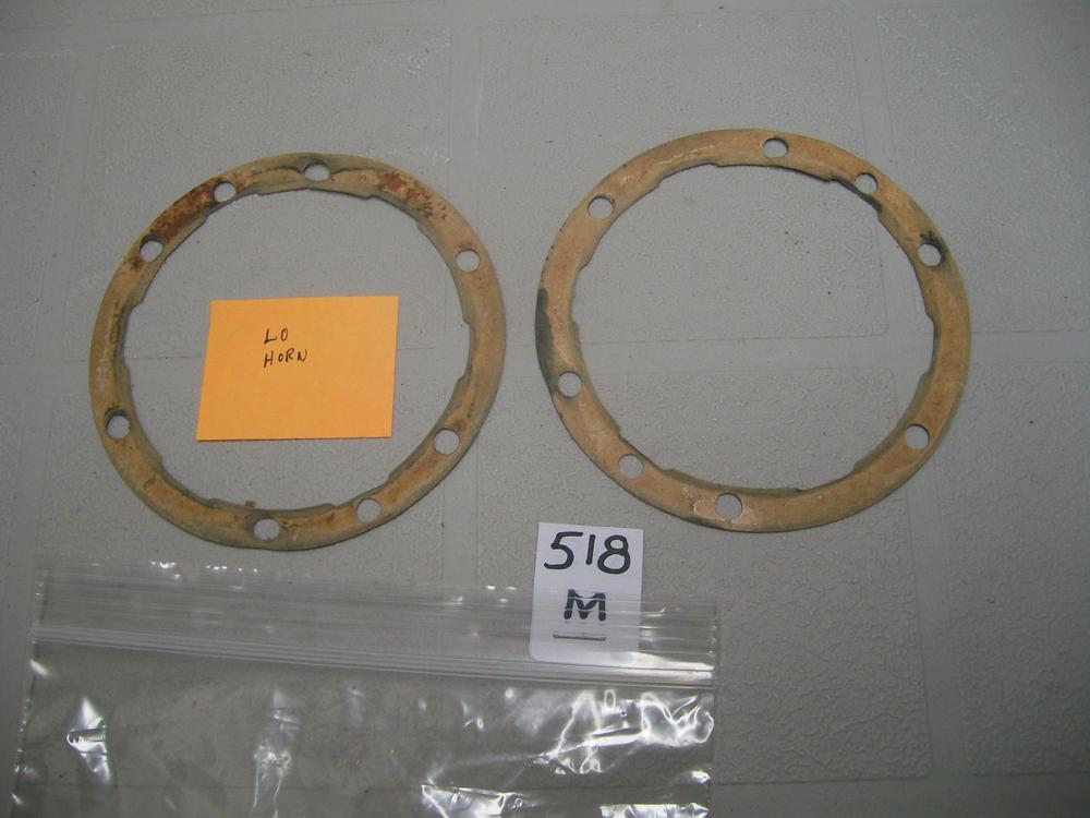
... or make your own gaskets. I made mine using butcher's paper. About the right thickness and somewhat waterproof. Zup's successful experience using no gaskets at all suggests that they contribute nothing to the acoustic performance, so maybe they were intended to be a moisture seal (albeit, not very effective -- see picture). So maybe a thin bead of silicone gasket material on each mating face would be the easiest and most effective solution. If, for any reason, the sealant snubs the sound output, you can always strip it off and try something else.
-
Serendipity, my friend. I remember the' authoratative' blast of my distinctly non-USA, two-tone Z horns delivered when I was a 1970's driver . When I rebuilt the horns from my 70 Z, I was shocked (as in underwhelmed) by what I heard. I love the nostalgia effect, but for the guerilla driving conditions where I now live, they need modern-tech, hi-volume reinforcement.
-
Not sure about this. I bench-tested my re-built horns independently, off the car, with direct pos and neg connections from a guaranteed 12VDC power supply. They had to be correctly adjusted with the adjustment screw. Move too far in either direction and 'bleat' became 'dink'... or silence.
-
I got mine (in 2015) from my local NAPA outlet. 6" canister, measured with my vernier caliper. Might have just got lucky, but don't overlook the obvious.
-
I hate anecdotal evidence, but I will say again that the variable with the most pronounced effect in my plating experience was the regular addition of of the Caswell 'brightener' liquid to my electrolyte bath. I don't know why. I have no formula or explanation to offer. Alchemy! Sorcery! I too want a Caswell franchise where I can sell overpriced, unexplained chemicals to optimists just like me.
-
It would be best if the comparison testing was done on the same dyno. Otherwise, the (probably) small differences measured could have to do as much with dyno A vs. dyno B as they do with exhaust system X vs. exhaust system Y. I haven't looked at chassis dyno specs for a long time, but back in my day, the best chassis dynos that speedshops could afford were based on eddy-current absorber technology and IIRC the absolute accuracy was on the order of +/- 5% . Decent repeatability, but only so-so absolute accuracy. The automotive and fuels/lubricants industry R&D labs that I worked with used controllable DC machines, where the accuracy was +/- 0.5%. Those units cost anywhere from $500K to $1 Million. The low-end machines may be better than they used to be, but it's always best to be using the same measurement device if you're looking to detect small differences with confidence.
-
Agree with Grannyknot and Patcon. Maybe it's that clean northwest coastal air. Can I send you a box of my parts that still need plating?
-
If you play with the adjustment screw (X-type panhead machine screw at the 11:00 o'clock position in your picture of the rear face of your horn), you may find an easy solution to your problem. If not, no harm done and you can move on to the next step of your troubleshooting. The adjustment is a bit hair-triggered and requires a little patience to get it right. If your car's PO played with this and lacked patience, he might have just given up and left it in the 'dink' adjustment zone.
-
Don't fret about the gaskets. They're just made from coated paper.
-
I don't have a picture, but my results are pretty much identical to the pix just posted by Siteunseen. It's a 'whiter' look than the OE finish. As an engineer, I respect the advances made in paint chemistry but I'm still skeptical about whether a paint can get the job done in high-visibility underhood applications. Diseazed says his experience supports VHT paint for this application. All I care about is good solutions for all of us. Anyone else with similar positive experiences with VHT paints?
-
Of course it looks beautiful. But that's only as long as you never touch it with oil, fuel, or any kind of cleaning solvent.
-
The FSM has some surprisingly detailed instructions on how to tune the horns. Personally, I found the results no better than 'ok', Nevertheless, you should be able to adjust so that you at least get a 'bleat' rather than a 'dink.
-
I blast-cleaned my cover using fine-grit glass. Afterwards, I dressed it with 'Gibbs' brand fogging oil (aka 'snake oil'). I'm happy with the result, but it is not an OE look. If you want that, it looks like vapor bla$ting is the way to go. The OE appearance looks 'harder' than what you'll get with typical media blasting, although walnut shells might come closer.
-
Many years ago, I was invited to make an inspection tour of a government research facility (big building, big test rigs). It was located about a mile away from two steel mills, separated from them by an open harbor. The facility manager showed me a bunch of expensive electrical panel that he said had been ruined by the SO2 carried in the air from across the harbor.
-
The two manifolds on the L24 engine are shown in the parts diagram to be secured with studs at all seventeen locations. However, the engine in my 70 Z uses bolts for the top row (six locations). A spare L24 engine (from a 72 Z that I had as my daily driver back in the 1970's) also used bolts for the top row. I'm 90% certain that the head and manifolds on that car had never been removed for service (I was the 2nd owner and bought it in 1976 with only ~ 40,000 miles on the odometer). The bolts used on both my engines show similar markings on the bolt heads. Comments or insights, anyone?
-
Don't feel bad. My two-year project is now entering Year 5. And even with a relatively careful job of photographing the disassembly and bagging-and-tagging the parts, I still occasionally find myself wondering, 'Where did I put the #$!&* part?' or, 'How the heck does this fit?'.
-
Uh-oh. I hope it's not the sulphuric/muriatic acid you may have been using as a pickling agent. I've read that that the fumes from that stuff can be corrosive to equipment and tools if stored indoors.
-
Interesting. I've seen both plain and braided hoses on restorations by others, but never cloth-wrapped. Always something new to be learned on this site.
-
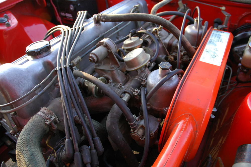
Apologies for jumping in here so late in the game, but I thought that the OE fuel hoses running from the fuel rail to the float bowls (and from the fuel pump to/from the fuel rail) were not fabric covered. For the three Z's that I've had my hands on (one '70 and two '72's), these hoses were not fabric-covered. Of course, hose originality can be tough to nail down because they've so often been replaced during the earlier service life of the car. Maybe others can comment... Have a look at this photo of an unrestored Jan. 1971 car.
-
Walter: Welcome to our 'self-help' group. Longtime member, Blue (now goes by '240260280', IIRC) has previously written a detailed article with dozens of photos, that explains the teardown and rebuild of the MasterVac unit. Use the search function to find it.
-
Joe: There are some excellent write-ups already on this site regarding complete tear-down of the steering rack, tie-rod end issues, substitute dust boots, etc. etc. I'm not going to find them for you (maybe someone else is feeling more energetic), but I encourage you to use the search function (select 'Topics').
-
I've just gone through this exercise, using a re-pop grommet from 240ZRubber. Their grommet fits well, relative to both the cable (ID) and the firewall hole (OD). However, there's no way that the grommet's ID could be stretched enough to fit over the cable's metal end fitting (same at both ends, BTW). And believe me, I tried. I had to slice the grommet and then use KrazeeGlue to bond the cut edges after I installed it over the cable. This particular grommet is made from a stiffer material than the original, so it was a struggle to make it fit into the firewall hole. In the process, my glue joint gave up. However, the cut edges aligned nicelly once the grommet seated into place and now you'd never know it was cut. I'm going to guess that MSA discovered the same challenge... and came up with a bad solution: a grommet that fits over the cable end fitting but won't fit into the firewall hole. I recommend you just buy the grommet from 240ZRubber and be done with it.