


Namerow
-
Posts
1,483 -
Joined
-
Last visited
-
Days Won
23
Content Type
Profiles
Knowledge Base
Zcar Wiki
Forums
Gallery
Events
Downloads
Store
Blogs
Collections
Classifieds
Everything posted by Namerow
-
Nope. The 'S' terminal becomes and stays 'live' over the full range of key travel in the 'Start' position. Same for both switches. I don't necessarily disagree that there might be something wrong with the internals of my Beck & Arnley switch, but the housing halves are staked closed so I'm not interested in try to get it apart to see what might be going on. Maybe somebody else has got an aftermarket 240 ignition switch lying around loose that they could try the same experiment with. Just to satisfy my curiosity.
-

Intake Manifold Thermostat - How do I check it and service it?
Namerow replied to Namerow's topic in Open Discussions
Hope it survives the heat from the exhaust headers! The orange paint on your air cleaner housing looks almost iridescent in the photo. Did you use a special paint, or is it just a trick of the lighting? -
Nope. Nothing's loose. The detent for the Start position (for either switch) isn't a 'click-stop' detent like the other positions. The Start detent actually provides 5 or so degrees of key travel before the key runs up against a hard stop. During that travel, the key rotation is resisted by an internal spring. It's something you probably wouldn't notice when you're doing a normal engine start, but you'll notice it right away if you try operating the key with the battery disconnected. It's probably there to provide a cushioned stop for the key when the operator is extra-energetic about trying to get the engine started.
-
Intake Manifold Thermostat - How do I check it and service it?
Namerow replied to Namerow's topic in Open Discussions
The thread for those balance tube ports is British Standard Pipe Thread. I assume that the threads on your vacuum gauge were NPT. Did you re-thread one to match the other, or was the NPT fitting close enough to just crank it into place? -
I have a question for the electrical experts: I bought a Beck Arnley aftermarket ignition switch to replace the 40-year-old OE switch in my '70 Z. Seemed like a good preventative maintenance step, with the steering column currently out of the car. However, I've found puzzling difference in the operating logic of the two switches. It has to do with the switches' 'R' circuit, which I'm pretty sure means, 'Resistor' (as in, ballast resistor for the coil/tach circuit). With input power applied to each switch module by way of the 'B' (battery) terminal and output monitored at the 'R' terminal, this is what I find: Key Position "R' - OE Switch 'R' - Aftermarket Switch OFF dead dead ACC dead dead ON dead dead START live live to start, then goes dead when key is turned further against the detent spring It's been noted elsewhere that the Z's ignition circuitry is designed so that the ballast resistor is bypassed during engine start (so as to deliver higher voltage to the coil/points) and then brought back into the circuit during 'run' operation (so as to operate the points/coil at the lower, normal voltage). So a 'live' condition at the 'R' terminal of the switch means 'resistor out', whereas a 'dead' condition equates to 'resistor in'. My OE ignition switch adheres to this simple, two-step 'resistor out/resistor in' logic. The aftermarket switch does too... at first. But then as I twist the key a little further in the 'START' sector, working against the resistance of the internal spring to take the key all the way to the hard stop, the switch action reverts to 'resistor out'. This would typically be where the key would sit while cranking the engine (i.e. twisted all the way up to the hard stop) I'm not certain whether the aftermarket switch was designed this way on purpose, or not. There's also the possibility that it's just a defective unit. So now I'm not sure whether I want to use it. Does anybody have an idea about why the aftermarket switch would change from 'resistor out' to 'resistor in' halfway through the 'Start' segment? Could it be that this was done on purpose, so that the duration of the high voltage ('resistor out') condition in the coil/points circuit would be restricted to just the first part-rotation of the crankshaft, so as to avoid burning the points during prolonged cranking?
-
I have a rebuild kit on order from MSA. When I get the chance to have a look at it, I'll let you know whether the two seals are identical vs. different.
-
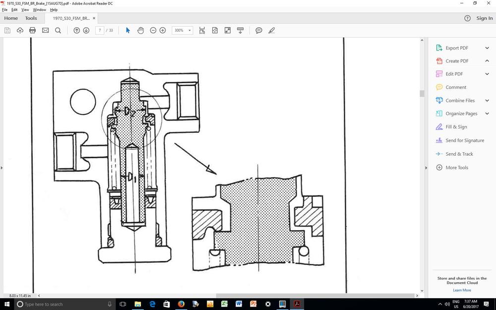
Good to hear... but I'd still like to know how a proportioning valve turned into a no-flow valve. The more I study the FSM (see below), the more it seems to me that the 'upper' seal is critical to the way the valve works. It appears to have a unique cross-sectional shape. Maybe you installed it upside down?
-
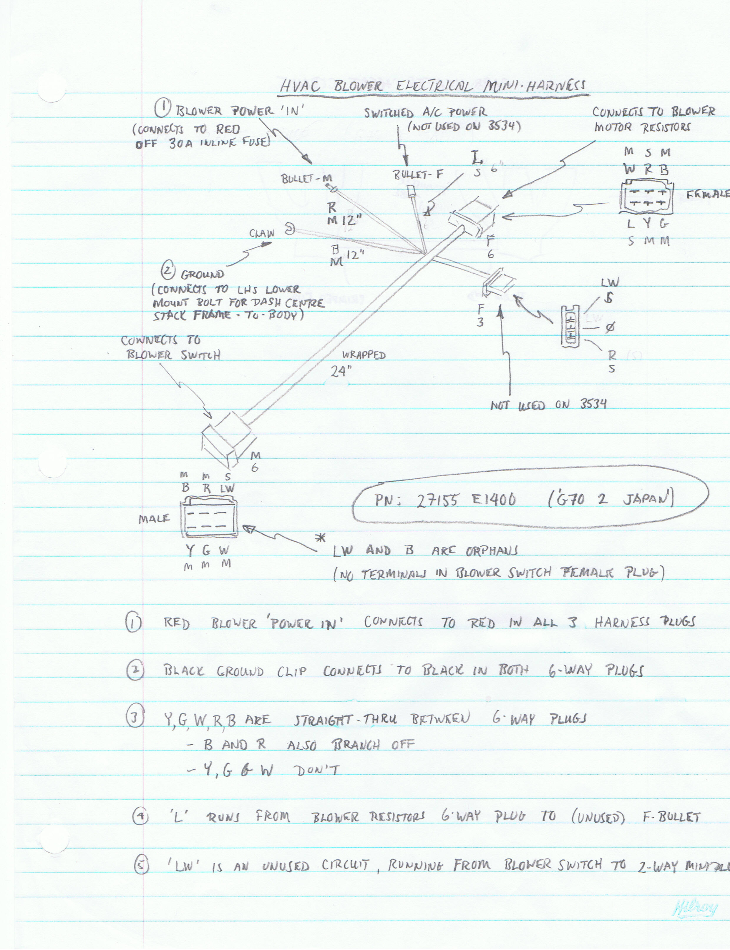
The elusive HVAC mini-harness is lurking in the bottom right corner of Fig. 1.2 in the FSM Supplement that CO has posted. It also appears in the bottom right corner of Figure VI-1 at the end of the FSM Supplement, complete with some labeling and a legend with some wire color coding to (sort of) tell you where some of its connections connect to. The blue wire is, according to the legend, there to provide a power signal to the A/C system... which was, of course, available only as a dealer-installed option, meaning that for many Z's the blue wire never ended up being connected to anything over the life of the car. When it came from the factory, the blue wire ended in a female 'bullet' connector. I've scanned the notes I made for the HVAC mini-harness and they appear below... (note: everything you see in my notes is specific to a 1970 Z with manual trans):

.thumb.jpg.65ad2d812299c8f3b47c81ea70cad6f1.jpg)
-
Thanks, Mark. Based on your comments, I tried the vice-and-socket routine again and this time I was able to get one of the cups free -- from the shaft-side yoke. But that was it, so out came the cut-off wheel (fortunately, the spider had shifted far enough to one aside to let me get the cut-off disc into the gap without damaging the inner face of the yoke). After using the cut-off wheel, I was able to separate the shaft from the splined yoke, which made subsequent work a bit easier. I had to cut both legs off the spider to get it out of the splined yoke. Even after I'd extracted the remains, there still was one cup that refused to budge more than about 1/32" in either direction. Sixty seconds with a MAP torch got the yoke hot enough so I could tap out the cup with a punch. Additional comments for anyone else trying this: For each of the two yokes, I found that one of the two cups would not move inward (and, yes, all the retaining clips had been removed). That meant that my press-out efforts with the vise and sockets would only work in one direction. Even in the successful direction, there was a loud 'crack' before the cups started to move. Instead of using an oversize socket on the exit side of each yoke, I ended up grabbing some 1x2 hardwood scrap and drilling a hole in it (11/16" drill, if you do this). Thew wood piece could then be propped up inside the vise jaws to the right height and then sit there without needing a hand to hold it in position. It was then much easier to juggle the combination of the other socket, the steering shaft and the vise handle while trying to get everything aligned and the vise jaws tightened down enough to hold everything in place. I think I'm going deep-freeze the new spiders and cups and then use a torch to get some heat into the yokes before I try re-assembly with my new Kawasaki U-joint kit. The cups look like they'll be really easy to get cocked a bit sideways at the start and I don't want to risk chewing up the bores.
-
I'm digging up an old post, but the topic is a current one for me and I know that Z-Cars probably isn't too far away... Jim: You said that the spider for the steering shaft U-joint can't be removed by a straight press-out, but you made this comment in reference to the later, staked-type U-joint. In an earlier post in this same topic, though, you'd said that you'd replaced one of the earlier-design, circlip-type U-joints and commented on what an easy job it was. Well, my 70 Z's steering shaft has the circlip-type U-joint and I'm having the interference problem that you mentioned in reference to the staked-type U-joint. My question: Were you really able to press out the spider on the circlip-type U-joint, or did you have to cut that one out too?
-
I may be difficult to replicate one of these tags to OE standards... The plate itself is made from stamped-out piece of aluminum sheet The black top coat has a satin-ish semi-gloss appearance, with a barely noticable top-to-bottom 'grain' The 'HLS30' characters were produced by leaving the shiny top surface of the aluminum plate stock exposed. The characters have no 'lip' around their edges (i.e. the entire top surface feels smooth), so the black overcoat must be just mil's thick. Masking and painting won't replicate this. I think the overall process used originally would have consisted of some kind of silkscreening. Maybe somebody else with experience in a print or photography shop knows better. The five (or six) digit VIN numerals were produced by the die punch cutting through the black top surface of the plate and penetrating into the underlying aluminum. There doesn't appear to have been any paint used to highlight the 'trench'. Once again, what you see is the exposed aluminum of the underlying plate stock. You'll need to find a metric number punch set with the correct font style (?) and the correct size (seems to be 7mm x 4mm). It sounds to me like Mike at Banzai has priced this out quite fairly at $450 (to do it right). If that's too steep for your budget, maybe you could just use the VIN tag that Grannyknot has sent you. Given the car's salvage-title history, it would seem to be mainly just for show (although your local constabulary may not share this view). The VIN that's stamped into the firewall is the definitive identifier of the vehicle and it should be backed up by the number stamped into the plate in the engine bay.
-
Silly question, but it needs to be asked: Is there any chance that you plumbed the valve back into the system backwards?
-
Suggestion: Buy some plastic rod (black, if you can find it) of the appropriate outside diameter. Cut an appropriate length, with an inch or so extra that can be chucked in a drill press (preferred) or an electric hand drill. File a rounded contour onto one end. Then drill out the core to suit the diameter of the lever rod on the seat. Cut of the end that was chucked in the drill/drill press. Spray paint with satin black, with particular attention to the two end surface. When the paint had dried adequately, epoxy it in place on the seat lever rod. Cut a length of heat shrink tube and apply over the flat length of the nylon piece. Heat to shape. Done. The original piece isn't exactly soft to the touch, so you won't be giving up much in feel by using the hard nylon and shrink-tube covering. The original piece has a bit of a taper to it, but no one will notice that your 'faux' cover is straight.
-
Nice looking car, DJ. Seems bargain-priced at $20K . I know it's subjective, but -- for me -- this is one of the few exterior/interior color combos I've seen where the blue interior trim seems to work well. GLWTS.
-
It's a form of 'acoustic duct lining' and it's there as an airflow silencer. Not sure how effective the end result is. You'd need to try a the system 'with' and 'without' to decide. BTW, I did this same job myself a couple of years ago. It's very time-consuming. There are a lot of foam gaskets in the Z's heater/blower/vent/duct system and some have very tricky shapes (esp. the piece in your photo). Many need have holes punched out for joint fasteners. Rather than use contact cement to try to glue new foam in place (messy), try making your own adhesive-backed foam by bonding the foam to two-side-adhesive-backed clear vinyl sheet (8-1/2" x 11" -- available at craft stores). Leave the peel-off paper in place on one side of the vinyl sheet. Now draw your gasket templates onto a piece of 8-1/2" x 11" printer paper and use a glue stick (stationery supply store) to glue the paper to the vinyl backing sheet. Now you can use a razor knife, scissors, hole punches, etc. to cut out your gaskets. When done, peel off the backing sheet from the vinyl-backed foam and stick in place. Most of the gaskets should be about 1/16" thick, installed. I used 1/8" open-cell foam (compresses down to 1/16"), but I think some craft stores sell adhesive-backed, closed-cell neoprene sheet in 1/16" thickness that might be an equally good . Don't use the 1/4"-thick adhesive-backed foam 'tape' that hardware stores sell for home weatherstripping. It's too thick and the end results I've seen in photos look pretty marginal. The foam covers for the two big 'flapper' doors need to be top-faced with thin, upholstery-type vinyl. If you don't do this, the foam will wear off quickly around the perimeter, where it seats on the ridge in the housing. The gasket that's the most difficult to get right is the one around the perimeter of the heater plenum, where the removable end plate installs (for access to the heater matrix).
-
OK, I'll bite. How does the same car get listed from two different locations at the same time? (not to mention, at wildly different prices)
-
Lots of speculation over why these shades were used. No definitive explanation that I'm aware of.
-
From bench testing, I found that the impellers from my 70 Z (impeller made of metal) and my old 72 Z (impeller made of plastic) weren't terribly sensitive to which direction they were rotating in. When I inspected the impeller from the Honda Civic blower that I had bought mostly for its more modern motor, I discovered that its blades were oriented in the opposite direction to the Z impellers. I also discovered that the Honda impeller was very direction-sensitive and -- when turning in its preferred direction -- was both more powerful and quieter than the Z impeller. My conclusion: The Z impellers aren't a particularly good design. Recommend you try both your TYC and original impellers in the Z blower casing, just like I did. That will let you choose which one you like best (for output and noise) and will also tell you the direction in which it needs to rotate to produce best results.
-
From my experiences with resurfacing the dash for my '70 Z: The black vinyl skin will tear, not 'peel', off the underlying foam. There'll be a lot of craters and voids generated in the foam and that will add to the challenge of getting the final shape of the new-foam substrate the right size and shape. Arguably better to grind the vinyl off than to try to pull it off. Wear a dust mask! The contour sanding of the top and front finished surfaces is very difficult to get right. Same goes for the gauge pod recesses. For what you're suggesting, the challenge will be not just to restore the contours but also the overall dimensions (i.e. You'll be trying to build back the correct shape in 3D space relative to the sheet metal armature). I hope I never have to do this particular job again. From what I've seen, 'Just Dashes' do great work. They, too, have to shape and contour the Z dash's very complicated 3D shape in (new) foam before they vacuum-form the vinyl top layer in place. Lots of hand labor, so US$1500 seems reasonable. Unfortunately, that's just the base cost. There's also crating and 2-way shipping, shipping insurance, and sales tax. Probably Cdn $2500 - $3000 for us poor Canucks when all is said and done. Not saying your idea won't work, Blue, and I like it in concept. However, there will be lots of challenges along the way. If you've got a cap and a spare dash to use as a sacrificial victim, I'm sure we'd all like to see how you make out.
-
Interesting. I have on from my 70 Z with exactly the same granulated surface deterioration of the slotted black plastic 'grommet'. I was going to try to replace it, but now I can see that it's actually 'patina'. So that means my selling price just went up by 100%. Bids?
-
Thinking about installing an BMW M6 engine in my Z
Namerow replied to grannyknot's topic in Build Threads
Re your leather gloss issue for the door panel material, why not just try a coat of paste wax (or, if it makes you feel better, clear shoe polish)? Alternatively, check to see whether SEM (or a competitor) offers a satin finish clear for use with vinyl and leather. Suggest you have a look at 'Parasol' (Toronto). They will custom-mix and ship to your door. I had very good results with their products. -
Listed by ZCar Depot @ $119.00... https://zcardepot.com/engine/cooling-heating/coolant-line-bypass-pipe-crossover.html?limit=128
-
Are the contact points in the Z's switchgear actually made from silver?
-
Thinking about installing an BMW M6 engine in my Z
Namerow replied to grannyknot's topic in Build Threads
Where have the mice been living while you've been remodeling their home? -
I haven't tried to do this myself (yet), but your picture gave me an idea... Try using two loops of fine-diameter fishing leader line (plastic) to tie and knot the spring into compression. Position your loops at the 12 and 6 o'clock position of the spring circumference. Drop the seal, the valve and the spring into place. The two loose ends from each loop of line will stick out of the bore. Insert the circlip, with the loose ends of lines going through the centre. Once the circlip is clicked in place, use an X-acto blade to cut the loops of line and then use tweezers to pull the remains out of the bore. It might work.

.jpg.ea68db7982521082c66f98df5f3b9454.jpg)