


Namerow
Free Member
-
Joined
-
Last visited
Everything posted by Namerow
-
 Based on Jeff's experiences, it sounds like the ambient air temp in the engine compartment is irrelevant and the real culprit is engine heat conducted through the metal fuel rail mounts. I wonder if the solution might be as simple as thermally isolating the rail mounting points from the engine by using rubber standoffs? (I'm thinking grommets in the range of 1/4" to 1/2"-thick). This would seem pretty easy for JAlex to try and probably 100% reversible if it doesn't work out.
 -
I hired the services of a local specialist. Their only business is extracting snapped off fasteners. Primary clientele are dealer service departments. Apparently, there are chronic, high-dollar fastener failures on certain premium vehicles to support this kind of trade. The tech showed up at my home with a roll-in cabinet filled with specialty tools. Job was done in 15 minutes. Cost: about $150. For me, that was money well spent, as it allowed me to move on to more rewarding steps in my restoration project.
-
This car was a great build. I would go with Bring a Trailer first, with a reserve set at $30K (nothing ventured, nothing gained). If you have no luck there, you'll be stuck with eBay. FWIW, I don't think that this is the right kind of vehicle for the big-name winter auctions in Arizona. GLWTS.
-
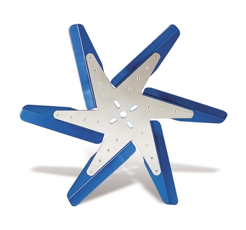
Don't overlook the possibility that the 'reverse-rotation' fan may be just a flipped photo image. Does this look better?... What's your goal in changing to this style of fan? More CFM? Less noise? Weight reduction? Hi-tech look?
-
Fine looking lathe in the background there, Jim. Details?
-
OK, I may have found the answer myself. Eric Neyerlin's excellent ZParts.com site includes a pair of photos that document three different shapes of S30 choke knobs, as well as variations of 'with script' and 'without script' (irrespective of shape). It looks like my 'mystery' items are actually one of the two different 'shape' versions that were used for the 72-73 Z's. Probably from the early part of the 1972 run, since their shape is kind of 'in between'. If you're interested in more details, go to the ZParts.com site and click on the tab at the top marked, 'ZP TECH'. Then look for the link, "S30 Parts Comparison Index". Then search on 'choke knob'. Eric's notes also document the use of at least three different types of set screws for the S30 choke lever. This would make a great display collection for the 'driven' 240Z/260Z enthusiast: a complete set of all the different choke (and hand throttle) knobs used between 1970 and 1974!
-
As near as I can understand it, the conventional wisdom is that there are only two versions of the choke knob for the 240Z: an early, rounded version and a later, more square-ish version (the knob in the 260Z had a more slender design than either of the 240's, and I guess the fuel-injected 280Z didn't have a choke knob at all). In all of the many pictures that I've seen of the 240 choke knob, never does the design include the script, 'CHOKE' in addition to the icon. My small assortment of choke knobs (see photo) includes these three items: right - a new, later-style knob left - two used-condition knobs of an unknown origin, both of which include both script and icon. The two mystery items are slightly asymmetric in design, but not to the same extent as the no-script 'round' and. They each came with identical slot-head set screws that fit nicely into the recess on the leg. The thread diameter measures as 3.0mm. However, I don't know whether they actually belong to the mystery knobs or not. One final note: The mystery knobs fit well on the metal S30 choke lever in two respects: 1) the slot for the lever is the correct width and depth, and; 2) the set-screw hole in the plastic knob lines up with the set-screw hole in the metal lever. In a third respect, the fit of the mystery knob is off a bit: without the set screw in place, they rock a little, fore-aft, when fitted onto the lever. So: Does anyone know where these two knobs come from? They match the known S30 knobs' graphic quite well and the set-screw location is spot-on. In shape, they seem to be halfway between the 'early' and 'later' S30 designs. Maybe they came from a Datsun Roadster or a truck?

-
hmmm... My car's VIN is 5/70 and the tab that came unsoldered was the lower pssgr side. I think that what we have here may be a process or material problem, rather than a worker problem. Fortunately, the fix is easy. And on the 'glass half-full' side of the equation, I can't think of too many other places on the 240Z where things just 'broke'.
-
For our American Z-car friends, you have no idea how much more expensive it is to have a 'car habit' when you live outside of the USA. We never get access to those 'free shipping' specials that those of you who live inside the USA enjoy and we get absolutely killed by FedEx and UPS brokerage fees when parts come across the border. Add to this customs duties and local sales taxes and -- here in Canada, anyway -- you can pretty much take any advertised price for a part from a USA vendor and add over 50% to figure out what the delivered cost will be. As an example, the premium that I paid over vendor's list price for a set of Wesco seat belts was 68%. And then there's the currency exchange. But that's another story.
-
That's the accepted way of stopping crack growth. Because you're going to have the crack welded, though, doing this might be either: a. even more important (large thermal stressing), or; b. not necessary (welding solves the issue). You won't know the correct answer until after the heat hits it. Because of the fear that the correct answer may be 'a', a compromise solution might be to drill a hole to half depth. Looks like a 3/16" bit would be about right. If your welder buddy has a lot of experience with aluminum casting repairs, he should be able to offer a better opinion.
-
NAPA
-
Some time ago, Blue posted a nicely-illustrated piece on rebuilding a MasterVac unit. However, I think it was on the Atlantic Z Club site (nla?). Maybe he can re-post it hear. IIRC, his problem was a ruptured diaphragm... which he repaired using some kind of sealant. As for me, I decided to just buy a rebuilt unit from NAPA. It wasn't that expensive and it spared me the grief of taking the old unit apart.
-
I think that the compliancy of the Great Stuff foam may actually be a plus rather than a minus. After 40+ years, the original foam has about zero compliancy left, so the stuff that goes in to fill the cracks has to be able to give as the dash surface grows and shrinks with radiant heat and changes in interior temperature. For my repaired dash, my biggest fear is that the top, skim coat of 'Bumper Bite' repair compound won't have the same degree of compliancy as the foam underneath it. The top coat is only bonded to the original vinyl skin by the width of that skin, and if the bond fails, a crack will emerge. I beveled the OE vinyl skin so as to increase the width of the bond line, but that still only makes the bond along each seam about 3mm in width. Only time and sunlight and temperature will tell the tale. Since I completed the repair, my dash has been stored in the basement for 2 years, waiting to be re-installed in the car.
-
Here's a link to an article in EngineBuilder.com that provides some great insights into the difference between the fuels that are sold today vs. those which were the standard back in the day when the original Z's were designed and used... http://www.enginebuildermag.com/2013/11/impact-of-todays-fuels-n-carbureted-engines/ Among other things, there are some interesting points raised about fuel volatility and ethanol drop-out and the implications these fuel characteristics have for long-term (or even shorter-term) storage of vehicles with vented fuel systems. The EngineBuilder.com site looks like a great resource for owners who like to pursue performance improvements for their stock engines.
-
I successfully rebuilt the Harada antenna from from my 5/70 Z about a year ago, using Mr. Purcell's excellent write-up as a guide. My antenna does have the bullet tip. In addition, the motor housing 'can' does not have a model number stamping. Instead, it wears an embossed, circular mftr's plate (same as Purcell's, IIRC). Maybe we have an 'antenna expert' in this club who knows if/when Nissan switched to an updated Harada antenna (which I assume yours to be). I don't know whether your unit has had a non-Harada mast substituted or not. I kind of doubt it, because I think it would be a difficult swap (the nylon drive 'rope' is attached to the base of the center section of the mast in a fairly permanent way, IIRC). On the other hand, maybe these things all used a generic mast design, regardless of mftr. I can tell you that the disassembly/re-assembly of the clutch is pretty straightforward and there's nothing spring-loaded that's going to explode out of the casing. The main thing to observe during disassembly is how the (black) plastic 'guideshoe' pieces for the nylon 'rope' fit into the casing. I've got lots of pictures stored away if you get lost. BTW, as you explore the innards, you'll find out why the outer casing rusts. There's a rather poorly designed drain in one of those guideshoes that's supposed to give an exit path for water that weeps down the chrome mast. It probably clogged after about Month 3 of use in most Z's.
-
BTW, when I just made the post above, an advert placement appeared in the middle. I have no idea how that happened. New feature for posts?
-
Here's are links to a couple of good introductions to things that may need attending to in a Z... http://datsunzgarage.com/probs/index.htm http://www.zparts.com/zptech.html Keep in mind, though, that comprehensive list of things to watch out for might run to several pages in length . The CZCC website has some great articles posted by members on recommended repair and upgrade strategies, as well as sources for OE and upgraded parts. The 'Search' tool is your friend. If the floor of your fuse block has melted (and there's a fair chance that it has), it is possible to do a repair. A better solution, though, might be to buy a replacement or an upgraded unit. Motorsport Auto ('MSA') can help you out with this. They also supply upgraded headlight and park/turn wiring harnesses (as do a few other vendors, including the one you for which posted the link).
-
I know, I know. Last batch goes in the tank tomorrow, so I plan to take a run up north on Sunday to return it. You seemed to be having so much fun with your MegaSquirt adventure that I thought you wouldn't notice the bare spot on your storage shelf. Note that my regular email isn't working right now, so this site is the best way to get in touch with me for the time being. BTW, you're probably going to need to order a bottle of blue chromate and a bottle of brightener from Caswell to get the look you're after. I've got a bit of the blue chromate left over, but it won't make a bath big enough to cope with anything other than quite small parts (see Patcon's comments from earlier today -- too dilute a mix doesn't get the job done). As for using sugar as a brightener in your electrolyte, I'd say, 'caveat emptor'. From reading I did earlier this year, I learned that some sugar-based brighteners make a mess of your bath and might even poison it. Only glucose-type sugars were said to work, and a specific type of corn syrup (high-glucose) was recommended. I tried that in my vinegar/Epsom salts solution and it didn't seem to do much. In fact, it was right around that point when I started to experience terminal plating problems with the set-up. Don't know if the corn syrup was the culprit or not. I was also suspicious of contamination on my wire wheel. That's the problem with this process -- when things go wrong, it's really difficult to figure out why. Too many variables. If you run into trouble, the only safe option is to clean or replace everything and start all over again.
-
Both Grannyknot and I have tried this 'poor man's' strategy. Actually, I tried it a few times and have a cellar littered with empty vinegar bottles to prove it. I won't try to speak for Grannyknot, but I can say on my own behalf that (despite best efforts re parts cleaning and prep) I wasn't satisfied with the results and finally decided to cough up the $$ for the Caswell chemicals -- along with borrowing Grannyknot's adjustable power supply. Although the vinegar/Epsom salts/fixed-output power supply strategy didn't cost me much money, it did cost me a lot of wasted time and effort. I now wish I'd gone the Caswell route in the first place.
-
The only time I've seen parts come out 'brown' from the electrolyte bath was when I when I realized that flash rust had set up before they went in. Zinc is grey. I'm not sure how it can become brown. Depending on how good a job I did at cleaning the parts and setting the amps and adding the brightener, my parts come out of the electrolyte anywhere from dull grey (adequate job) to shiny grey (great job) to grey-black-with-black-flakes-attached (crappy job). Re chromates & pH levels: I'm not a chemist, but it's my sense that neither of the chromates works by way of acidity. The brightening effect that I've observed (in my admittedly brief experience with all of this) was achieved by virtue of the Caswell 'brightener' liquid that I added to electrolyte before I started a new plating cycle. It really does make a difference. More so, I think, than polishing the actual part before starting to plate. In fact, I didn't even use the wire wheel on the last couple of parts that I plated (they were just glass-bead-blasted) and they seemed to come out pretty good. The Caswell brightener is supposed to 'brighten' by way of making the zinc deposit/plate out on the part's surface in a smaller particle size. I'm not sure how a dip in nitric acid after plating would brighten a dull zinc surface. But -- again -- I'm not a chemist. Maybe someone else can chime in here. While I prefer logic and science, there seems to be a dose of witchcraft (or maybe 'which-craft' would be more accurate?) involved in DIY plating.
-
That's a little worrisome, considering the cost of the original job and the potential damage that could result from an in-service failure. Hope he's paying for the return shipping costs, if not refunding you for at least part of the original charge.
-
My #1 caution (as others have said before me): Your parts need to surgically clean. All of the cleaning steps -- blasting/tumbling, acetone or MEK solvent wash, hot detergent wash, acid pickle, and distilled water rinses between each of these cleaning steps -- should be considered mandatory. Wear nitrile gloves to keep finger oils of the parts. Clean the nitrile gloves with alcohol before you touch anything. Re-clean them or replace them regularly. If you stop to scratch an itch or have a snack, clean the gloves afterwards. Clean all of your bath containers with alcohol before you add the fluids. Filter the Caswell electrolyte bath through a clean/new metal coffee filter before you use it. Use a fresh wire or fibre wheel on your grinder/buffer (or Dremel) and keep it away from any oily parts. A contaminated wire wheel will 'burnish' the oil contamination into your part, making it necessary to go all the way back to the blasting cabinet or tumbler. You'll never trust that wire wheel again, either. Install your hanger wire(s) on each part right after the mechanical cleaning steps have been completed. Better to make the hanger wire too long than too short. Extra length lets you adjust on the fly so that the part sits at the right depth in the electrolyte bath. For parts with complicated shapes or partly-'shaded' surfaces, install two hanger wires in different places so that you can quickly/easily change the part's orientation relative to the anode(s) when you're half-way thru the plating cycle. With all of this semi-religious cleaning, your parts are really vulnerable to flash rusting in between steps. For that reason, keep them immersed in a distilled water bath between cleaning steps. Don't let them sit in the water for very long, either. Flash rust is your #2 enemy in electroplating. Consider heating of the electrolyte bath to be mandatory. Keep it in the 100 - 110 degree F range. I rigged up a hot-water-tank heating element to do this. I heat the bath to 110 degrees before I start each 20-minute plating cycle and then I remove the heater. The temp never drops under 100 degrees during the 20-minute plating cycle. Clean the heating element with alcohol before you drop it into your $200 electrolyte bath. Consider a bubbler in the electrolyte bath to be mandatory (a cheap one from the Pet Supply store works fine). Clean the plastic tube with alcohol before you drop it into your $200 electrolyte bath. Consider heating of the detergent bath to also be mandatory. I bought a cheap crock pot. It works fine. Put the crock pot liner with the detergent mixture in the microwave for about 10 minutes to get it up to temp. The crock pot element will handle it from there. I haven't bothered with heating for the acid dip or for the chromate dips. I'm not convinced it makes a difference (and Caswell doesn't recommend it for the chromates). Add a 1/2 tsp of the Caswell brightener to the electrolyte bath every time you put a new part, or group of parts, in for a new plating cycle. The brightener really does make a difference. Just don't over-do it. It might be just me, but I've had poor luck trying to do multiple parts in one plating cycle. Might be ok for nuts and small bolts, but I don't recommend you try it on anything else. This adds a lot of time to the overall process. However, every screwed up part adds even more time to the process. I figure it makes more sense to devote the extra time towards making the part come out right on the first plating attempt, rather than spending the same time re-doing the entire process on several parts just because you wanted to speed things up. This electroplating process just punishes mistakes. If a part is hollow (e.g. the infamous Inspection Light housing), the surface area that you use to calculate your amps should be the sum of the external surface areas only. If you add in the internal surface areas, your amps will be too high and you'll 'burn' the part. The surface area of the edges of stamped-metal parts need to be included in your area calculations. Most of the Z's little parts are 1 to 3mm in plate thickness. You'd be surprised how much the edges contribute to the total surface area of each part. The iridescent 'yellow-green' result can only be achieved if you pre-dip in blue chromate. The iridescent 'yellow-green' appearance doesn't really show up when you remove the part from the yellow chromate bath. It seems to really start to 'pop' after you rinse the part with water and then apply heat with a hair dryer. Maybe just my imagination, but that's what I saw happening. I'm not sure whether you've purchased a controllable-current power supply or not. If what you've got won't let you control current, you can easily rig up a daisy-chain of park/turn-signal bulbs. You can patch into the daisy chain at various points until you get the current that you're after. Not as quick and elegant as turning a control knob, but a lot cheaper. BTW, Radio Shack-type potentiometers won't work. Even modest levels of amps burn them up. Hope this helps. Looking forward to seeing pix of your results.
-
I did complete a second round of plating last weekend. Things turned out well -- which was a relief, because my first session had run into trouble -- some kind of surface contamination on the last few parts I tried (might have been residual WD-40 that I'd used to keep the parts from rusting while were sitting around). Before starting the 2nd session, I refreshed all of my distilled water baths, made a fresh batch of acid, double-strained the electrolyte (you never know), and made fresh batches of detergent bath and yellow chromate dip. I cleaned the inside of all of the bath containers with alcohol, too. The problem parts went back into the blasting cabinet before the cleaning and plating was re-attempted. I was not able to refresh the blue chromate dip because Caswell only gives you enough base material to make a single batch (unlike the yellow chromate, where they give you enough to make several baths ). I think that the renewed blasting was what actually saved the day... but I wasn't going to take any chances with the baths. Although I've certainly thought about it, I have not yet picked up a pH meter. If I can find one at a plant nursery tomorrow that doesn't cost an arm and a leg, I'll be happy to try to help you out. FWIW, my blue chromate dip was mixed according to the instructions on the side of the Caswell bottle and it never seemed to produce as deep a blue tint as your photos suggest you've been getting with yours. Following the instructions, I ended up with about 1/3 of the bottle's contents unused. Maybe you used the whole bottle? My point is that my blue chromate dip has produced pretty good results (to my eye, anyway), both on its own and as a pre-dip prior to the yellow chromate bath. Maybe you should test yours on a single part in its now 'diluted' form to see if it might still produce an acceptable result? BTW, I actually like the results produced by the blue chromate dip about as well as I like the yellow iridescent look produced by the combined blue/yellow dips. I'll post some more pictures and comments this weekend. I also made a chart of surface areas and start-off amperage settings for each of the parts that I've plated. I'll try to post that, too. Might save Blue and others a lot of measuring and calculating time.
-
I took my Z's hard plastic panels from black to butterscotch using a vinyl 'die' produced by a Toronto-based supplier called Parasol. They custom-matched the colour based on a sample from the seat covers that I bought from Banzai Motorsports. Very happy with the results in terms of application, coverage, colour match and final appearance. Cost was about $130 Cdn for a quart. Applied with an HVLP gun. I used the same product on the soft vinyl trim, too. More difficult to get uniform coverage than for the hard plastic pieces (maybe because of 30+ years of over-zealous Armor-All applications on soft vinyl by PO's in an effort to keep them 'soft'). Still, I'm pretty happy with the results. Bottom line is that you can re-colour a Z's interior panels successfully using SEM or other similar products if you read and follow the directions. Only exceptions are the seats, where I wouldn't be confident about either coverage or longevity. The vinyl die mftrs might choose to differ, though. There are companies that seem to be making a make a good business out of re-colouring boat interiors (including seats) using the same stuff.
-
Yup. That's what my home-made version looks like, too! Probably won't take you more than three attempts and 30 minutes to make one from scratch. In the 'open' position that Mike's picture shows, the spring still needs to have a bit of tension in it (to keep the lid forced open). That should give you an idea of what the spring should look like when it's fully relaxed/extended -- i.e. the two legs will sit at about the 12 o'clock and 8 o'clock positions.

