


Namerow
Community Member
-
Joined
-
Last visited
Everything posted by Namerow
-
-
Sorry. I'm out.
-
No. There is no quick fix. Buy a dash cap (molded and textured black ABS plastic shell). Use the 'Search' function on this website to do some studying about dash caps. There is extensive discussion available, along with lots of great photos and advice.
-
You can forget about PB Blaster (or any other 'penetrating' oil) having any useful effect in getting stubborn exhaust manifold fasteners loose -- even if you add a bit more every day for two weeks. What you'll probably need is heat. Not just any heat, either. You need to get the fastener just close to glowing. I've read that an oxy-acetylene torch provides the best flame for this purpose. However, I've never had access to a gas welding kit, so I use a special torch head (provides an air bleed-in just downstream of the tip) on a regular propane cylinder to get the flame temp up. A regular (plumber-type) propane torch set-up won't get the job done. Even with this kind of heat, you'll probably only succeed at breaking the threads free. Let things cool a bit and add some oil to the threads before you do any more wrenching. You'll need to coax the fastener out. Loosen two increments, re-tighten one increment. Repeat until the fastener either starts to turn freely (good luck) or is fully out, adding a bit more heat and a bit more oil from time to time. Do not give in to the temptation of trying a power impact wrench. I -- like you and many other Z owners -- have had to deal with a snapped-off rear exhaust manifold stud. Mine snapped off about 1/16" below the surface of the head. I started a thread on this about six months ago and got lots of helpful input. However, there are no 'silver bullet' solutions. I you're handy with a MIG welder, that may offer the best solution. Fill the cavity on top of the stud with weld and then -- using a flat washer as a spacer -- weld a nut on top of the stud. The combination of heat shock and restored leverage gets the job done. Drilling the core of the stud out for follow-up with an ez-out is usually the road to hell (although some claim that using a left-hand drill bit works wonders). I would only let a competent machine shop try this -- and that means taking the head off. I certainly wouldn't try it with the engine in the car (limited access, no arm support, tiny stud diameter, engine mounted on an angle -- 'What could go wrong?'). The 'perfect world' solution is to have the stud material vaporized using an electric induction process. However, this isn't something a hobbyist can do and you may have difficulty finding a shop that has the equipment (unless you live in/near a major urban centre). Once again, the head will have to come off the engine. I believe that one of this site's senior members did a write-up (some time ago) about getting the air injection pipes loose from the exhaust manifold. Use the 'Search' tool to locate.
-
I suggest that you either get used to the crack or buy a full-coverage, glue-in-place dash cap. Otherwise you're in for either: 1) a long wait and an expensive-but-perfect fix from 'Just Dashes' (Van Nuys, California), or; 2) a long wait and a challenging, risky, D-I-Y fix by a local shop or you. Both options require taking the dash out of the car. Based on your adventures to date with getting your car fixed, I'd say that Option 2 isn't something you should attempt.
-
I`m beginning to wonder whether the US Northwest has replaced LA and Phoenix as the place to look for restorable classics.
-
I'm going to take a day off from my garage activities and come up from Burlington (Ontario) for the Saturday events. Hope to meet the CZCC 'cast of character's while I'm there drooling over the 90+ point S30's on display. I believe that Grannyknot will also be there on Saturday (looking for tips on how to program an ECU for a BMW M3 engine ).
-
I have a similar issue with my Harada. I think that Siteunseen's solution looks best -- buy a cheap replacement antenna and hope that you can steal the needed part for use on the antenna that's in your car. You risk only $19. Let us know if it works!
-
I'm afraid you're going to find some % of ethanol in just about every brand and grade of pump gas sold here in Ontario. For example, the Petro-Canada (owned by Suncor / Sunoco / Sun Oil) website has this to say: "Due to the fact that various fuel grades are blended at the point of sale, most grades of Petro-Canada fuel may now contain up to 10% ethanol. This represents a change from the previous state, where premium fuel was ethanol-free at Petro-Canada." In fact, they make a big deal about the use of ethanol in their 'Ultra 94' extra-premium gas, noting that its cool-burn characteristic is a key contributor to the high-octane number. The other big gas retail chains here in Ontario are Shell, Esso ('S-O' = Standard Oil = Exxon-Mobil), and Canadian Tire (who just sell somebody else's gas under their own retail banner). BTW, pump gas here is typically sold as either 87-octane (regular) or 91-octane (premium). Prices in the Toronto area right now are around Cdn $1.00 per litre, which works out to about US $2.85 per US gallon (1 US gallon = 3.8 litres). Chris is quite right about banks being the best place to get a decent exchange rate on your US cash. And they won't scowl at you when you ask. However, because you'll be a non-accountholder, they may want to limit the transaction to US$200. Anywhere else, you're probably going to pay a premium of between 5% - 15%. An alternative is to just draw Canadian cash from a bank's ATM, using your own bank card. Just check the machine and your card beforehand to make sure they're compatible (e.g. 'Cirrus', etc). IIRC, you'll end up paying a slightly premium rate ( +2%, say) and your own bank will ding you for a per-transaction fee of about $3.00. So, slightly worse than an over-the-counter transaction, but very convenient. This is the way I keep myself in local cash when I'm traveling in Europe -- usually ~ $300 at a go.
-
-
-
Don't forget to check the 'miscellaneous automotive parts' display rack at your local Canadian Tire store. I'm pretty sure you'll find at least a couple of types nylon headlight adjuster sockets, and one of them might adaptable.
-
I didn't know there were any fish left in Lake Erie! BTW, if you'd like to read some great stories about the trials and tribulations of life as an independent commercial fishermen (or 'fisher', as the CBC likes to call them), find a copy of ''Song of the Sirens" by Ernest Gann. Congrats on your retirement.
-
My ashtray suffered from exactly the same problem (design flaw). I rebuilt it and the results came out quite well. If you're unable to find a replacement unit and you're interested in giving it a try, let me know and I'll post some pictures of the rebuild.
-
Ashtray lid and Heater control knobs available at http://www.240zrubberparts.com .
-
Looking forward to your latest notes. I'm still not getting the results I'd like.
-
Watchmaker, no.... although there were a lot of slot cars and Revell and AMT model kits back in my youth -- many of which featured poor attempts at highlighting the trim with silver paint and a 000 paint brush. I always wondered how this foil applique stuff worked, so I decided to give it a try. The trick to success is to drink the beer after -- rather than before or during -- the job . Wish I could get my zinc plating efforts to work out this well! BTW, the foil is stuck to the plastic pretty solidly and shows no signs of lifting or even being prone to lifting. It has about the same 'stick' quotient as aluminum HVAC tape (i.e. pretty good). Nevertheless, certain adhesives don't handle high heat, so we shall see. The piece that's of greatest concern is the console insert plate, because it's located in a 'busy' part of the interior and the foil lines are thin. I have no experience with Sharkhide, so not sure whether it would help or not. For absolute protection, a coat of epoxy matte clear would seem to be the right way to go.
-
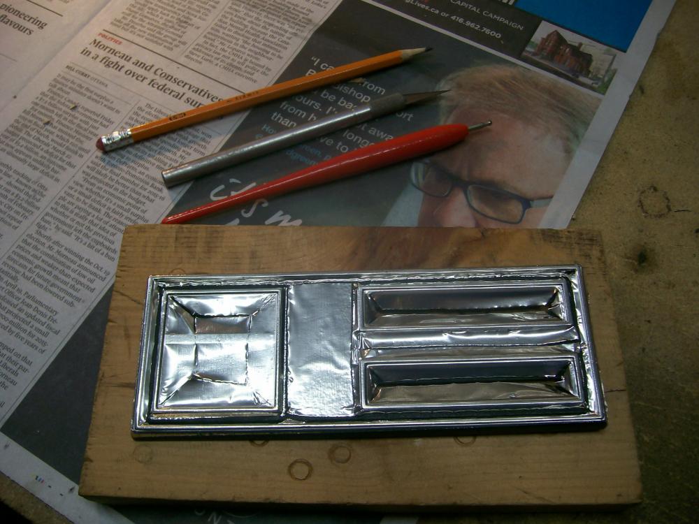
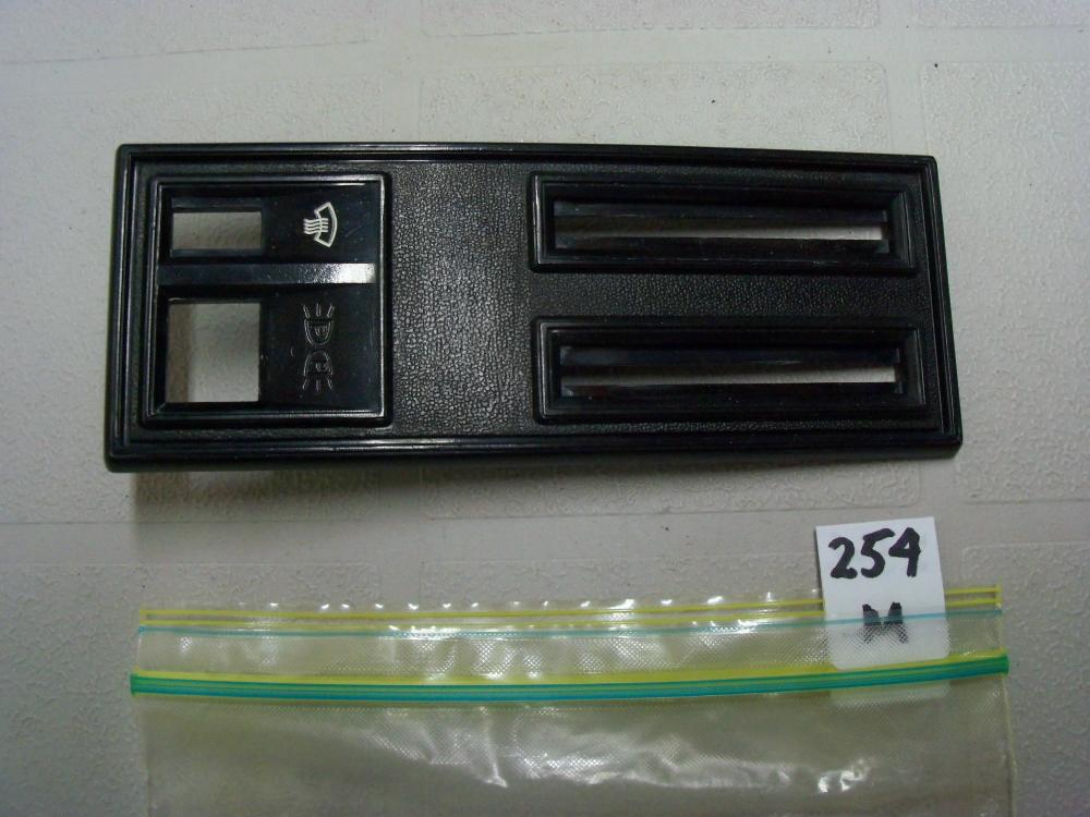
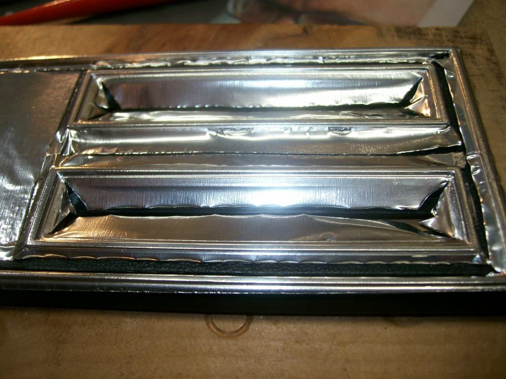
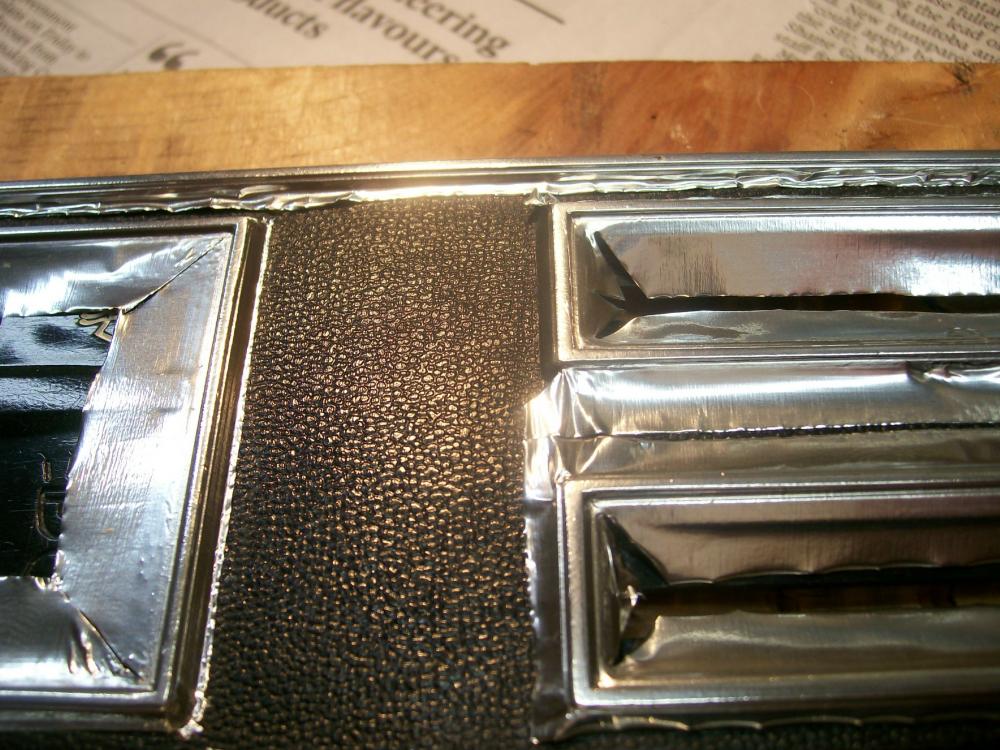
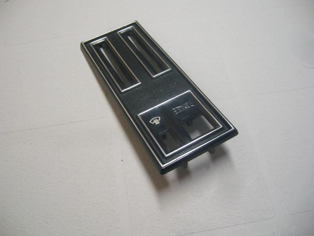
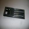
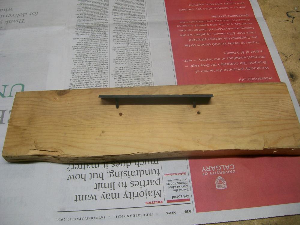
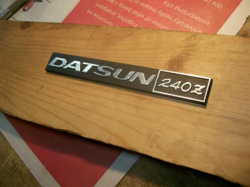
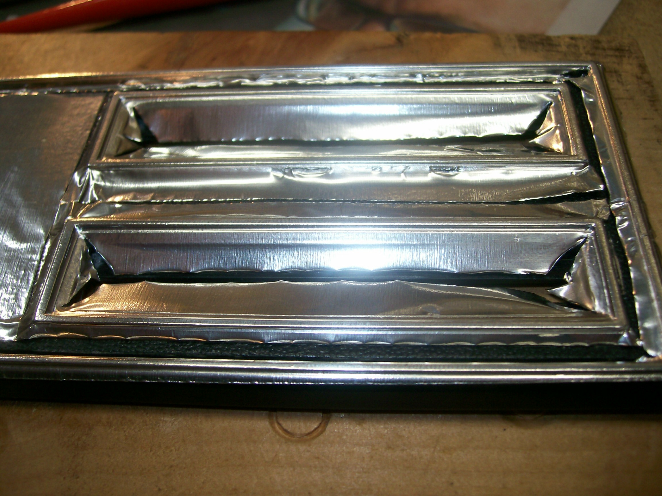
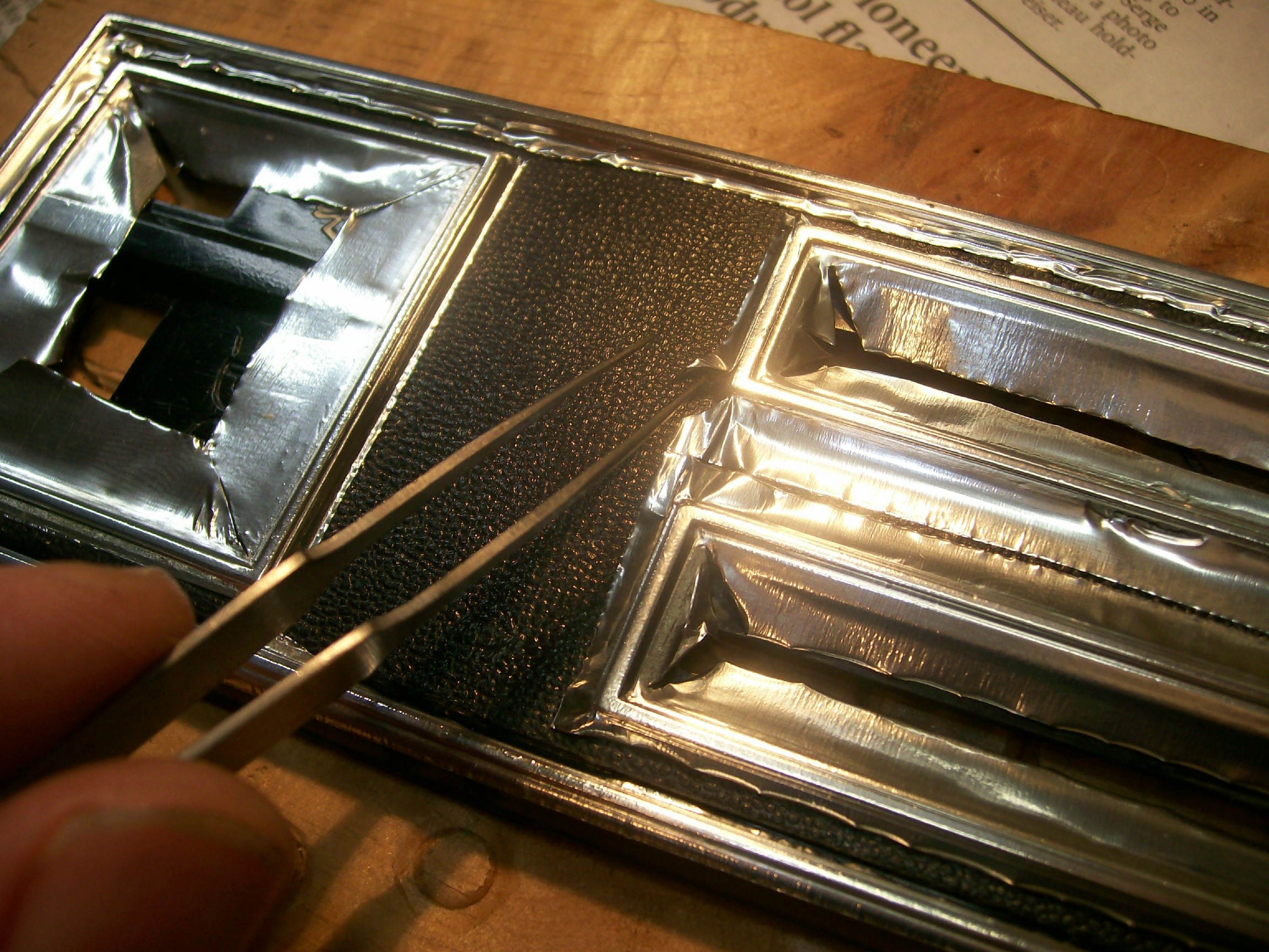
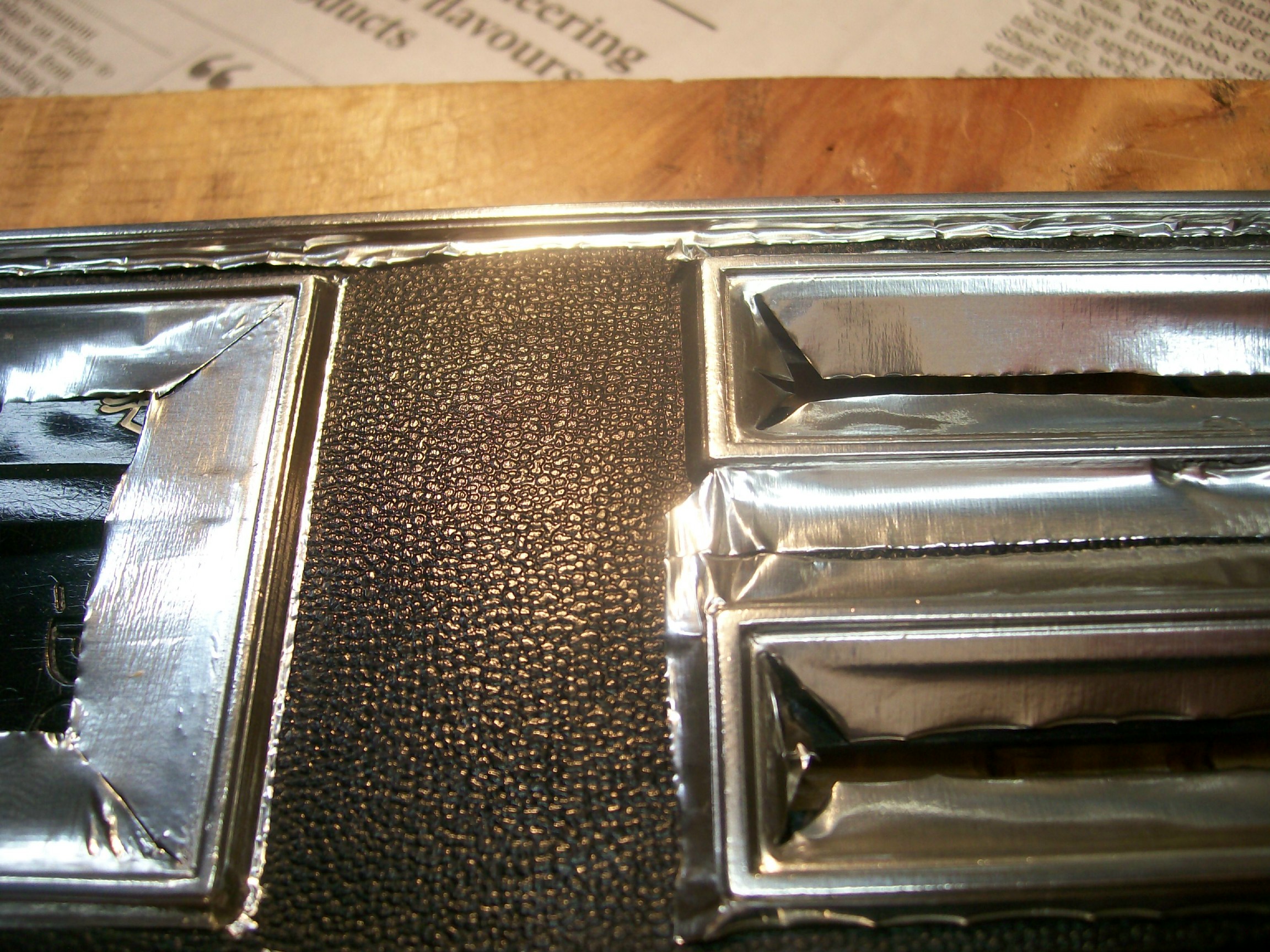
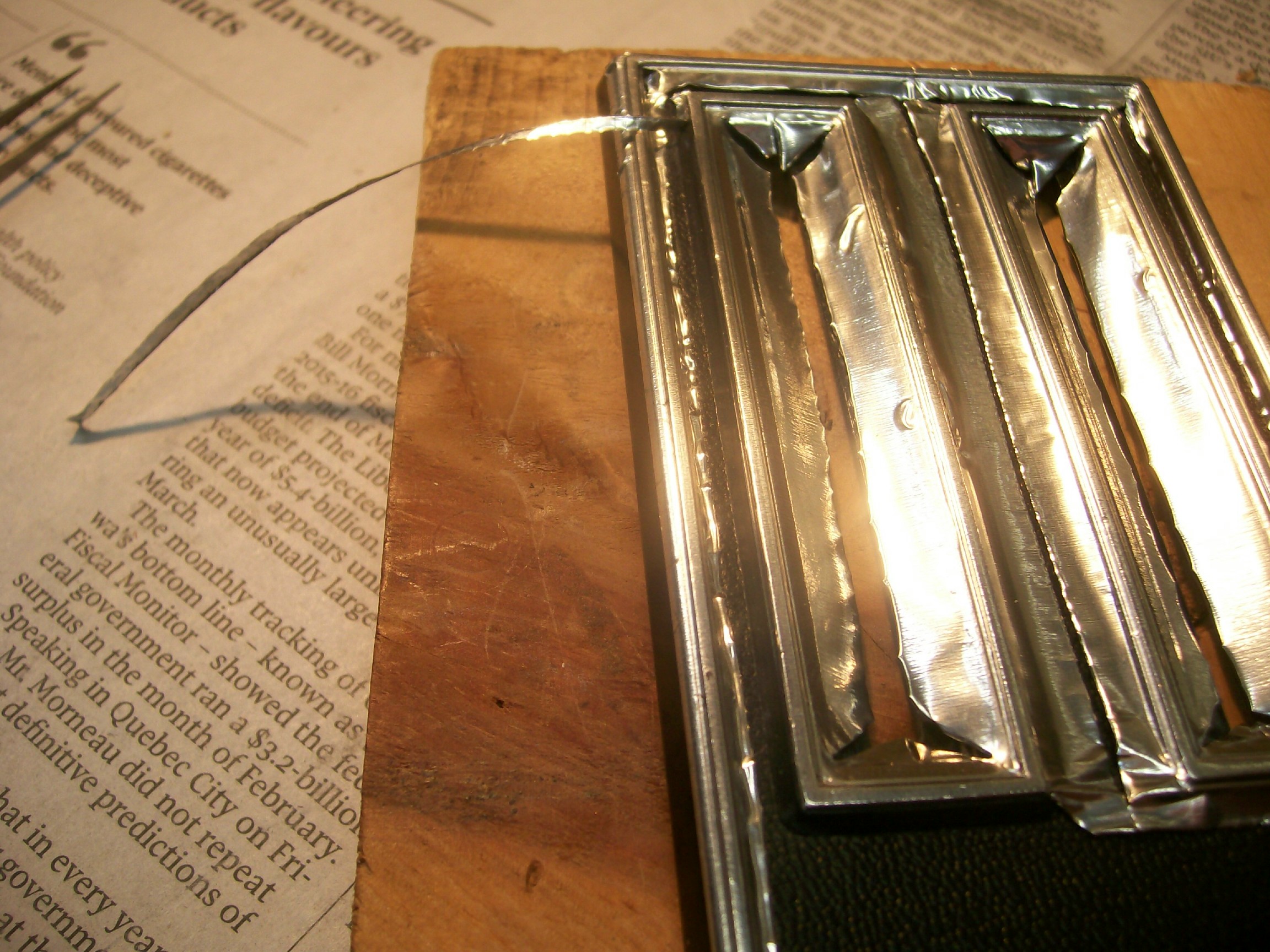
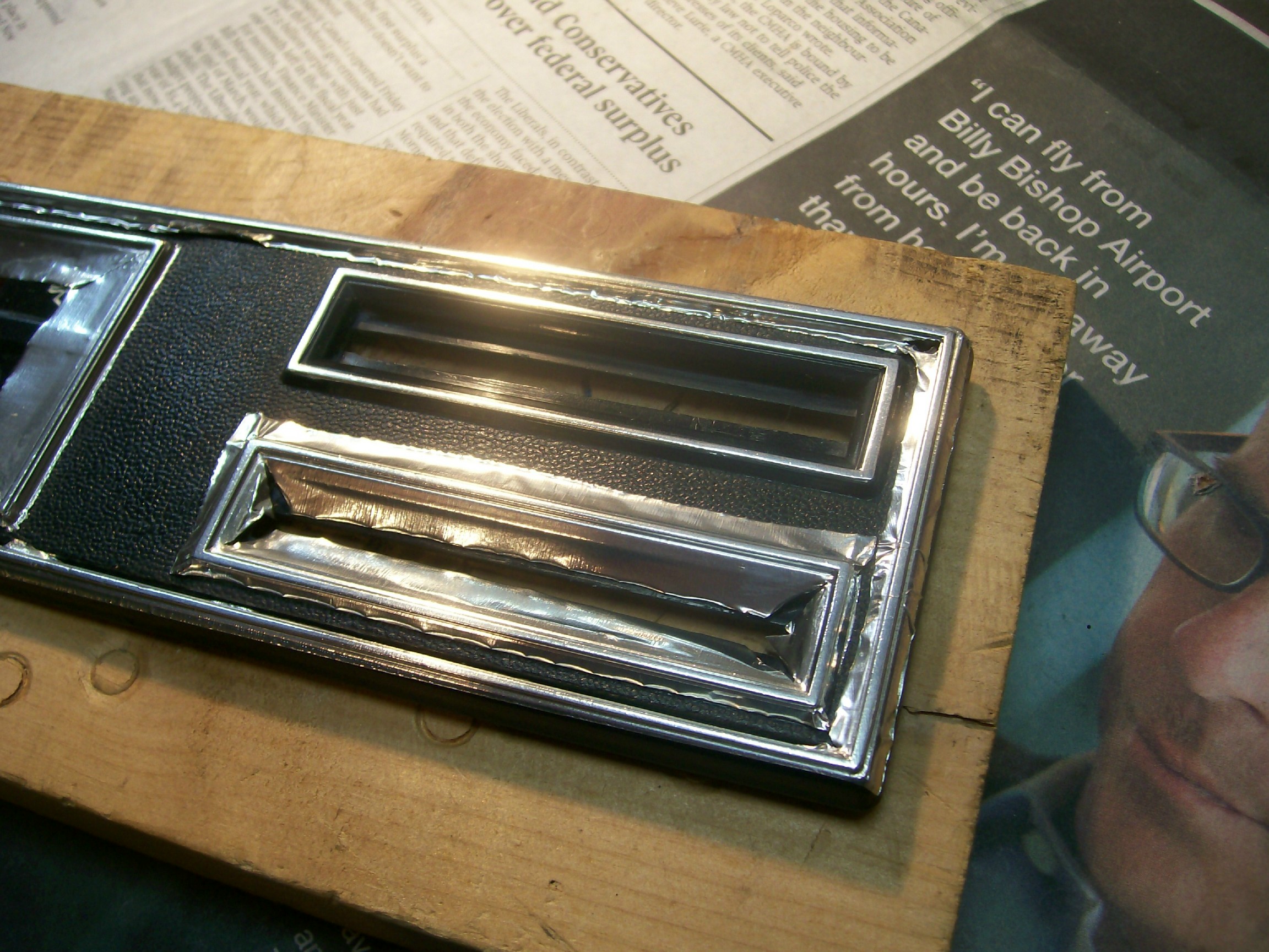
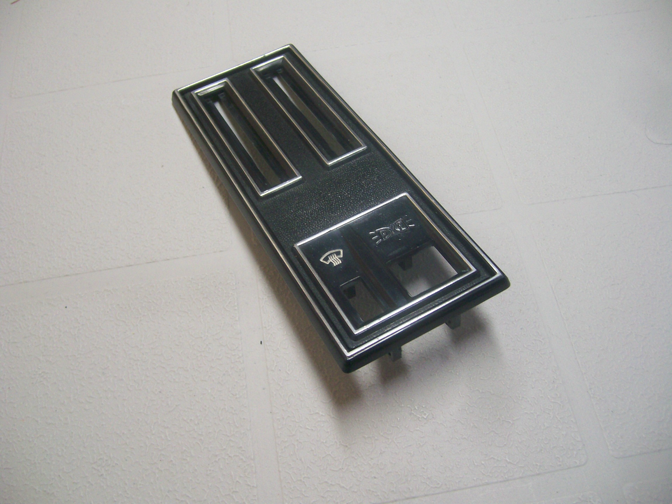
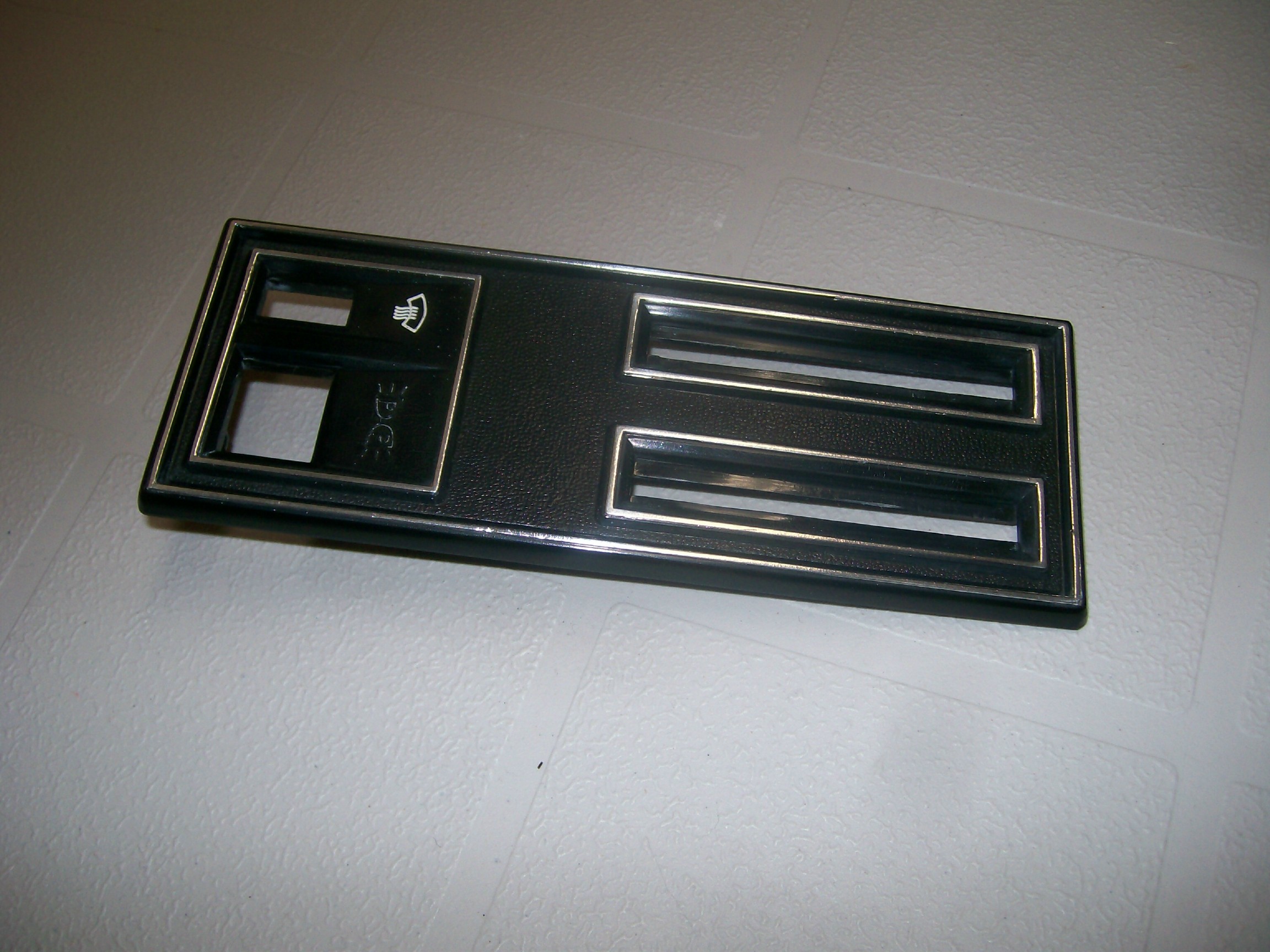
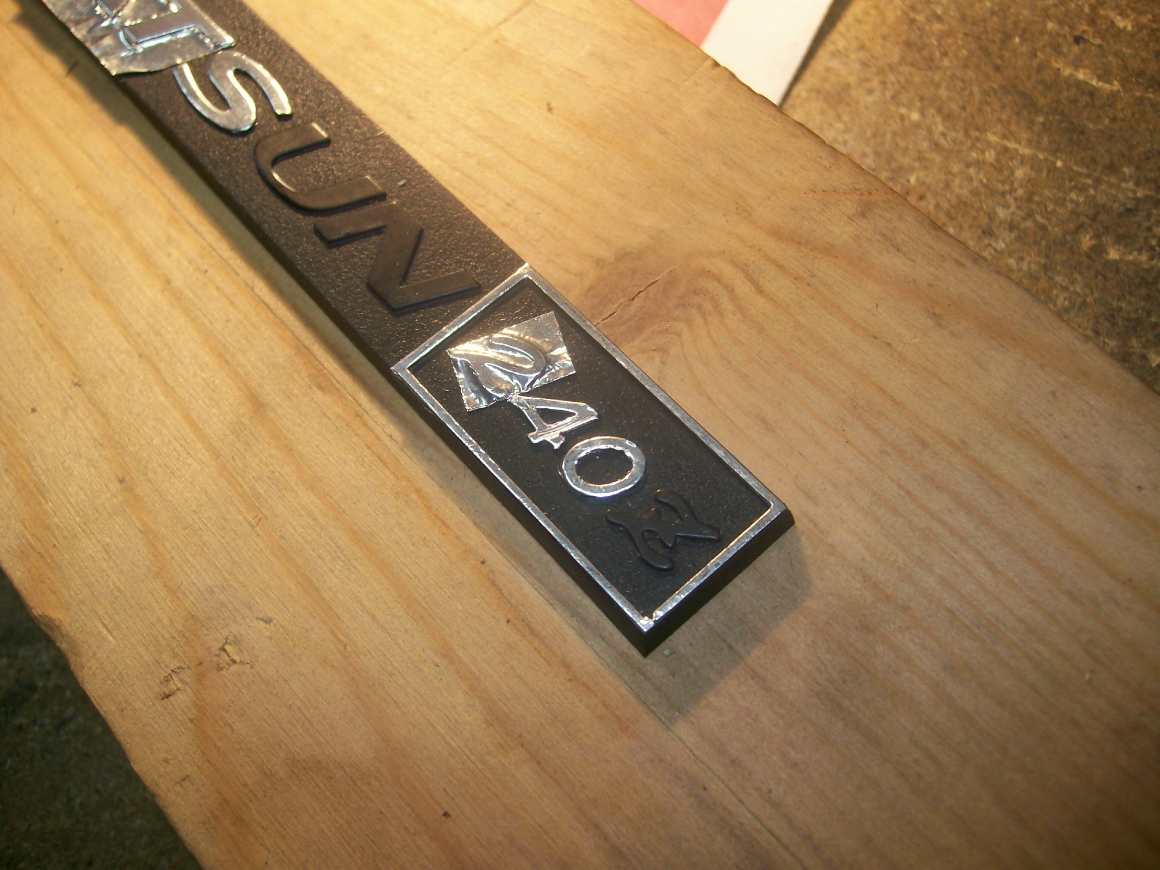
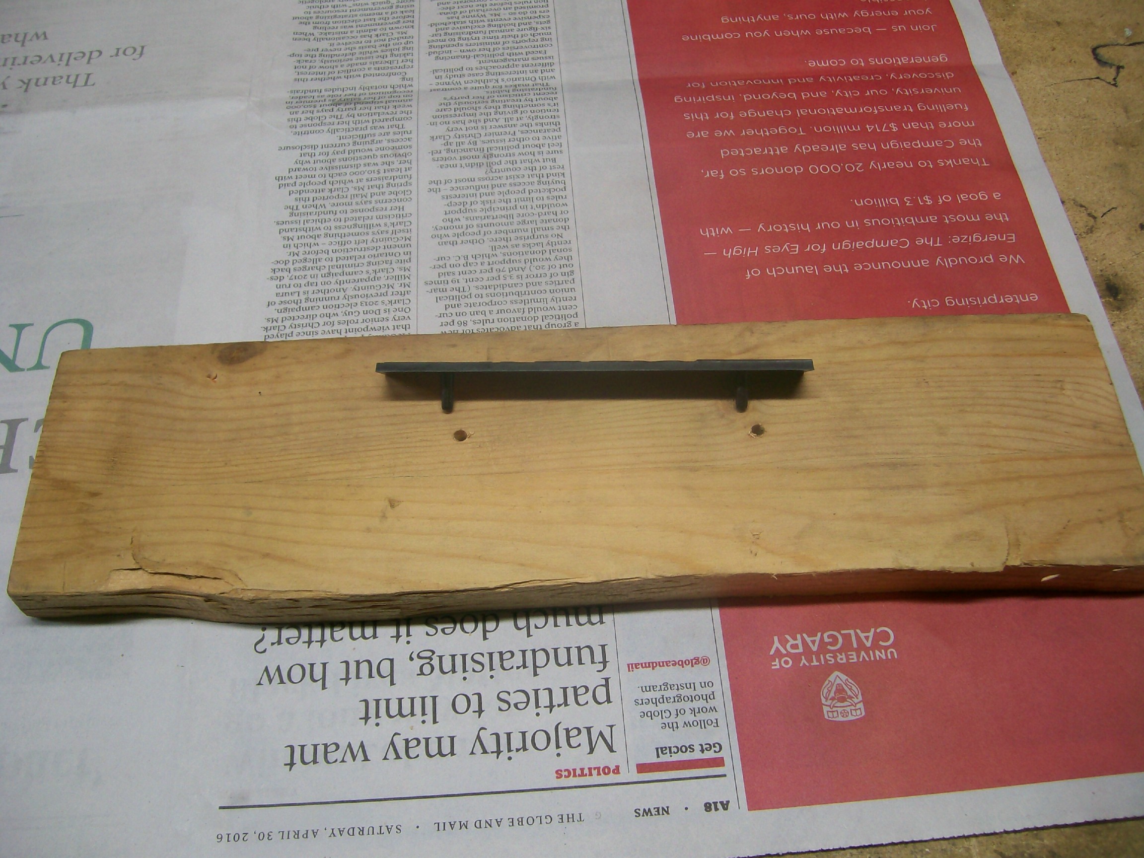
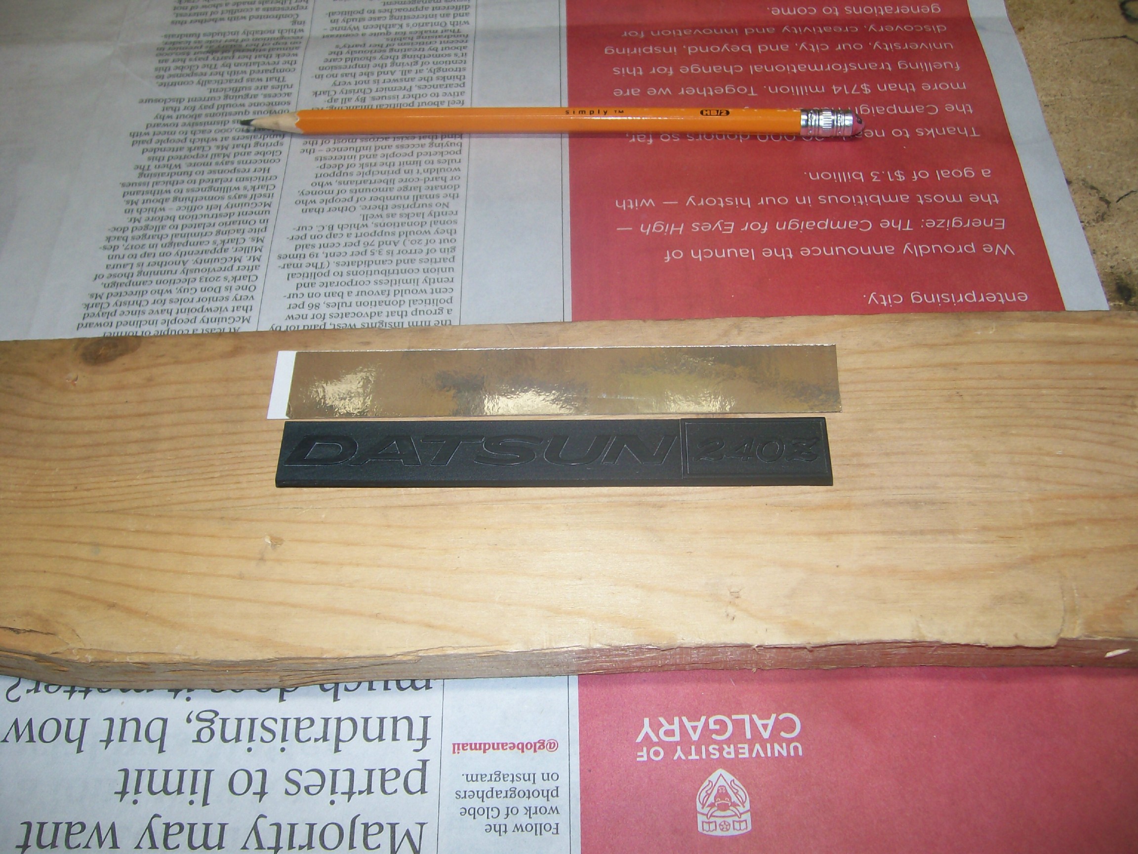
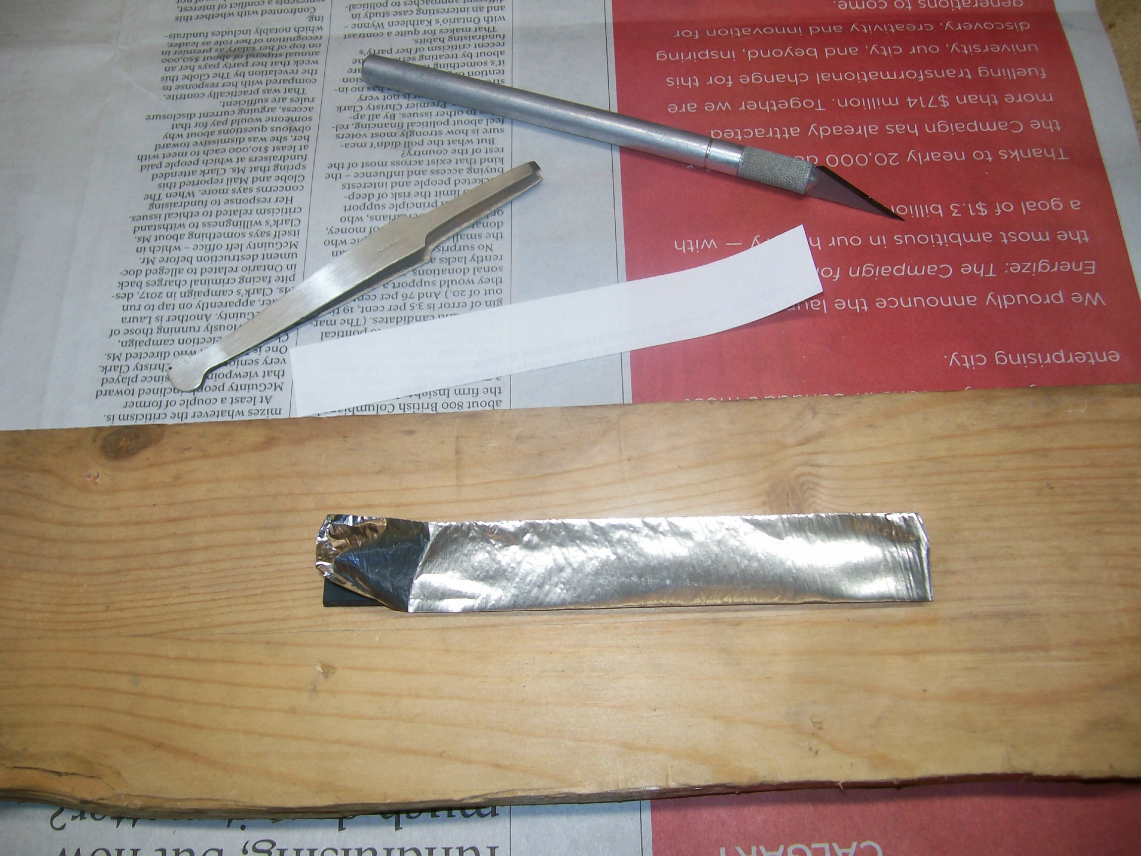
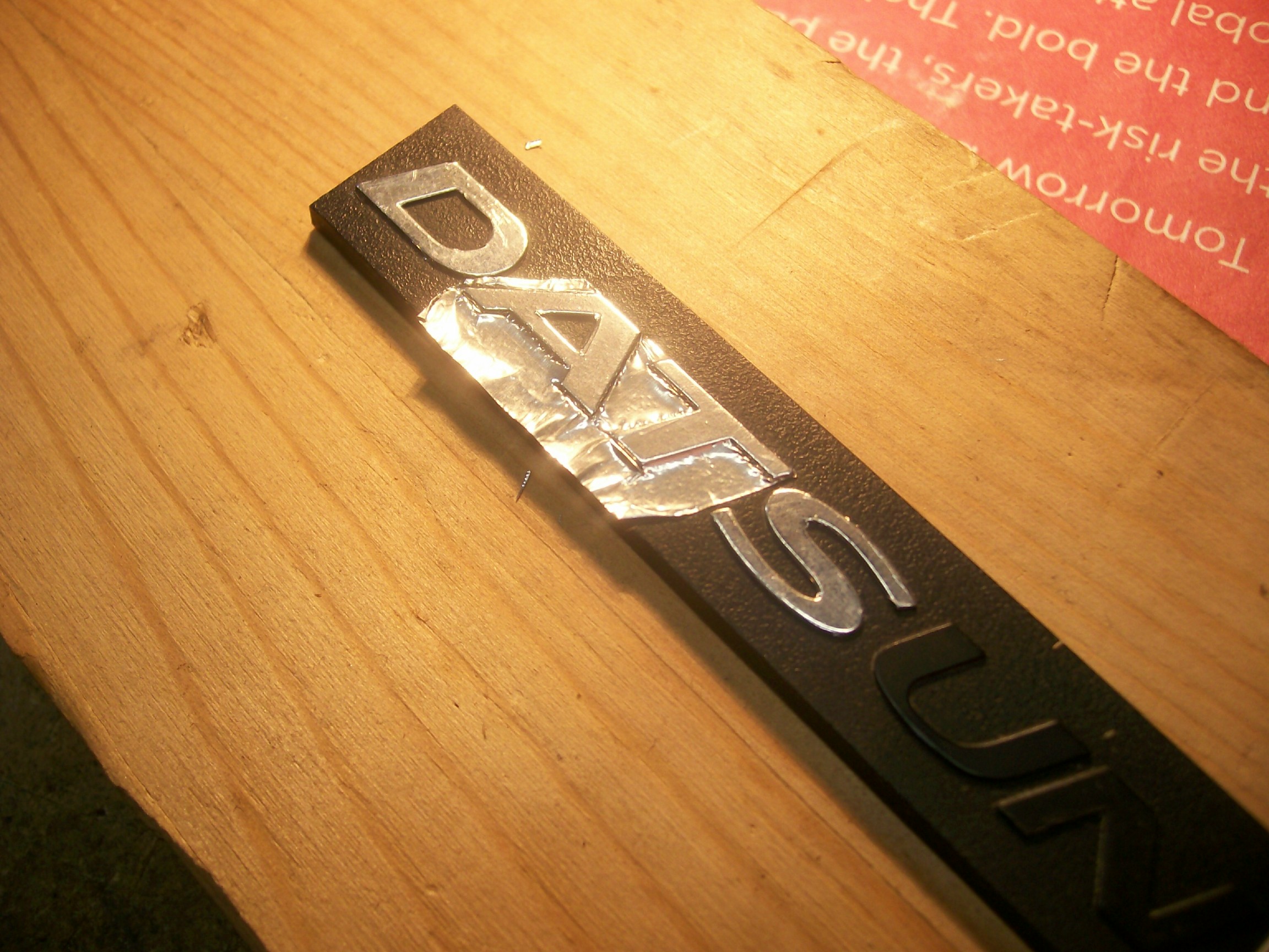
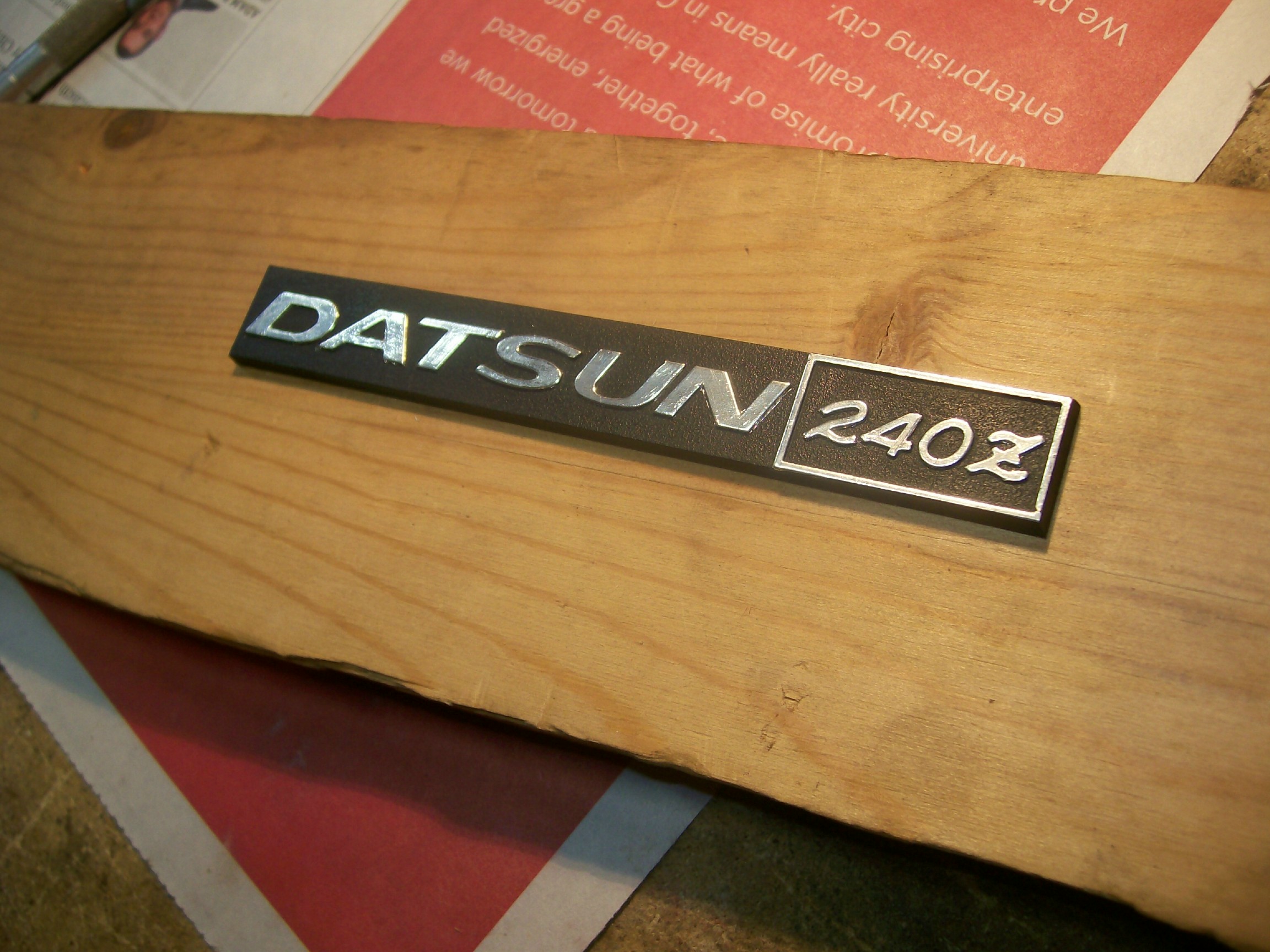
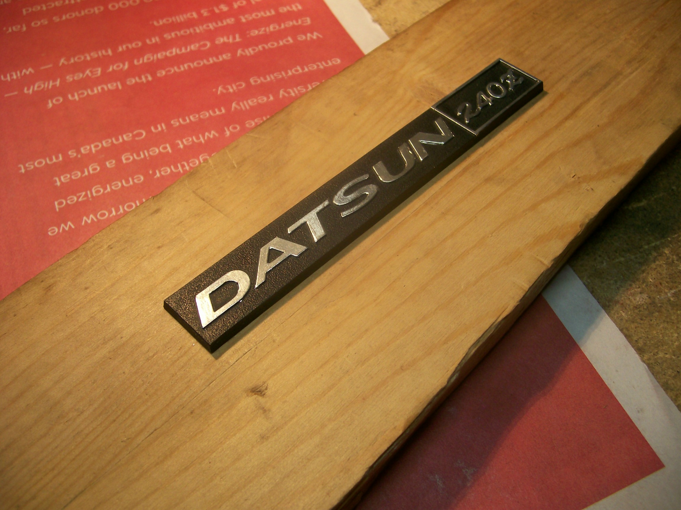
The topic of refurbishing the chrome lettering on the Z's dash features came up again today. I'd read several past posts by members, including those the recommended the use of the silver Sharpie pen. I tried this on the 'Datsun 240Z' logo plate for my glovebox door. While the results looked ok, it proved not to be very durable. As a matter of fact, the ink came off on the kleenex tissue that I'd wrapped the piece with for protection during storage. Maybe some clear acrylic would have helped. Just the same, I now had to start over. This time, I decided to try something different. I'd read about the chrome foil that scale modelers use for simulating chrome trim on plastic kits. Pictures of their results looked really promising, so I decided to give it a try. A page-sized sheet of adhesive-backed foil cost about $10 at the local hobby shop, so I figured I didn't have much to lose. The results were better than I'd ever cared to hope for. Here are some pix of the work I've completed so far -- two pieces: the glovebox logo and the centre console insert plate. The foil itself has about the same feel as the foil wrap used in a package of cigarettes. It's very thin and you need to be very careful peeling it off the backing sheet. Also, the adhesive on the back is very, well, adhesive, so you need to plan ahead as to what your next move will be after you've peeled your piece off the backing sheet. One wrong move and it'll be stuck to something you hadn't planned on sticking it to. It does not un-peel easily, so you'll probably have to toss that piece and cut out a new one. You'll need a sharp hobby knife to make this work. As the instructions that come with the foil mention, 'sharp' means 'really sharp'. Use only a brand-new blade. In fact, the foil manufacturer recommends that you hone the brand-new blade to make it even sharper. I didn't do this and I didn't find it necessary. However, you're going to be cutting through actual metal and that means that you may need to replace your blade with a new one from time to time during the job. The tip-off will be when the blade starts to tear the foil. Unfortunately, that will be too late (i.e. your job will be ruined), so the moral is, don't cheap out on blades. This job takes a very steady hand and a lot of patience. It's also really important that you set up your work piece so that it well anchored, movable, and placed so that your arm and hand will be well supported and at the right height for both comfort and position relative to the work piece. Let's start with the console insert plate. This has mounting bosses and brackets that extend off the bottom, so I found a piece of scrap wood and drilled holes in the appropriate places so that the plate would sit flat on the board. I also made sure that the plate wouldn't jiggle or move around on the board (really important). The console insert plate has a number of full-perimeter chrome accent stripes. As you can see, the chrome was completely MIA on my plate... Although it would have been less risky to do each 'box' as four separate chrome strips, I didn't want to have cut-lines at the corners. Too easy to catch on and lift and edge when driving, and also not a clean appearance. So, after taking a deep breath, I cut a big sheet of foil and dropped it in place... The picture shows the foil in place and I've already 'burnished' it along the raised accent ribs. I found this best accomplished with a piece of high-acrylic cloth from an old shirt. Whatever you use, make sure it's smooth, soft and thin. Be really careful when you do your burnishing. It's all to easy to catch a bit of raised foil by accident and create a rip (and that means you start all over again). Do not burnish in the areas that won't be chromed (it's going to be enough of a chore lifting the excess foil away, without having it stuck to the work piece). You want to burnish only on the 'flats' of the raised ribs but not along the sides of the raised ribs. In the picture above, I've also started to do some initial trimming. Again, you need to be careful at every step along the way. Little rips turn into tears, and a tear can suddenly grows by a half-inch and ruin your work. (BTW, one of the photos shows an actual 'burnishing tool' that I had left over in my tool kit from the days of 'letraset' - it proved to be poorly suited for use with the thin modeler's foil I put it away immediately). The knife work requires practice to develop the right 'touch'. You need to find the right weight, the right 'steering' angle, and the right tracking edge (it's not a freehand cut). You'll learn how to find a ledge that you can run the point along. Once you get the knack of it, you can run a 4" straight cut in one move. In point of fact, you really need to strive for making these cuts in one move, because it's difficult to resume a cut without creating a little ragged edge. Also, the foil doesn't lend itself to 'clean-up' work afterwards. You really need to try to get it right the first time. The photo above gives a little closer look at the burnishing and the start-off cuts. Below, you can see me about to use my tweezers to pull the excess foil away after the first of my detail cuts... Here's the 'After' shot, with the excess foil completely removed... Below, you'll see the same process carried out for the first of the longer cuts... And, finally, the first rectangle completed (at this point I am feeling both happy and relieved)... It perhaps goes without saying that the raised strips around the outer perimeter of the plate were the most challenging to get right. Nevertheless, I was 'in the zone' by this time and managed to get everything done without any major incidents (just a couple of small ones ). Here's a photo of the end result: and... (The second photo won't load full-size for some reason) I was pretty happy with the results, given that this was the first time I'd ever tried using this foil. I was particularly relieved to find that I could cut dead-straight edges just by finding the right little ledge to let the knife tip run in (it's easier to feel these ledges than it is to see them, but they're there). Once you find the ledge, the challenge is to keep the knife tip moving steadily forward in the right direction. It's pretty easy to have the knife tip wander out of the ledge if you have the blade's 'steering angle' a few degrees off. When that happens, you've got trouble. Now for the glove box emblem. Different challenges here, given the many curves and inside corners. Same technique though. First, the backing board... Then mount the work-piece and cut a piece of foil... Lay the foil in place and burnish with your cloth... Look for the 'ledge' around each character and start to make your cuts. Curved edges are the most challenging, obviously. You may have to re-do many of the characters before you get everything to the point where your happy with your results. If you need to do a fix-up (like I'm doing with the '2' in the shot below), make sure you cut you new piece of foil to exactly the right overall size, so that it doesn't accidentally touch the foil on one of the adjoining characters... which will mean you'll now need to re-do both characters). Of all the characters in this logo, the 'Z' was the hardest to do. Save it for the last. Here's the final result (not the greatest of pix as I found it hard to get the lighting angle right)... All told, I think it took me about 3 or 4 hours to complete these two pieces. I found it useful to walk away from time to time, as it's pretty demanding of concentration and coordination. Nevertheless, it's real (metal) shiny chrome and it won't fade. I'm pretty confident about the adhesive, but I guess there's going to be a test of that sometime in the future when the car gets parked in hot sun for a few hours. The durability looks like it will be just fine, provided I never accidentally catch an edge while cleaning.


-
I think you've done a nice job with this. It'll look great when it's back in the car and, trust me, no one is going to ask you to pull the unit out so that they can inspect the quality of the plating job. I had the same issue with refurbishing the chrome details on my radio's faceplate. Although I haven't gone back to this particular piece, I did manage to generate some nice results for my car's dash logo (glovebox door) and console insert piece using scale modeler's chrome foil applique. I'll post some pictures in a separate thread.
-
Now if I could only find a complete car in the same shape! But priced differently. If nothing else, the pictures certainly offer an nice reference for the correct shade of 'Z Gray'. I wonder if others here still feel that the gray used on these wheel covers is the same gray that was used by the factory for the front grill and the rear trim panels?
-
.Are you saying that the zinc anode plate will/should retain a shiny appearance under ideal current conditions?
-
I like this approach. Who was your source for the mass-loaded vinyl sheet? How did the price per sq.ft. compare with the usual products like Dynamat?I like this approach. Who was your source for the mass-loaded vinyl sheet? How did the price per sq.ft. compare with the usual products like Dynamat?Good tip concerning the use of floor tiles as turn plates. For a light car like a Z, I wonder if it might not be a bad idea to load up the driver's seat with 150 - 200 lb of ballast (sand bags?) before doing a toe adjustment. Re compensating for front-to-rear differences in track/tread when doing a string alignment: The 240Z's wheelbase is 2305mm, while the front and rear track measurements are 1355mm and 1345mm respectively, That would call for a 5mm step-out adjustment of the jack/axle stands at the rear. This doesn't seem worth fussing over. The error created by a 5mm lateral difference when played out over a 2305mm lengthwise distance amounts to only 0.005mm (i.e. two ten-thousandths of an inch). I found a nice pictorial explanation of how to do a string alignment here: http://www.hotrod.com/how-to/chassis-suspension/ctrp-1204-determining-wheel-alignment-string-your-car/


Important Information
By using this site, you agree to our Privacy Policy and Guidelines. We have placed cookies on your device to help make this website better. You can adjust your cookie settings, otherwise we'll assume you're okay to continue.