Namerow
Community Member
-
Joined
-
Last visited
Everything posted by Namerow
-
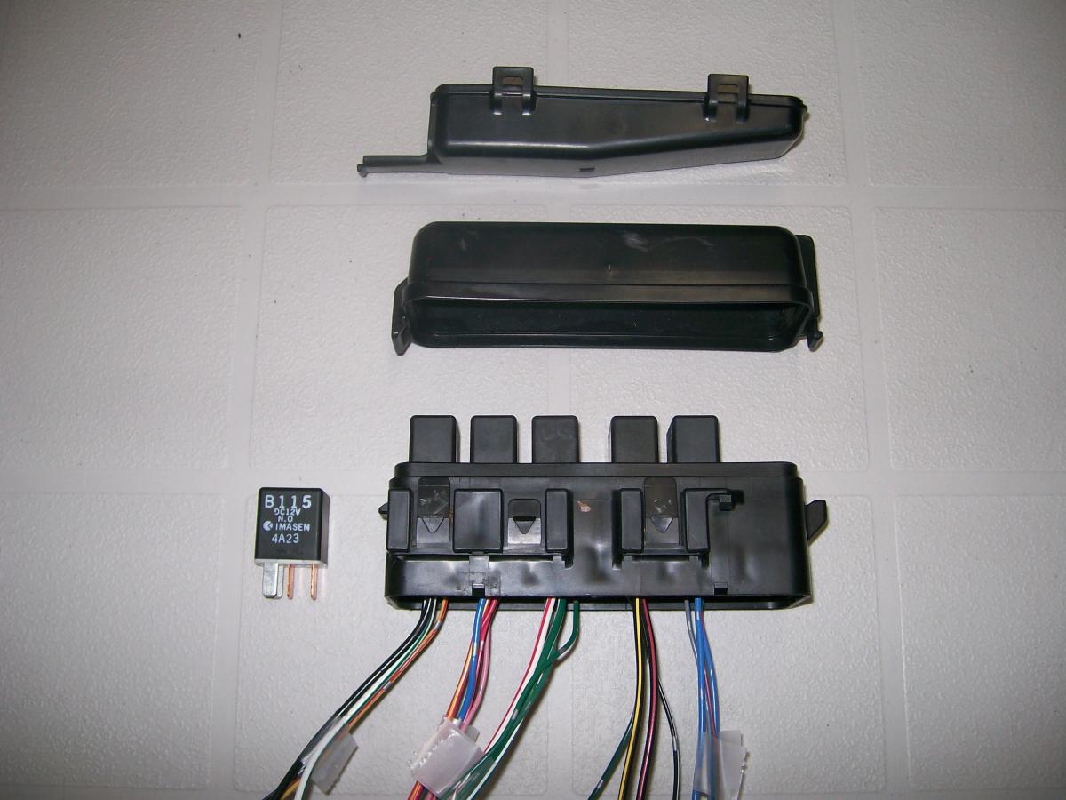
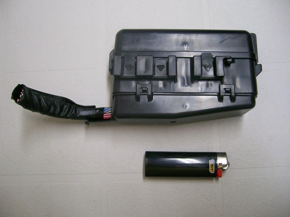
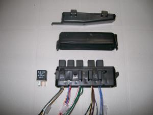
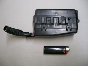
Already with you on that. The design I've come up with uses an 'intermediate harness' with Nissan T-3 connectors to plug into the engine harness at the appropriate places (when I said I was going to start cutting wires, I was talking about the wires for this harness and not about cutting into the car's engine harness). BTW, a recent search through the local pic-n-pull produced a very nice relay block, taken from the engine compartment of a 91 Mazda MPV. The casing has removable upper and lower caps, with all of the wiring entering and exiting at a common conduit at the front. The internal wiring and relay set-up was, of course, specific to the Mazda application. However, the wire terminals can be extracted from their sockets and moved around to suit a new requirement. I grabbed two of these relay blocks and have used them to produce a single block with 5 identical relays (4 for headlights, 1 for fog lights, one empty socket for possible future use for an electric engine cooling fan). The new, intermediate harness will be connected up to the relay block using two pairs of spare Nissan 3x2 connectors. The fog light relay will take its switching signal off the rhs pair of bullet-connector plug-in points up at the front of the car. Power for the fog lights will come off the alternator. Headlights and fog lights will now all be grounded to the chassis with dedicated local ground wires. The relay block will be mounted in the engine compartment, using the mounting bosses from the now-discarded voltage regulator (I'm using a 280ZX internally-regulated alternator, along with the MSA/Dave adaptor plug).
-
Thanks for the quick reply, Captain O (and thx also to Steve for chiming in on my original question). I wanted to be 100% sure before I start cutting and soldering for my 4-relay set-up. The two FSM-sourced electrical diagrams just didn't seem to line up with what I had in front of me (nor did the one from the Haynes workshop manual, or any of the other permutations that I've found on this site), so I'm really happy that you reminded me about the one I had sitting in a drawer in my Owner's Manual. Some trivia I noticed during this exercise: The wiring diagram in my 1970 Owner's Manual shows the #2 fusible link (at the Alternator) that the 71 FSM diagrams managed to omitUnfortunately, the 1970 OM diagram doesn't show the Accessory Relay that powers the Rear Defrost heating grid (although it at least shows the grid and switch)The 1970 OM diagram also completely omits the Blower wiring and control switchThe 1970 OM diagram has the pairings of the aux gauges mixed up (should be Amps/Fuel + Water/Oil, not Amps/Water + Fuel/Oil)Also: The embossed graphics for the Light/Wiper settings on my Combo Switch show a third (but unpainted) 'dot' for the Wiper speeds, hinting that Nissan was already planning to add an 'Intermittent' feature at some later date. Counting those in my 'spares' box, I have four Combo Switches on hand. They're all different!
-
I should have added the full electrical diagram from the 70 Owner's Manual. Here it is, just as I scanned it from the hard-copy manual that came with my car... S30 Wiring Schematic - 70 240Z - B&W - 70 Owners Manual - v3 (darkened).pdf
-
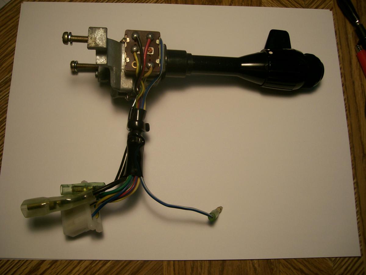
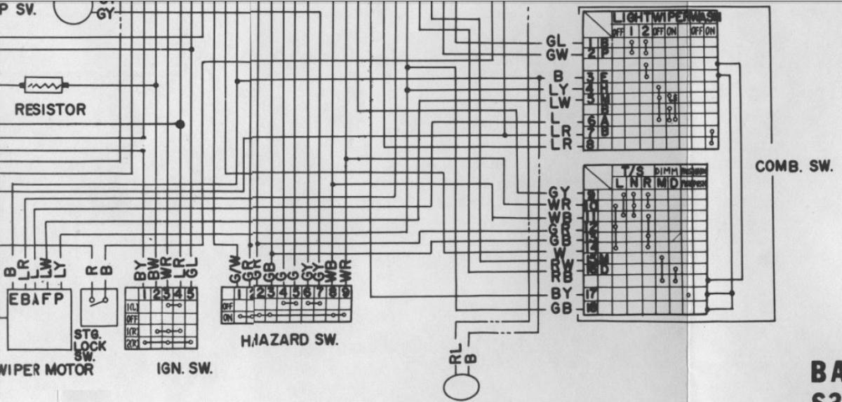
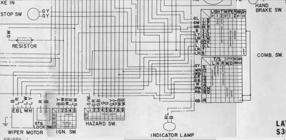
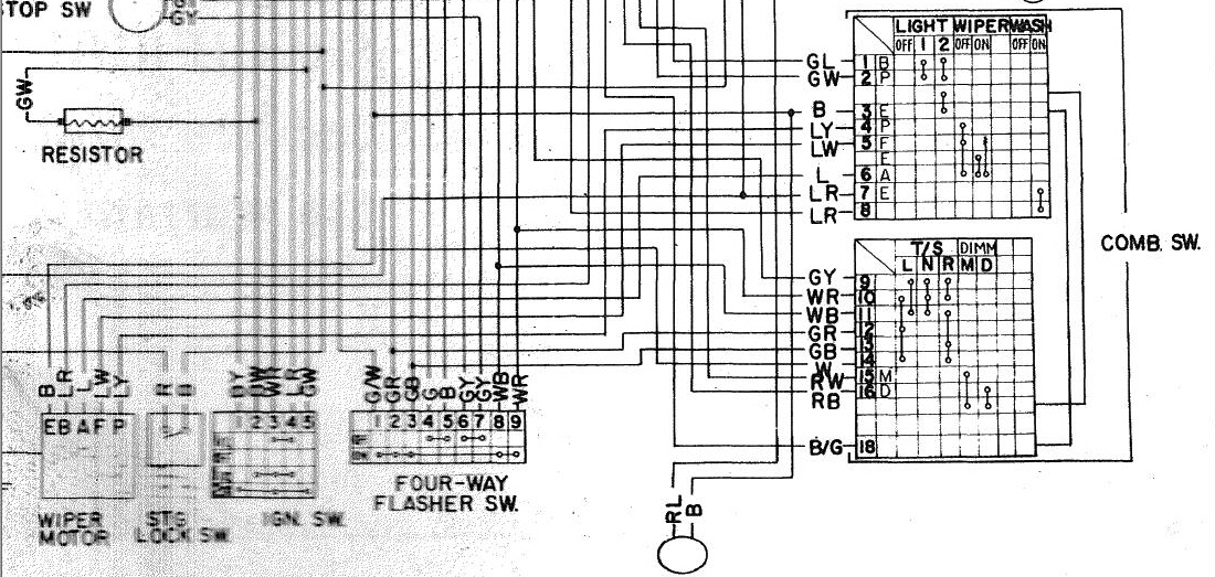
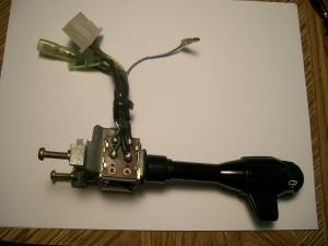
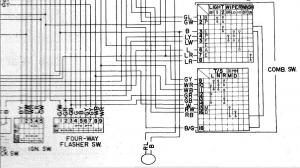
Ay chihuahua! There's another wiring diagram!! I forgot all about the tiny little version that's tucked into the back pages of the MY-70 owners manual (and humorously labeled, 'Minor Maintenance'... ha!) So now I've burned up another morning staring at yet another version of the wiring and connection logic for the early Z Combination Switch. This wasn't helped by the fact that the wires on the 'Lights' side of my car's combo switch are different from those shown in all three of the wiring diagrams (see photos). I finally decided to check the 6X connector from the dash harness that plugs into the matching connector on the Combo Switch. Ahah! The wire colors change as they pass across the connection. For my switch: Switch Wire Harness Wire RL L YG LW YB LY So now I had something to compare with the 3 wiring diagrams. After a lot of playing around with my continuity checker, I determined that the Combo Switch in my May-70 Series 1 is best represented by the diagram that appears in the 1970 Owners Manual that came with my car (for reference, my manual is labeled as a 20-Mar-1970 printing). The fun didn't stop there, though. Even this wiring diagram isn't absolutely accurate in its depiction of the connection logic for the Combo Switch. The logic for the Wiper function is shown incorrectly. In fact, if you look at all three diagrams, you'll find that the details for the Wiper function are, um, 'erratic'. In the FSM versions, only 'ON' and 'OFF' are depicted. In the Owners Manual version, all three Wiper positions ('OFF' / 'LO' / 'HI') are shown, but connection details are shown only for the 'OFF' and 'LO' positions, and even these are depicted incorrectly. I scanned the diagram from my 70 Owners Manual and then created a modified version that depicts the Wiper connection logic the way I traced it from my actual Combo Switch. Combo Switch details from all four versions are shown below... So, anyway, I've now verified that my particular Combo Switch uses a switched ground for the headlights that is controlled on both sides of the Combo Switch... On the 'Lights' side - Ground continuity for the headlights is only established when the Light control knob is in the '2' position On the 'Turn Signal' side - The Dimmer Switch provides 3 possible ground paths/settings... Open, Hi-Beam, and Lo-Beam). And then, of course, there appears to be a 'Flash to Pass' function, which I think allows the hi-beams to be triggered by a partial pull on the T/S stalk (and doesn't care what position the Dimmer Switch is in). Can somebody explain how that works? But the 'Main Question', now, is this: With the set-up in my car (per the wiring diagram from the 70 Owners Manual), what do I need to do -- if anything -- to make my two headlight fuses always hot? 71 FSM Supplement - Basic Model 71 FSM Supplement - Late Model 70 Owner's Manual (dated 20-Mar-1970) 70 Owner's Manual - Wiper switching logic corrected


-
Some questions for Captain Obvious: I'm trying to adapt your 4-relay scheme to a May 70 Series 1. Its wiring arrangement seems to be pretty much in agreement with the second of the two electrical diagrams that appear at the end of the 1971 FSM 'Supplement' (specifically, the schematic that's labeled, 'Late Model S30 Series for USA'). I have questions relating to the re-jig of the Combo Switch wiring that you've shown earlier in this thread. Your instructions and pix discuss to two main objectives: 1. Make the Dimmer Switch switch to ground 2. Make the 'Headlamp' fuses always hot Your instructions appear to be specific to a Series 2 and/or Series 3 car. Certainly, your discussion of the Combo Switch wiring colours is quite different from what I find on my Series 1. I've read that there was a switch in electrical 'design philosophy' on Nissan's part when they updated things for the Series 2 launch. Specifically, the Series 1 headlights circuit used a 'switch to ground' approach. The Series 2 and Series 3 evidently do not, hence the re-worked Combo Switch wiring that you discuss as being necessary to make your scheme work. (BTW, I don't think the change had anything to do with overheated fuses and overworked switch contacts, because that didn't change for the new design. I think it had to do with electrical corrosion problems that were a problem for the headlamp connector plugs up at the front of the car. Perhaps you or someone else can comment?). Anyway, looking at my car's Combo Switch, I find that the hi/lo dimmer switch 'already' switches to ground (by way of a Red jumper wire that leads out of the Dimmer Switch and connects via a bullet connector into a Black wire that goes to the back of the Light Switch and then directly to the main ground wire in the Dash Harness. Also, it appears that the two Headlight fuses in my Series 1 fuse block are 'already' always hot. They're supplied by the big White-Red wires that come to into the fuse block from the Alternator by way of the Ammeter 'NEG' terminal (Battery connects to the Ammeter's 'POS' terminal). So, it looks to me like the 'Late Model S30 Series USA' Combo Switch found in my car doesn't need any re-working in order to adapt directly to your 4-relay scheme. Would you mind having a look at the Series 1 wiring diagram to see if you agree? Thx in advance for your help.
-
My 5/70, with original engine: '2400' valve cover = yes 'Warm/cold flap' on the air cleaner snorkle = noalso 'no' re warm-air-delivery flex hose, and 'no' re the matching shroud plate mounted around the bottom of the exhaust manifold (has a 'spigot' where the flex hose attaches) Back in the day, I owned a 72 Z as a daily driver. On really cold Canadian mornings in January or February (days that were much colder than I expect Skinner-Union ever imagined) the cold-start drill consisted of: Choke to 'full'open hoodset warm-air flap to 'warm' position3-second shot of ether into the air cleanerset warm-air flap back to 'cold'close hoodstart engine
-
The wire you're looking for (that is, the wire that comes through the firewall) wasn't installed by Nissan when it built your car. It was installed by the person who installed the 'aftermarket' A/C system in your car. That person would have used whatever color of wire and type of connector they had available. This, of course, is the same person who soldered that short, add-on Green wire onto your car's Blower switch. Chances are that they used more of that same Green wire for the longer run from that goes from under the dash and through the firewall into the engine compartment. Or maybe they used a different colour of wire. We don't know. It's a pretty safe bet, though, that they used a spade connector for the end of the wire that's (hopefully) hiding somewhere under the dash. There is one other possibility, though, and you need to be aware of this: The wire you're looking for (the one that goes through the firewall) may have been stripped out of the car by someone who got there before you or your dad started working on the car. I don't know why anyone would do this, but it's a possibility. If you can't find a likely-looking wire, then you'll have to put in your own (not a big deal) and figure out how to hook it up to the A/C thermal switch in the engine compartment. My car doesn't have A/C, so I can't tell you what to look for at the switch end. Anyone else want to jump in here?
-
Explained in my earlier post, but here it is again: The A/C control wire provides power to a thermal switch that controls the electromagnetic clutch on A/C system's compressor drive. You can find that wire up in the engine compartment by tracking backwards from the A/C compressor (which is the bigger of the two 'cans' that are powered off the drive belts at the front of the engine -- the other 'can' is the alternator). When you find a likely looking wire, track it back to the thermal switch, and then track back from there towards the firewall. Check the colour of the wire at the last place where you can see it in the engine compartment. (Hopefully) the wire will stay the same colour in the Interior all the way to the place where the Green wire used to connect to it. Then: Go back inside the Interior and look for that same-colored wire. Clues: 1) it should be lying somewhere within reach of the disconnected Green wire, and; 2) it won't be connected to anything else. It'll also probably have the same kind of end connector that's fitted to the loose end of your Green wire. Based on your correction of my earlier note, that means you're looking for a loose wire with a female spade connector on the end. New note: There's always the possibility that your dad found this A/C control wire during his earlier efforts and, not knowing what it was for, taped off the end and stuffed it up somewhere out of harm's way under the dash. You never know.
-
Joe, the reason why you can't a male connector for the Blue wire is this: 240Z's did not come with factory-installed air conditioning systems. The air conditioning system was installed by someone in the USA after the car arrived off the boat from Japan. That 'someone' was probably the dealer who received your car back in 1971 as part of their new-vehicle allocation from Nissan. It might also, perhaps, have been installed-to-order for one of the previous owners by an air conditioning shop. It might even have been installed by a local garage, or even by the owner. In any case, whoever put the air conditioning system in your father's car didn't know about the hidden Blue wire on the car's HVAC mini-harness. All they knew was that the A/C system they were about to install needed a 12V power wire with an ON/OFF switch. The ON/OFF switch was already there (in the form of the Blower switch), but the wire wasn't. So they simply soldered on one to one of the POWER-OUT terminals on the back of the Blower switch. To avoid creating confusion with any of the factory-installed wires down in the same area (none of which are green), they used a Green wire. Then they connected the other end up to the control wire that provides power to a thermal switch that controls the electromagnetic clutch on A/C system's compressor drive. You can find that wire up in the engine compartment by tracking backwards from the A/C compressor (which is the bigger of the two 'cans' that are powered off the drive belts at the front of the engine -- the other 'can' is the alternator). When you find a likely looking wire, track it back to the thermal switch, and then track back from there towards the firewall. Check the colour of the wire at the last place where you can see it in the engine compartment. (Hopefully) the wire will stay the same colour in the Interior all the way to the place where the Green wire used to connect to it. So: Go back inside the Interior and look for a same-colored wire that's: 1) within reach of the disconnected Green wire, and; 2) not connected to anything else. It'll probably have the same kind of end connector that's fitted to the loose end of your Green wire. Based on your picture, that means you're looking for a male spade connector. One caution: There's always a chance that the A/C installer got creative/lazy/frustrated and used a completely different color of wire on the Interior side of the firewall. If this turns out to be the case, all you can do is look for a loose wire-end (probably with a male spade terminal). When you find a candidate, you should check to see if it's really the A/C controller wire by using a multimeter (or even just a test light) to confirm that 'loose end A' (the one in the Interior) does, in fact, connect to the A/C compressor clutch wiring up in the engine compartment. Once you've found the right wire: If you decide to get rid of the Green wire coming off the Blower switch and, instead, use the factory-provided Blue wire, then you'll need to cut the male spade connector off the end of the A/C control wire and replace it with a male bullet connector. Now it will plug into the factory Blue wire. Just to be completely clear: If you keep the Green wire, then you don't need the Blue wire. If you decide to use the Blue wire, you can unsolder the Green wire from the Blower Switch and throw it away (the wire, not the switch).
-
The Black wire (with the 'C' connector lug) is the dedicated ground wire for the HVAC mini-harness. On my 70 Z, the lug is secured by one of the lower mount bolts that secures the dash centre frame legs to the transmission tunnel. The Red wire is the main power 'IN' for the HVAC mini-harness. The male bullet connector plugs into a matching female bullet that you'll find at the end of another red wire coming down from the dash harness on the right side of the centre stack. This red wire is distinguished by an in-line fuse holder (that should have a cartridge fuse with 30A rating). According to the FSM wiring schematic, the wire leading into the fuseholder is Blue and the wire coming out (the one you're looking for) is Red. On my car, both the entry and exit wires for the fuseholder are Red. The Red entry wire ties into a Blue wire somewhere upstream in the Dash harness. The Green wire emerging from your Blower switch is not stock. It was undoubtedly added by the A/C installer (who didn't realize that the taped-back Blue wire is there to fill the same purpose -- i.e. provide switched power for an add-on A/C system). If you decide to keep the Green wire, there's probably no need to concern yourself with the Blue wire (or vice versa). One makes the other redundant. The only possible difference between the Green option vs the Blue option is that the Blue wire may offer not only ON/OFF function, but also 3-level speed control. I haven't checked this yet with my harness. However, it seems possible, because the Blue wire emerges from the 6X connector where the HVAC mini-harness plugs into the rheostat block in the Blower housing. My guess is that your added-on Green wire offers only ON/OFF. However, that may be all that your particular A/C system needs to make it work. Others with more experience with dealer-installed 240Z A/C systems may be able to comment with greater certainty. FYI, the only diagram I've been able to find for the 240Z's HVAC mini-harness appears in the bottom RH corner of Figure I-2 of the 'S30 Supplement Chassis Manual' (easily available online -- there are links to this elsewhere in the Forums section of this site. Use the 'search' function). The FSM wiring diagram labelled, '240Z (Late model S30 series U.S.A. - manual and automatic transmission' has an accurate (but not necessarily easy-to-understand) depiction of the HVAC mini-harness connections. You'll see the Blue wire clearly marked as, 'AIR COND POWER'. Hope this helps. Use caution when powering up for the first time. Be sure all fuses are in place and of proper rating, and make sure that the engine harness is properly equipped with 'black' fusible links at both the Starter and Alternator locations.
-
"Electrical system was being repaired". Check out the photos of the interior and dash!
-
Not able to attend but have been to Memphis a few times in the past. Be sure to visit Corkie's (ribs and beans -- a favourite of Elvis and his entourage). They specialize in 'wet ribs'. Dry-rub ribs, however, are the local specialty. A couple of places downtown make these a feature of their menus. And while you're there, drop by the Peabody Hotel -- a famous downtown landmark that maintains a small flock (covey?) of trained ducks in the lobby fountain as mascots. The ducks perform a march through the lobby every day at 11 AM and 5 PM. And, no, I am not making this up.
-
Interested in relays? Have time on your hands for a little light technical reading? Try this website... http://www.the12volt.com/relays/relays.asp It has a complete forum on 12VDC relays!
-
TomoHawk, the engine is still in my car as I'm doing this work. Fenders, hood, grille, front valence panel and front bumper are also still in place. I have, however, done a partial strip of some of the engine compartment stuff -- radiator, hoses, brake lines, alternator, etc. Removal of the rad is key. If the rad was still in place, it would be very difficult (altho not impossible) to get at the wiring harness and connectors that lie along the front of the rad bulkhead.
-
Yes, exactly. For my June 1970 Series 1, I have 10G and 12G wires that run all the way from their firewall connectors to the LHS headlight connector. At the splicing points on the RHS of the engine bay, the take-off wires for the RHS headlight each go down in gauge by one step (i.e. 12G spliced off of 10G, 14G spliced off of 12G). The upstream splice-in locations for the RHS headlight wires were perhaps an attempt by Nissan designers to balance the net wiring resistance, LHS vs. RHS?
-
OK. I'll be interested to see what you come up with. I have a certain amount of flexibility for my project, since I had already intended to re-tape some areas of my engine harness where the original tape has hardened and begun to un-stick. As you know, I'm sure, the factory design for the engine harness provides a natural tie-in point for the new R-W and R-B wires at the place (hidden inside the harness tape) where the smaller-size RHS R-W and R-B wires are spliced into the larger-size LHS R-W and R-B wires (the two splices are made about 11" upstream of the place where the RHS lighting wire group breaks out of the main harness).
-
Captain O: I like the 4-relay concept and I happen to have the engine harness, dash harness, and combo switch out of my car at the moment. In addition, I also plan to add the same internally-regulated alternator mod and starter relay as you. So, all good to this point. I understand the details of the combo switch re-wire and the the 4-relay assembly/mounting scheme. Pretty straight-forward. I wonder, though, if you could be a little more explicit about the wiring mods necessary on the engine harness and at the headlight connectors. Specifically: 1. You talk about 'splicing' into the 'R', 'R-B', 'R-W', and 'R-Y' wires in the engine harness (apparently, somewhere in the vicinity of the voltage regulator). However, it seems like you may actually have had to cut each of these wires so that you could then take a new lead off each wire to go to the relays. It appears you have also added new wiring to lead back from the relays to connect into the appropriate cut-wire points in the harness. For the benefit of us non-electrical types, please explain in more mechanical terms exactly what you did to the engine harness and what new wiring was added to/from the relay group. 2. In your initial circuit diagram, you say, 'Swapped terminal positions at back of bulb' and, 'Added a second R-B wire'. Please explain in greater detail.
-
"PPG Industries’ (NYSE:PPG) automotive glass and services business, which is under contract to be sold to a new company being formed by Kohlberg & Co., LLC, Mount Kisco, N.Y., and PPG, will begin using the name “Pittsburgh Glass Works,†effective Aug. 1, 2008. The newly-formed business will continue using the name following closure of the transaction with Kohlberg & Co. that is expected in the third quarter of this year." "PITTSBURGH, OCTOBER 2, 2008With the completion of the sale of PPG Industries’ (NYSE:PPG) automotive glass and services business, Pittsburgh Glass Works officially launched business operations, yesterday, October 1, 2008. Affiliates of Kohlberg & Company will own 60 percent and PPG will retain approximately 40 percent of equity share in Pittsburgh Glass Works." " About Pittsburgh Glass WorksPittsburgh Glass Works (PGW) supplies automotive OEM windshields, rear and side windows, sunroofs and assemblies for auto and truck manufacturers, and it supplies and distributes replacement automotive glass products for use in the aftermarket. It also provides insurance claims services through its LYNX Services subsidiary, glass management software and internet marketing services through its GTS subsidiary, and e-business solutions through its GLAXIS offering. Automotive glass products are manufactured and fabricated in nine North American plants located in Berea, Ky.; Creighton, Meadville and Tipton, Pa.; Crestline Ohio; Evansville, Ind.; Evart, Mich.; and Hawkesbury and Oshawa, Ont., Canada. In addition, nine satellite parts assembly plants are located throughout North America, and two LYNX Services claims management call centers in Ft. Myers, Fla. and Paducah, Ky. Combined, the businesses employ approximately 4,400 people." " About Kohlberg & Co., LLC Kohlberg & Company, LLC is a leading U.S. private equity firm which acquires "middle market" companies. Since 1987, the firm has organized six private equity funds, through which it has raised $3.7" In other words, the windshields you have are manufactured by what used to be PPG Industries' automotive glass division. Same design/technology (presumably), same manufacturing facilities (USA), new ownership/name/management. PGW does, indeed, have operations in Poland, but I doubt that the Z windshields come from that location.
-
Another 'practical' upgrade would be to replace your 40-yr-old seat belts with new. The Wesco 'roadster' 3-point belts seem to be the consensus choice. EZ bolt-in. You can keep the original Nissan belts for concours events. Also: 1. The windshield wiper system should be attended to. Having read most of the threads on this, as well as taking a couple of systems apart, I think you can probably get 90% of the way just by cleaning and re-greasing all of the linkage joints and shafts. The wiper-arm stub shafts are prime culprits. You can also do the w/w motor upgrade using a more modern unit from a Honda Civic, but I'm not convinced that this is a cost-effective step to take. 2. The interior heating/vent system will also need attention. Most of the seals and baffles will probably be shot... although this isn't a terminal problem. The control cables and control levers will probably need to be lubricated (and that can become terminal, if the linkages bind and a cable gets kinked). A good, pro-active move (not really an 'upgrade', though) will be to replace the 'water ****' and the heater hoses. A worthwhile actual upgrade will be to swap out the blower motor for a more modern motor. Again, a Honda Civic unit seems to be the most popular choice. EZ to do, although the re-and-re of the system from under the dash rewards small hands, a strong back, good lighting, the right selection of tools... and lots of patience.
-
Upgraded wiring harnesses for headlights and parking lights. Updated fuse block, too, if your OE unit is 'toasted'. Follow with upgraded headlights.
-
My guess (and that's all it is) is that the spring keeps the entire linkage lightly loaded during the load cycle that the motor and linkage experience as they go about their business. By far, the principal load on the system comes from the friction load created by the wipers sweeping over the glass. That friction load goes through a 'pause' and then reversal when the wiper blades reach the end of their sweep. The clock spring in the motor output link would inhibit a 'click' in the system during the load transition event.
-
If you're interested, Parasol Inc. of Toronto, Canada can provide you with vinyl paint ('Varikote') that is custom-matched to OE Nissan 'Butterscotch' seat/trim colour. Go to www.parasolinc.com for details. I have the colour code (pm me if you want it -- Parasol doesn't know it as 'butterscotch'). Requires meticulous surface prep beforehand (esp. to remove silicone treatments like ArmorAll), as well as careful spray application, but the end result is very good. Excellent for non-contact interior surfaces (both soft vinyl and hard plastic), but prob. not up to the demands of seating surfaces. You'll need 2 - 4 qt. to do a complete Z interior, n/incl seats (2 qt if you're touching up butterscotch panels, 3-4 qt if you're changing colours from black or blue or red). Cannot be applied successfully at temps below ~ 17 degrees C. Cost is ~ Cdn $150 / qt (plus shipping).
-
Dredging up an old-but-interesting thread. My June-70 Z has the 2x4 vent hole arrangement. Never knew about the early 1x3 arrangement until I stumbled on these pictures from Kats.
-
Small typo in Zup's post -- the size of the replacement trimmer line is 0.13" (i.e. about 1/8"). I just finished rebuilding the antenna for my 1970 Z, so Zup's new picture is interesting. The antenna in my car uses only the top half of the cup-and-ball mounting hardware (i.e. the pieces that you see from the outside of the body panel). On the inside it uses a stamped-steel 'shoe' that rides in a small, cupped washer sitting at the top of the mast housing. The shoe has curved bottom edges (with teeth) that ride in the cupped washer and allow for adjustment of the mast angle. The electrical grounding of the antenna (required to complete the circuit for the antenna motor) is established through the shoe. Note the grounding collar/strap system used in both examples in Zup's picture. I assume this is required because these examples both use a dual (inside/outside) cup-and-ball arrangement, where the contact on both the inside and outside of the fender is plastic-to-metal.
-
Interesting photos. Never seen one of these dissected before. How did you get it apart?