Namerow
Free Member
-
Joined
-
Last visited
Everything posted by Namerow
-
 And yet... Hard for me to believe that a broad-surface soldered joint like this one would offer structural flexibility sufficient to absorb the amount of distortion that would cause the windshield to pop out of its frame (which, we should remember, is lined with a compliant rubber seal). Not disputing Mr. Matsuo's claim, but I wonder whether the flexibility that he spoke of had more to do with positioning flexibility (compared to spot welding) for the two parts during and just after the joining process*, rather than after the car hit the road. Put another way, just how much would that joint need to 'give' in order to prevent the amount of windshield frame distortion needed to make the windshield pop out: 1/16"? Is that soldered joint really capable of absorbing 1/16" of relative shear without breaking?
 -
Nicely done. We should all have milling machines and lathes in our workshops!
-
Counter-thought: You say that you have a mill. Cut off the end of the housing at a point just past the deepest part of the gouge. Now mill out the ID of the remaining housing wall to half the original thickness. Make the milled-out area as deep as you can. Find some aluminum pipe with about the right ID and OD. Machine outside and inside surfaces to get the correct final ID and OD. Now cut a stepped-down length of OD to match the ID of the undercut that you created in the housing. Aim for an interference fit, where your new piece would be chilled and the housing heated before assembly. Maybe add a few drop of the appropriate type of Loctite for extra security. It's hard to see from your photos whether the stub of good housing that sits below the gouged out section would be deep enough to make this sleeve approach work reliably. I would think that a drop-in length of 1/2" would be adequate.
-
Just placed my order!
-
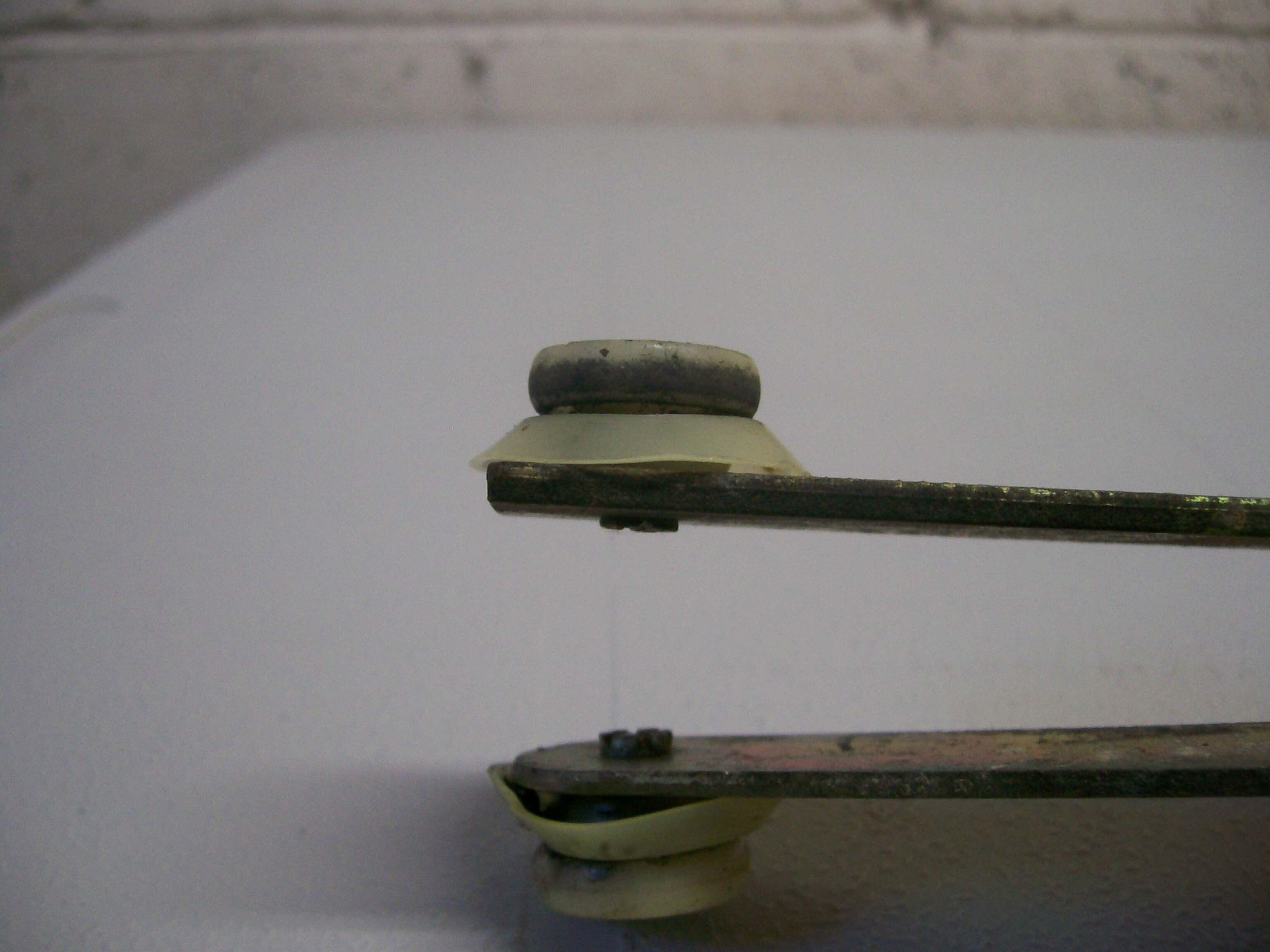
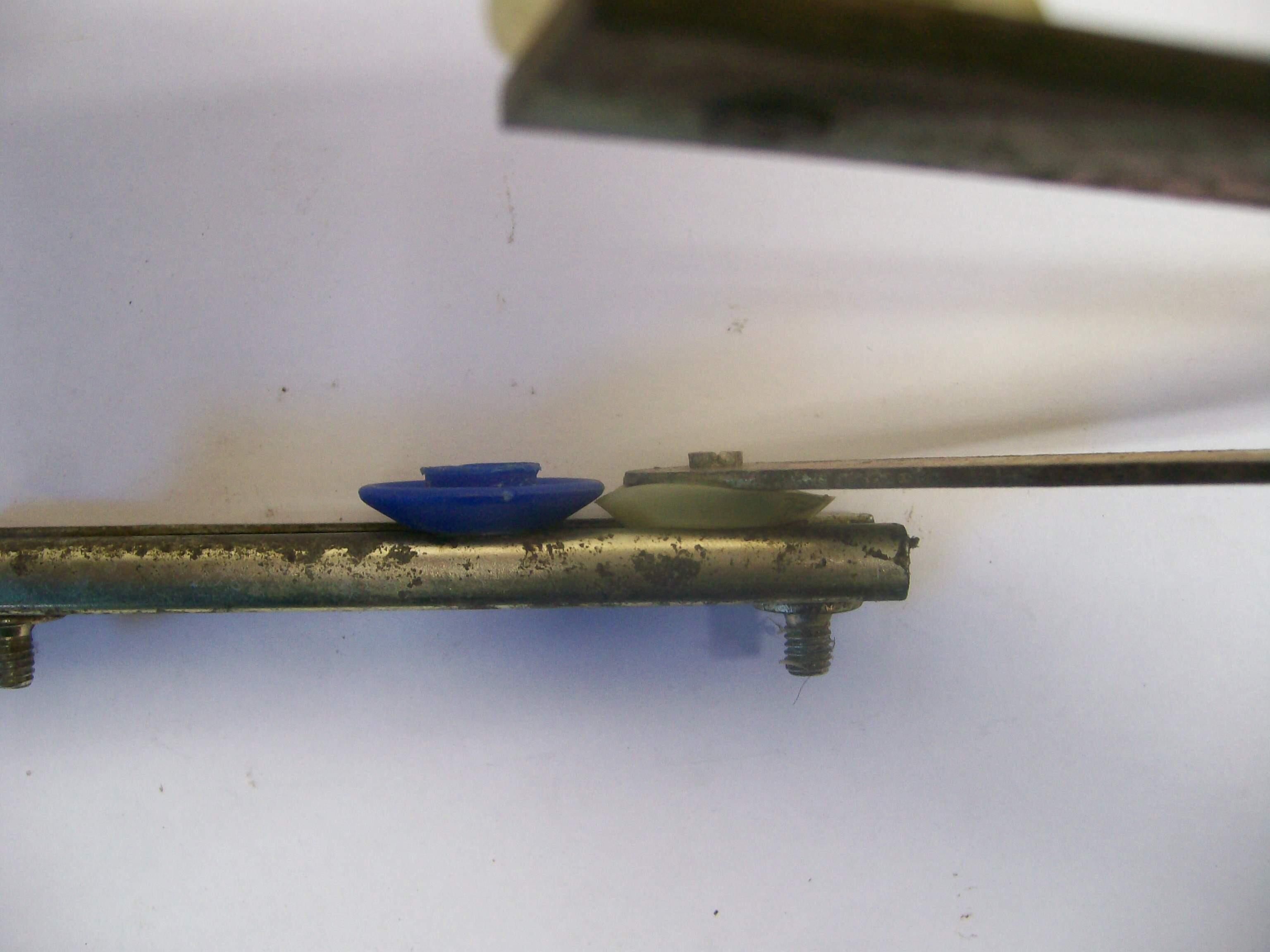
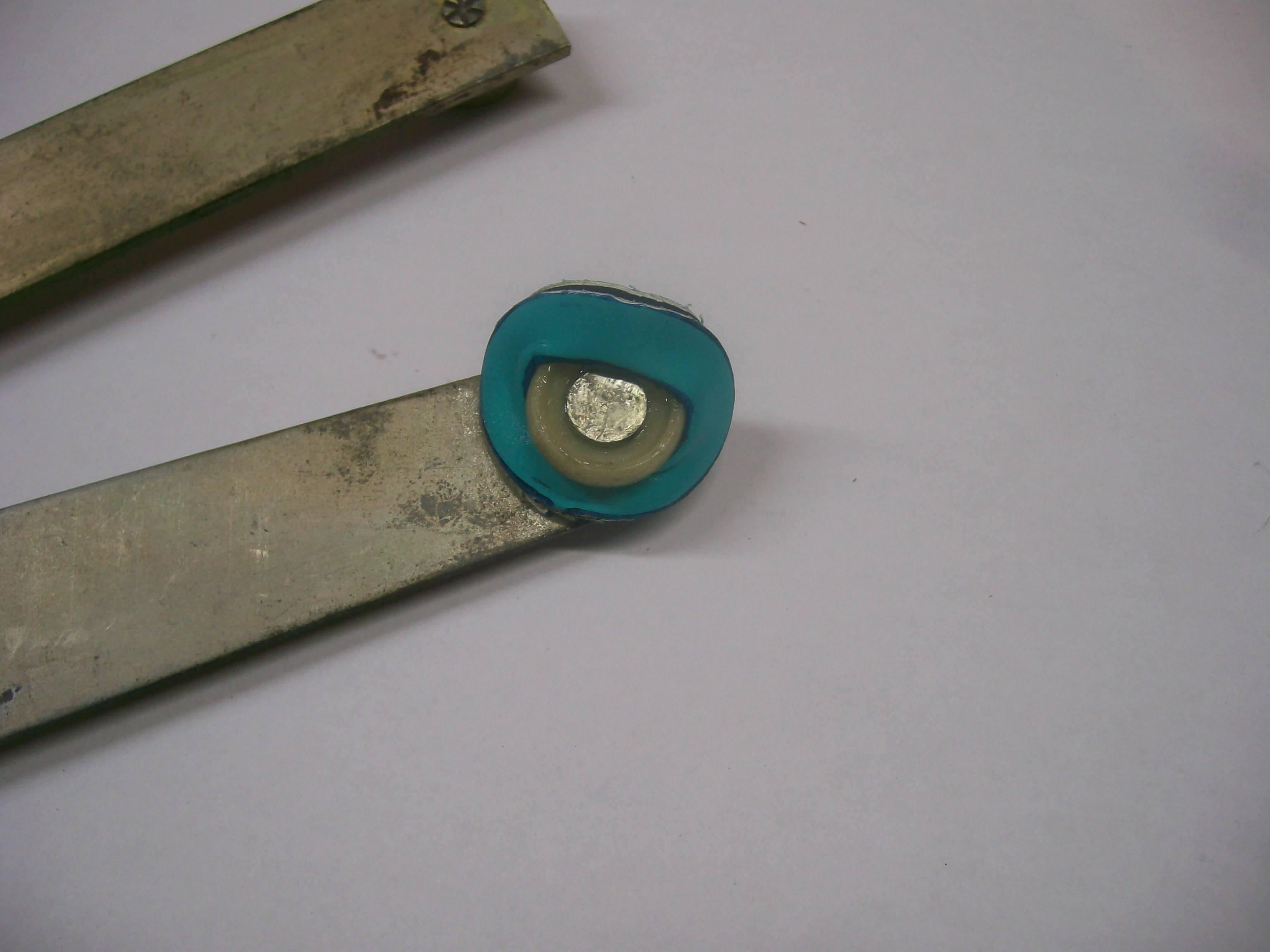
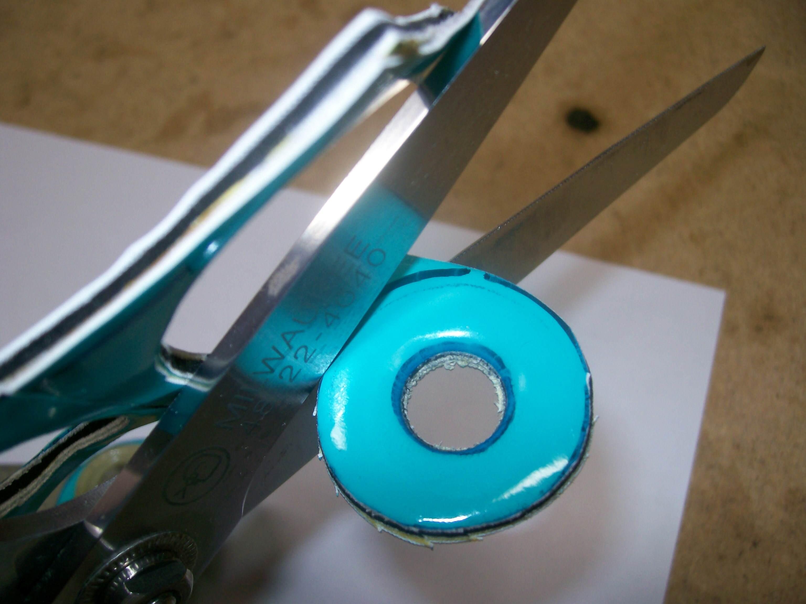
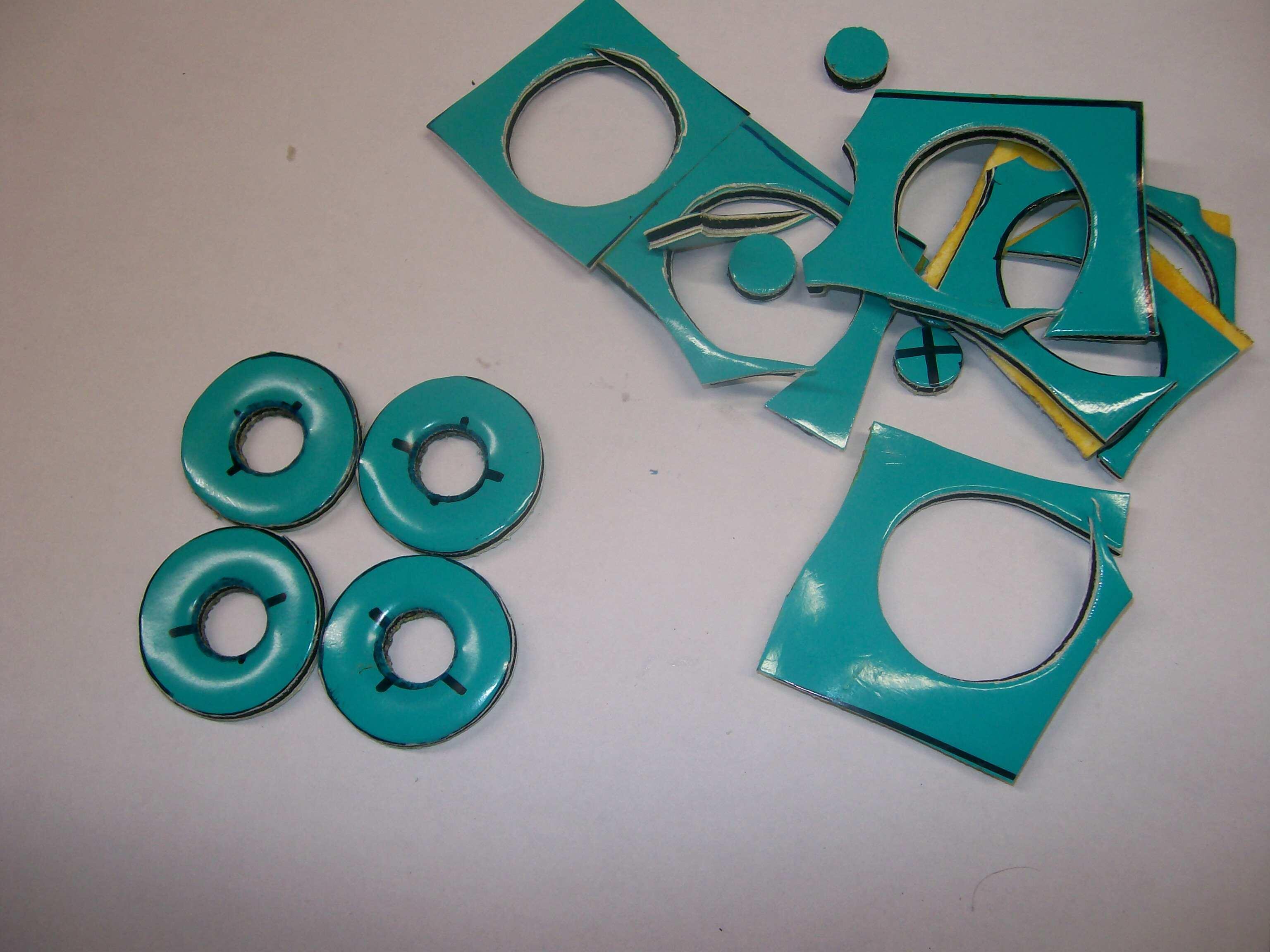
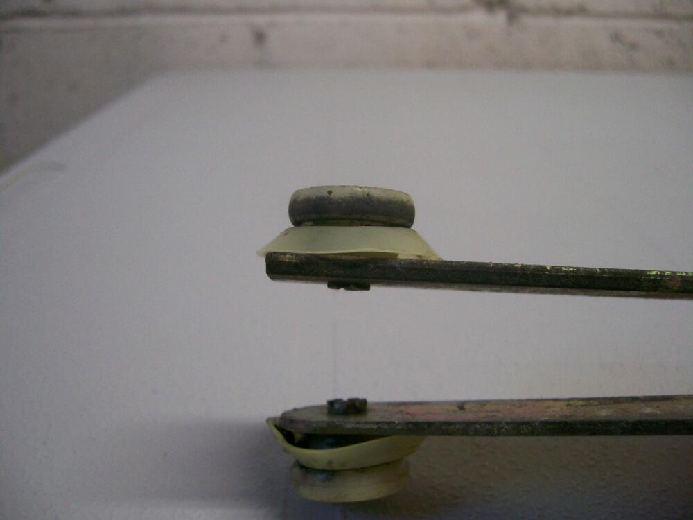
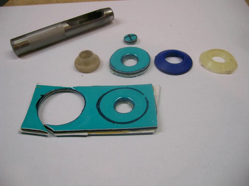
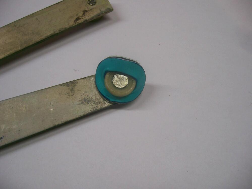
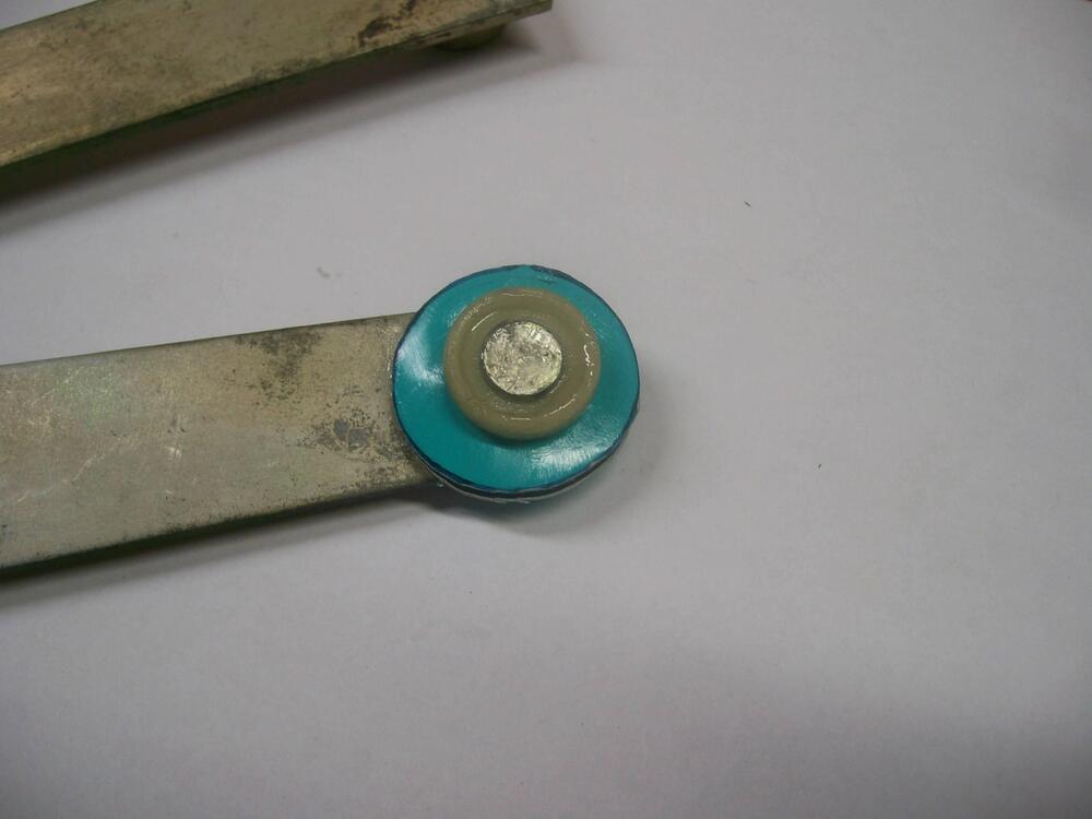
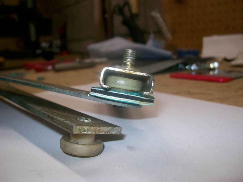
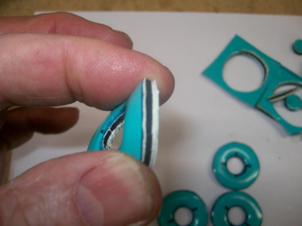
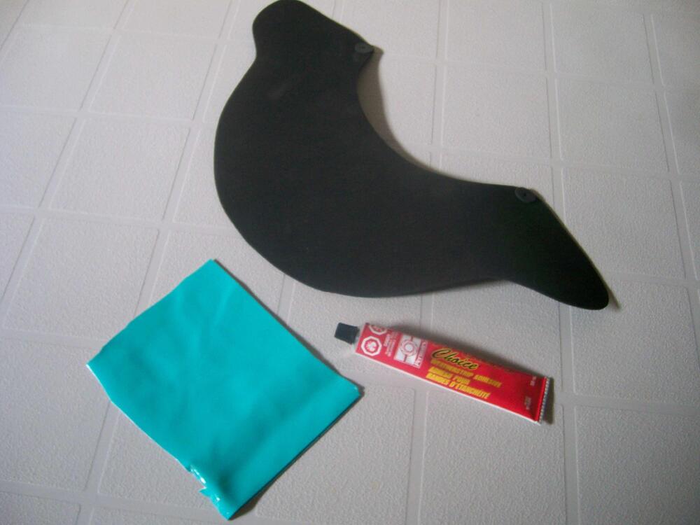
The rollers on my guides were fairly wobbly, so I decided that the flexible washers were providing not just a preload but also a self-steering effect for the rollers... The tarp grommets definitely take up the clearance slop, but they're not flexible... I decided to take a different approach. A search through my 'this may come in handy some day' box of materials produced a small sheet of nice, shiny, thin-and-flexible vinyl. I already had a sheet of closed-cell neoprene foam, ~ 3/32" thick, that I'd used earlier as a gasket material when restring my Z's heater. Using weatherstrip adhesive, I glued up a composite sheet with the vinyl on both faces and the neoprene as the core, ending up with something that was both stretchy and slippery... From there, I used a hole punch and scissors to create a set of washers... The new washers were stretchy enough that they could be pulled over the nylon roller... Once in place, they gave me what I was looking for...


-
My sense is that the cone shape is less important (perhaps unimportant) than the ID of the delivery tube. I suspect that the cone shape is provided to help prevent material from building up at the orifice exit. A thin-wall brass tube sleeve (see GK's message, above) will certainly give more strength to a solder repair, but it may prove to be a matter of winning the battle while losing the war. My 2 cents: Buy a new gun ($50). Annoying, but pragmatic.
-
Can't you just solder the two pieces together?
-
IIRC, it requires reaching up from underneath the car with exactly the right long-reach/thin/inflexible tool capable of snagging the release lever and budging it enough to pop the hood. Others, I'm sure, will be able to offer more details.
-
I like that description. One of the audible trademarks of a Z is the noise the doors make (clang!) when they're slammed shut. Some others that come to mind: Engine cooling fan that imitates a hovercraft Wheezy 'seatbelt not fastened' buzzer Sound made by hood release cable when it finally snaps
-
The Z uses 150 Hp to propel a 2500-lb vehicle. If you were to put that same engine in a contemporary mid-size SUV, you'd now be asking the same powerplant to propel a 5000-lb vehicle. The acceleration times would be cut in half. Also, you'd be dealing with a less flexible engine b/c of the absence of things like computer-controlled electronic fuel injection and cam timing. There's also the not-inconsiderable difference between having only 4 transmission ratios vs more contemporary units with 8 or more ratios and computer-controlled shifting. Doubling the vehicle weight certainly wouldn't be kind to the Z's clutch and gearbox (or engine). However, I have no doubt that they'd function ok... for a while. The Z's powertrain was a conservative design built with excellent materials. I think you'd be accelerating the physical wear on critical components by maybe 25% - 50% -- but not by 100%. Give it a try and let us know how things work out 😄
-
Maybe I've forgotten something about this procedure, but wouldn't it be easier to just remove the chrome retaining ring and pull the headlamp unit out from the front? Or perhaps you're referring to the procedure for a car whose headlights use replaceable bulbs rather than sealed-beams?
-
I wonder if this was intended as an alternate routing for the front wiring harness in cases where the car was equipped with an A/C condenser?
-
I didn't even know that those holes were wiring passthroughs, let alone the fact that they're supposed to be fitted with grommets 😶. My 240-Z learning experience continues.
-
Car looks great. Nice work, Chris.
-
-
Condolences to his family.
-
Sorry to be circling back to an earlier page in the thread. In your photo, how is the ratchet strap anchored where it disappears out of sight underneath the car?
-
When time permits, please explain your process for installing the hood (and bumpers) as a one-man job without damaging the paint. These pix are deceptive b/c they make it look easy (and I I know it isn't). Also: For everyone else, please take another look at GK's workspace. It's really not very big. The quality of his work deserves extra respect, given how challenging it can be to operate in a small space like that. I'm still amazed by how he managed to paint the car in that little garage. Too bad we don't have a video so that we could study how he managed the gun and the hose.
-
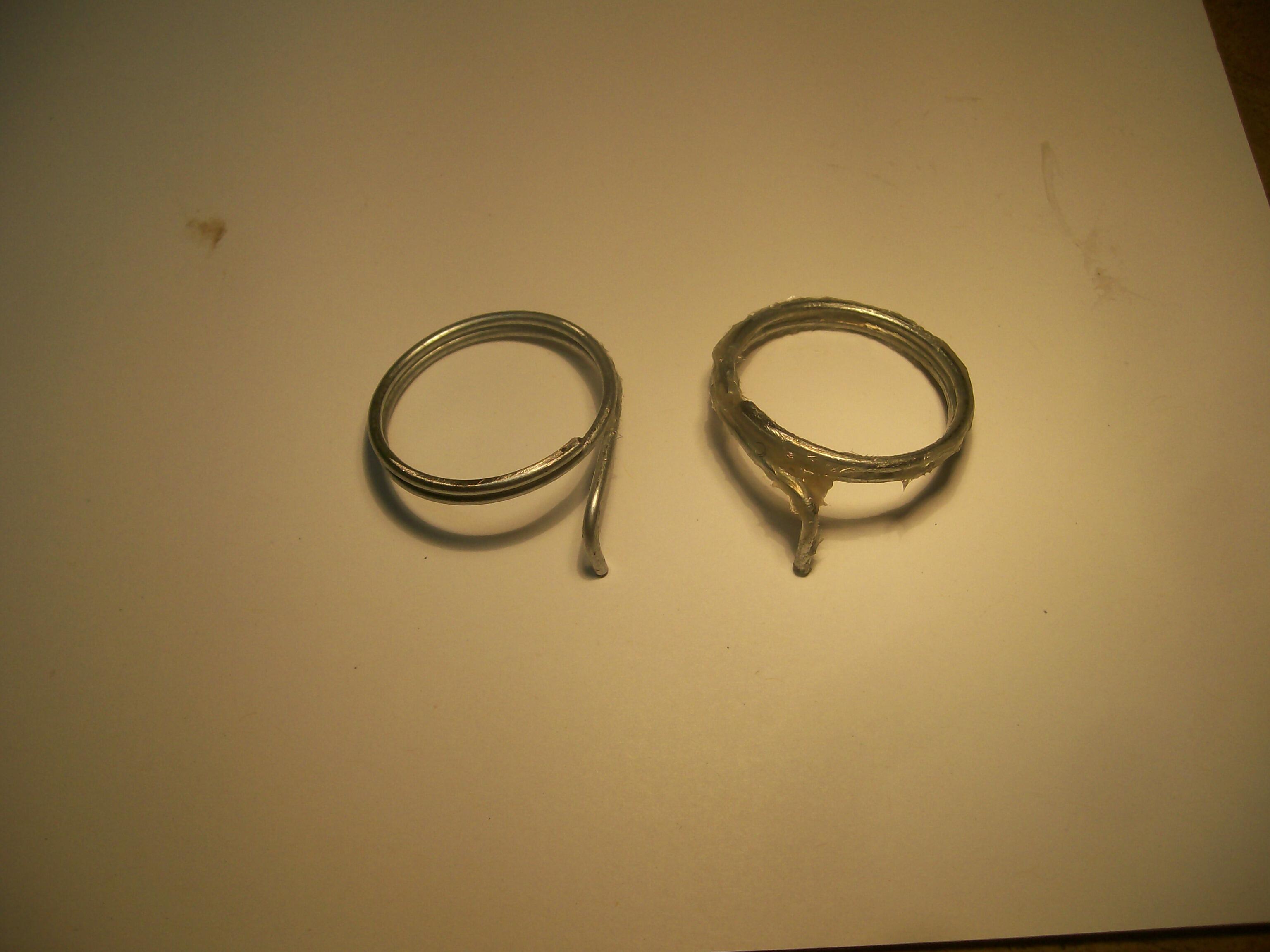
You're right. I'll edit my post. Here's a nice picture (credit unknown) showing the spring in its natural habitat...
-
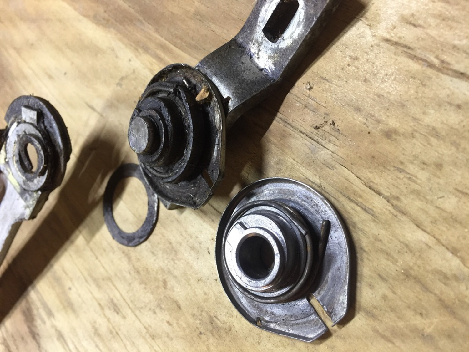
Good eye. I can't remember why I did that.
-
Although a bit finicky, but it's really not that hard to make a new spring from scratch. Start by finding a socket wrench with an OD that's roughly 75% of the OE spring. Clamp it vertically in a bench vise and then, using plain galvanized wire of ~ the same gauge as the OE spring, wind two turns around the socket. When relaxed, your coils will expand a bit. If the resulting OD is too big, you need to use a smaller socket (or vice versa). It takes a bit of trial-and-error. Fortunately, wire is cheap. Once you get the spring OD about right, cut it back to one coil, leaving enough to bend a 90-degree dogleg at one end. Cut the dogleg to length. Now heat your new spring with a torch to get it red hot and then quench it in a small jar of motor oil. Here's a pair of my homemade springs...

-
You might find this thread from back in 2017 to be of interest...
-
Great photo. One of the best I've seen to demonstrate what happens to cars like ours over the years as they're victimized by PO's and bodyshops.
-
For your possible interest, someone - Eastwood, I think, sells a 'comb' for straightening out heat exchanger fins.
-
Outstanding results! Now we're all waiting to see it trimmed out and sitting in the driveway in the sunshine.