beermanpete
Free Member
-
Joined
-
Last visited
Everything posted by beermanpete
-
 There is enough room for the 205/65-15 as long as the wheel offset is very close to 0. We have used up to 225/50-15 without clearance issues.
 -
You can put the washer/spacer at the bottom of the strut tube and avoid the need to increase the ID. It should take up the space just the same at the top or bottom of the strut.
-
Did you install the bump stops? Missing bump won't cause the suspension to be stiff but will cause a harsh feel when the car bottoms out. What springs do you have in the car?
-
It sounds like you could have way too much fuel. Float level too high, jetting way too rich, etc. Try disabling the fuel pump and run it until the float bowls get low on fuel. If it will idle for a short time before it runs out of fuel it is from too much fuel.
-
Confirmed. The only wheel alignment adjustment provided is front wheel toe.
-
Why nervous about using a Heli-Coil in cast iron? Cast iron machines and taps easily and the thread insert will hold as good at the original thread if it is installed correctly. It seems you want to weld in a stud but I am reasonably certain the factory stud is a threaded in. Welding cast iron is far more difficult that drilling and tapping it and can't be done correctly while on the car.
-
It sounds like the push-rods are adjusted incorrectly. When there is no free-play the master does not release fully and the symptoms you describe will occur. There are 2 push-rod adjustments to make. One is between the brake pedal and the booster. The other is between the booster and the master cylinder. When gently pushing the brake pedal by hand you should be able to detect two distinct free-plays that gets taken up as the parts start to touch. Once when the brake pedal push-rod touches the booster and another when the booster push-rod touches the master cylinder. The factory service manual shows the procedures. If you need the manual you can get a copy at XenonS30.
-
Use a Heli-Coil insert. They are available at most hardware stores and auto part stores. The "kit" comes with the correct drill, tap, insertion tool, and several inserts. When properly installed you will have new threads that are as strong or stronger than the original. Check the size of the existing hole to be sure the 3/8 kit will work. If not go to a 7/16 or M10 thread as appropriate. If you are careful you should be able to install the Heli-Coils with the manifold on the car. I suggest going back to studs and nuts when finished. It makes it easier to install the exhaust pipe.
-
:stupid: Ooops. I forgot that comression rod is the proper name for a part in the front suspension.
-
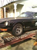
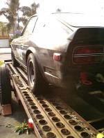
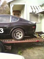
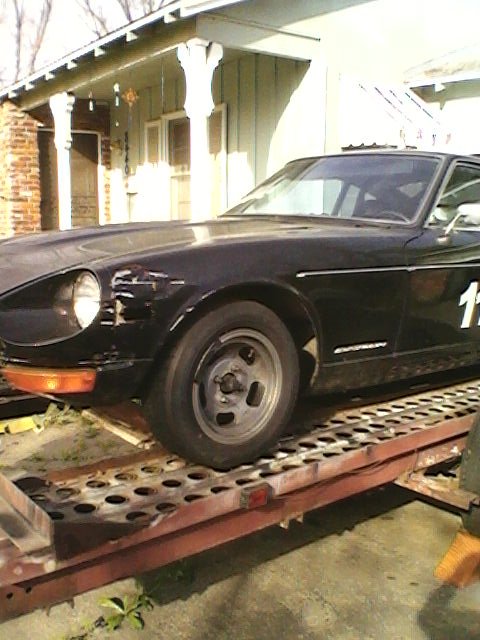
What are you planning to do with the car? For track use there are a lot of items that can go. Heater, A/C, wipers, bumpers, carpet, trim, and so on. The seats are heavy compared to racing seats. These can easily add up to 200 pounds.
-
If you mean the connection rod and wrist pin, the pins are a press fit with the rod. A press and suitable tooling are needed to remove them. You should take them to a suitable service shop for removal if you do not have the necessary tools.
-
The lock nuts for the valve adjustment can get very tight. I had to buy a longer wrench to get enough leverage to loosen mine the first time I adjusted the valves. If your wrench is not so long that it hits the strut tower when working on the #2 cylinder consider getting a longer wrench.
-
Looks like factory parts that were chrome plated.
-
The factory fuse is 20 amps (in the 73 at least). The fuse size really needs to be sized for the wire used as the fuse protects the wire from cathching fire if an overload should occur. What size wire are you using? Also, you should place the fuse on the battery side of the relay.
-
The voltage regulator will limit the system voltage to somewhere between 14.0 volts to 15.0 volts. At idle the alternator does not have full current capacity and might not be able to keep up with the electrical loads place on it. This is especially true when the headlight or heater are in use. In this case the voltage will fall a bit because the battery is providing the part of the current the alternator cannot. When the engine is running at higher RPM the alternator output rises and is more than required to power the loads. As the alternator output increases so does the battery voltage. This is when the regulator begins working and limits the voltage to the set voltage of 14 to 15 volts. In your case, 13.7 volts seems a bit low but is not necessarily a problem. The internally reglated alternators have a lower output voltage spec. Is it possible your car has been converted but the external regulator was not removed? Are you experiencing any problems such as non-starting or dim lights when driving?
-
^^Right^^ Also, the shifter has 2 seals as well (in addition to the dust boot). There is an o-ring around the striking rod guide and a seal around the striking rod (in the tail housing). While you are in there, check the vent. If it gets blocked it will cause leaks due to pressure build-up in the case.
-
14.9 to 15.1 is within the factory specifications for the externally regulated system.
-
Quick! Call the wambulance!
-
The factory coil is 1.5 to 1.7 ohms on the primary winding.
-
The coil design determines the need for a ballst resistor. If you are using a stock coil you need the ballast. Start by look at the factory service manual for the wiring diagram. If you don't have the manual it is available for free at XenonS30.
-
New SU parts are available here: SU Carburetters Home Page
-
The tach comes out toward the cockpit, not the firewall. Getting to the fasteners and wiring is a lesson in flexibility and clairvoyance. The dash cap will likely need to be removed first. I repaired my tach (4-wire type). There are 2 transistors that seem to get shaky with age. Search for info on the Smith meters used in English sports cars. The Z tach is a close copy. This link is to a schematic for the Smith tach. The Z 4-wire tach is essentially the same. Google Image Result for http://www.sw-em.com/1800_Smtihs_tach_schematic.gif Some of the websites discussing the Smith meters indicate the timing capacitor (C2) also ages and should be replaced. My complaint about the Z tach is that it bounces too much and takes too long to settle after a gear change. A small cap across the meter movement might help, I have not tried that however.
-
If you need a tach adapter it will be the 8920. There is instruction on the MSD website. Go here and enter 8920 to search for the instruction sheet: http://www.msdignition.com/instructiondownload.aspx The early Z has a current triggered tach, commonly refered to as a "4-wire tach" in the Z forums. It is true that if the tach were to become disconnected the car will not run. However, this is no more likely than the car not runnig from a bad connection elsewhere. Using the MSD igniton and tach adapter removes the tach from the primary circuit for the igniton and will prevent this particular problem.
-
The factory service manual reccomends setting the "high speed balance" at 1400 RPM. The balance screw for the high speed balance is in the throttle shaft between the carbs. The idle balance is set with the throttle stop screws (idle speed screws), one on each carb.
-
195/60R14 on 6" wide wheels. We have the Tokico lowering springs installed as well.