Everything posted by Patcon
-
sleeving master cylinders
Don't know on cost http://www.karpspb.com/sleeving.htm
-
sleeving master cylinders
I know many older more rare cars have very limited availability for parts. When they have a bad master cylinder, caliper or wheel cylinder there is no replacement available. So there are specialty restorers who can sleeve these with SS sleeves. Then new rubber seals and you're good to good for a very long time. I have a number of master cylinders that could be refurb'ed. Does anyone know of a source for small diameter SS sleeves?
-
Air Cleaner Won’t Clear Brake Bleeder Valve
That starts to make restoring and sleeving the old units I have laying around make sense
-
Tension rod mounts worn out - please help!
These should be the same on all S30 chassis's A donor is the best bet
-
Front strut casing and the steering knuckle will not come apart...
The knuckles have a milled area that fits up into the bottom of the strut They can be really difficult to separate. There is also a small O-ring that goes in there to keep water out of that joint. If you are just replacing the strut insert, it can be done without removing the strut from the car. If you really want to separate them, then it will have to be driven down with some force, which is going to stress the ball joints or you could try to drive a painters 5-way in between the parts.
-
Air Cleaner Won’t Clear Brake Bleeder Valve
Ouch!!!
-
Tension rod mounts worn out - please help!
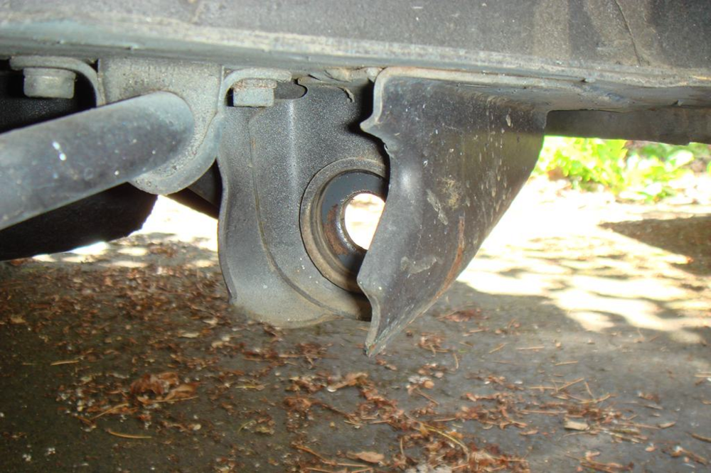
You are missing some metal there. There are some metal cups that are welded to each side of that mount that the bushings fit into
-
Clutch squeal when running
Good you figured it out.
-
Front strut casing and the steering knuckle will not come apart...
Can you post up a couple of pictures of what you have and the bolts you have removed
-
Picking up a 1977 280z 6 Hours Away. Tips?
Bayarea Don't get the idea to weld the roof joint up solid. The car needs to flex some and the designers selected this area to flex. If you make it too ridgid you could crack the A pillars or some other area on the car!
-
Cut Off Strut Tubes Wanted
I suspect the perches need to be indexed too. Just because it's "Obvious"...
-
Fuel tank is out, Any opportunities to do something else?
Make sure the chassis ground above the tank is clean and protected
-
Tips/tricks for removing windshield
You do have to be careful. I would bang or strike the glass. Firm even pressure and pull the cord. If you use too much pressure the cord can damage the seal. The dangerous areas are getting around the corners. Try to not stress or twist the windshield
-
72 Datsun 240Z Project Claptrap - Yes That Claptrap
Wondering why you want to make certain changes? Fuel cell? Push rod rear suspension? Tubular front end?
-
Trouble shooting
I'm glad you feel lighter now! I won't tell anybody
-
Incredibly Clean & Original 1973 240Z on BaT
Wow! That's strong
-
Calling all engineers
That's too bad
-
78 280z idle problem
S30 EFI is not my forte. I know enough to be dangerous. I know resistance and corrosion seem to cause 60+% of the issues we see come across the forum. The other portion seems to be component failure and PO's "fixes"
-
Advice for buying
Ohh...It's good to have dreams
-
78 280z idle problem
I understand, but they won't stay good for long. Better to do it once and not have to remember to come back and redo it later.
-
Dry/Wet compression #'s
If you are use to riding bikes, then yes, your calibration is way off. If the car sat for any period of time, then 2 cylinders could have been left at the bottom of the stroke for an extended period of time with the valves open. Some slight bore rusting would make those 2 cylinders measure low. I am too lazy right now to try to figure out if the crankshaft strokes correspond to your actual cylinder numbers. I would run it for a while 6 months to a year and see if the numbers don't even out some. For me, they are only slightly out of range. Being I shoot for all the numbers being within about 15%. 10% being even better, unless the motor is fresh
-
[2019] What Did You Do To/with Your Z Today?
That was my suspicion on the mileage being low. That's what made it seem odd to me that it needed replacement. Had it been bottomed out at any time?
-
Advice for buying
The lower front end parts are different on a 280z but with an airdam they look like a 240z. The bumpers are different and the tail lights and front turn signals are different. The rear tail lights are the only real difference if you try to make a 280z look like a 240z. I agree with Av8ferg above! Since your in an apartment then I would try to get the best 280z you can that actually runs and drives. Don't buy a car that "runs & drive" but hasn't been driven regularly. Many times people get these cars running again to sell, but they can have lots of problems that can be frustrating to diagnose. The S30 market is very hot right now, even for the 280z. If you find the right car you need to be prepared to go look at it and buy it if it's the right one. If you can reach out to some members local to the car or local to you would be a good way to get educated and help you sort cars. You can also post up cars her for us to critique
-
[2019] What Did You Do To/with Your Z Today?
How old are they? Any idea of cause?
-
Advice for buying
Everything! If you already have a donor, then I would go with the 240z or the least rusted Z you can find. You are way ahead of most people as you have a selection of spare parts. Do you live in an apartment? You don't need a shop or garage to do most of this work. If you have a driveway and your local government will leave you alone much of this could be done there, provided it won't get stolen.


 Subscriber


