superlen
Free Member
-
Joined
-
 My first thought on the plugs were that they looked pretty good too, but it's often hard to tell with a picture, and everyone's eye is calibrated a little differently anyway. I could easily be persuaded to slightly rich opinions. They certainly don't look far off. I'll add that the stock ECU does it's best to maintain proper AFR during warmup, but the design lacks great accuracy in this mode & would tend to run slightly rich during this period, purposely. Given that your actual CLT temp may/may not be at 180...the plug readings are a little suspect. +1 on what Captain said...ensure you actually are up to temp & verify your gauge isn't lying to you. You can then repeat the test, in theory with the exact same result, but you'll know for sure you were at temp, ? BTW, You may know this, but the stock ECU uses it's own sensor for CLT and does NOT share the same as what feeds the temp gauge, so don't get sidetracked thinking that the ECU was being fooled just because the gauge might have been reading too cold. Len
 -
Physically follow wire 72 from the FIR to where it is supposed to connect to ground. It should run to a ring terminal that is bolted to the frame someplace. I don't remember off hand exactly where it's at in the car. I seem to recall it coming through the firewall in the harness and terminated on the firewall, but don't hold me to that. It could be under the dash. I'll look at one of my test harnesses when I get home tonight and see if I can figure out more details. I have my car tucked away in a shed and can't get to it easily or I'd go find it and report back. The ring terminal will have several wires all coming together to get grounded at the same place. W72 may be broke, or cut on it's way to this ring terminal, or the ring terminal isn't connected, or it is connected but there is corrosion preventing a ground. I'm also going from memory that W72 does end up at a ring terminal and not through a connector or bullet type connector back to the battery. Regardless of the physical method, it has to reach a ground someplace. The harness does some internal splices that have been known to corrode. You can't see them unless you unwrap near the splice. Len
-
Great!!...you've found a major problem. W72 isn't grounded to the frame like it is supposed to be. There's no way the FIR can work without W72 making a connection to ground. Len
-
Good idea, Zed! Moozie, Remember we are testing that the pin/wire W72 right at the relay is properly grounded. There shouldn't be any voltage there ever! When you say "I'm not reading anything off of W72" it sounds like you're looking for voltage there. Maybe I'm interpreting wrong... The multimeter should be in volts mode, the Red lead on +12v battery, and the Black lead on W72. When connected this way, we are using the black lead to test if something is grounded. Anything you touch with the black lead that is ground should make the meter read +12v. Touch black to battery negative, read 12V, touch to car frame, read 12v, touch W72, read 12V. If the meter doesn't read 12V when it's connected this way then W72 is not grounded and your FIR won't operate as it has no ground reference. This would definitely be a problem! Note: You could also measure the resistance from W72 to ground, it should be 0 ohms (or very near). If you follow the wire (W72) from the FIR it should travel over to the frame somewhere and be grounded with a ring terminal along with some other wires. A visual inspection may turn up some corrosion at that connection or perhaps its just completely unconnected/broke/cut wire. I would take it loose and clean the ground connection even if it looks good just to be safe. Len
-
Well...we aren't making fast forward progress, but any information is good information. ? Q1) When you jumped 12v from the battery to W48 and you read voltage "in the cabin"..are you talking about the wires behind the passenger seat going to the fuel pump , or the wires under the dash near the relay, or someplace else? "In the cabin" doesn't help me any in debugging. If your fuel pump was still connected, 12V direct to W48 and you should hear it run. Q2) Did you confirm the gnd getting to the FIR as outlined in Test 5? If not, that would be my next step. We need to confirm if the relay connects W48 and W73 when the key is in 'START' position or the flap is open. As for the ECU short...if you shorted to W34 you're probably fine. You would see sparks as W34 is connected to gnd inside the ECU. I might recommend again to unplug the ECU before doing any of these tests. It doesn't need to be plugged in at all to diagnose the FI relay. It would not blow a fuse if you shorted 12V (that was directly connected to your battery) to W34. It would just be a dead short...there's no fuse in your connection. It could burn a trace on the ECU if left on long enough and with a good connection. I really doubt you did that so, don't worry. You can test by just hotwiring the fuel pump on and try to start the car. Len
-
Matthew , Buy a 280z and learn how to fix anything on it that breaks! It will be old, it will break a little. No worries, you'll work on it. You will fix it. You will learn stuff. At some point one of your friends "NEW" cars will break too...perhaps a waterpump leaking, or serpentine belt adjuster gets weak. You will know how to fix that too. Working on cars is a very important character building experience, and it hones your critical thinking/debugging skills tremendously. You don't need to know how to rebuild a transmission to get through life. However, experienced in diagnosing car problems translates into better diagnostic skills with every problem you will run into in the future. Your future success in life depends on buying a 280Z now! ? Feel free to show this to your parents. Len
-
I just noticed this thread and wanted to give you a thumbs up on persevering. I don't have much to add as others have been giving you great advice. You're close now. As Zed said once you start feeding the ECU a real coolant temperature sensor resistance instead of an open connection, the fueling will change, but then you can begin to figure out all the other things that have been modified on the engine in the past to compensate. I will add that the AFM position is rotated but shouldn't make a big difference. There is a weight on the flap that is affected by gravity, but the governing force in the device is the spring. The weight helps as a smoothing function on abrupt air speed changes and the momentum gives a bit of overtravel when you tap the throttle. The overtravel is by design to give a bit of extra fuel and is akin to the "accelerator pump" on a carburetor. Perhaps I should test the flow in two orientations to see if I can detect any change in the AFM output. I also have some spare harnesses that you are missing that you are welcome to if needed. Realistically, you can make one faster, and the ones I have are old and connections would need to be cleaned anyway. Still the offer is there, just pm me your address if you think they will help. Len
-
As others have posted, if the ultimate goal is *A* z, then you will be money and time ahead to start with a better donor. However, if you want to fix *this* Z, then I would recommend buying a welder and learning the bodywork. If you completely screw it up....oh well. It wasn't pristine to begin with & you will have learned some bodywork skills no matter how far you progress. If you are going to pay any professional to restore this particular Z, it's going to be pricey. If it has sentimental value, you're stuck.. ? We've all been there. I'll usually pay double for something rusty that I just think needs to be saved. Len
-
Ok, so no voltage there with flap open...so the FI relay is NOT routing 12V to this wire. Lets see if the relay is getting power to it.. If it doesn't get 12V fed to it properly, it can't pass it along to the fuel pump. (Note: I'm assuming that crank isn't giving you 12V either - you still should test that). -- snip from above Test 5 - Confirm that the FIR is getting a good ground. It is grounded by W72. Place the black lead of your meter on W72 directly at the relay and the red lead on a known good +12V and make sure you read +12V on the meter. If not, check W72 and find where it gets grounded. Make sure it's getting a good ground. Without the ground, the FI Relay has no chance of working. You can also put your meter in ohmeter mode and measure the resistance between W72 (again right at the FI Relay terminal) and Battery ground..Ideally it should be 0, but anything under 1ohm on your meter is ok. Len
-
W48 would indicate Wire 48. *Most* of the time wire 48 would end up a terminal on a connector and the connector will have '48' stamped in it, but this isn't always the case so it is a bit confusing. However, '48' is printed on the green wire...very small in faint yellow or white. ? It's best to work with the wiring diagram printed out in front of you and follow W48 to where it connects. W48 runs to the Air regulator as well as the fuel pump so do this: 1. Locate the two position plug on the air regulator. Note this is the auxillary air regulator, NOT the Airflow Meter (AFM). 2. Unplug it from the regulator. Forget about the regulator now. We don't care about it, it's just an easy place to find W48. 3. Look at the two wires going to the plug and find the one with 48 printed on it. 4. Take your voltmeter (make sure it's on Volts scale if multimeter). Black lead on bat ground., Red lead on Bat Pos. It should of course read 12V (just testing that your meter is working) 5. Now move the red lead to W48. It shouldn't read any volts. 6. Now turn the ignition key to crank. What does you meter read? It should read ~12V. (A helper is handy here) 7. Now take of the air intake boot in (front of AFM) so you can push your finger in their and push the flap open a bit. Read your meter again, it should read 12volts with the flap being pushed open, 0volts when flap is closed. Post back your voltage readings and we can keep tracking it down. Not the fastest of methods, but we can figure this out. Len
-
Here is a quick guide to how that FI relay works. First some notes: N1- The FI relay (FIR) actually has two physical relays in it (call them X1,X2). N2- X1 provides power to the fuel pump and the air regulator (both the pump and regulator +12V feed are connected together directly INSIDE the FI) When X1 fires, your pump should spin and your air regulator should have power. (remember this note for later when we debug the circuit) N3 - X2 provides power to the ECU, the Dropping Resistors, and the AFM air flow switch(which incidentally is also one of the items that can fire X1 to make your pump run) This is also the safety switch that if your engine dies, your fuel pump turns off. Caveat: 78 and later they replaced the airflow switch with an oil pressure switch. Both offer the same exact function, just a different method of determining when the engine is NOT running. N4 - X1 (which again will turn on your pump) gets it's signal and is fired by one of two methods. The AFM switch we just mentioned in Note3 & the start signal (CRANK) from the ignition switch. Either input will fire X1 and you should have a running fuel pump (as well as +12V feed to your air regulator) N5 - Datsun wiring harness for the EFI is fairly easy to traverse as Datsun conveniently printed the wire number in light white or light yellow numbers. If I refer to W36 it means the wire with number 36 written on it. Many times, but not in all case, when W36 terminates at a connector, the connector will have "36" stamped in it as well. For example, the AFM connector & the ECU connector. Somewhat UN-convenient is the fact that most all of the wires are green. ? -- Lets debug a little. 1 - If the pump isn't working, it can be one of the following: No power feeding X1, no signal telling X1 to turn on, or the power being routed through X1 is not reaching the pump. 2 - Remember Note2 where we said the air regulator and pump power are tied together. The air regulator is right on top of the engine and super easy to reach and test with a meter. So the first step is to pull the air regulator connector, locate W48. Probe it with a multimeter and see if it has power when you CRANK the engine and/or push the AFM flap in. If you get 12V there with either of those tests, you know X1 is working, and the problem is downstream of the FIR with the wiring from W74 exiting FIR to the pump, or the pump itself. 3 - If you don't get 12v with those tests, jumper 12v to W48 and you should hear the pump run. This will confirm your wiring to the pump is good and we are in fact chasing down a problem that is in the relay or power to the relay. IMPORTANT: The air regulator connector also has W34 which runs to the ECU. The ECU grounds this wire to turn on the air regulator. If you mistakenly jumper 12V to this wire you will be shorting 12v to gnd through the ECU!!! Don't guess, double check which wire you are working with. If you are worried, just unplug the ECU. 4 - If it is the relay, move on to ensuring that power is reaching the relay properly. This is a little more difficult as the relay isn't the easiest to get to. 5 - Before the next few tests, you need to confirm that the FIR is getting a good ground. It comes in on W72. Place the ground side of your meter on W72 at the relay and the pos side on the +12V and make sure you read +12V on the meter. If not, check the ground connection of W72. 6 - With the key OFF, measure voltage at W73 at the relay. It should be 12V. If not, check your fusible links. 7 - With the key OFF, measure voltage at W70 at the relay. It should be 12V. (The schematic shows direct from battery, but I believe it is coming from a fusible link as well) I'll confirm later.. 8 - With the key ON (but not cranking), measure voltage at W71 at the relay. It should be 12V. If not, check the ignition switch. 9 - With the key ON (but not cranking), measure voltage at W39/W10 or W43. All should be 12V. If not, X2 inside FIR isn't working.An easy way to reach W39 is at the AFM plug. 10 - With the key in the START position, we are back up to Step 2. Len
-
superlen changed their profile photo
-
Ron, I'll have to look at the schematics again and see where else that wire runs to. It sounds like you are on the path though. As for the HellFire, as Steve said it's a drop in replacement for the stock analog ECU. Unplug the stock ECU, plug in the Hellfire, hook up the laptop and you can look at every sensor, configure every table, adjust for any engine modification. Plug and Spray! Len
-
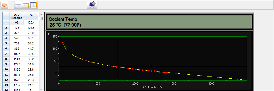
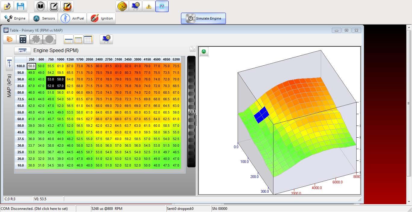
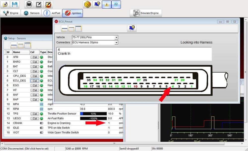
Another Update and a request for some critique/feedback. I have been working on two fronts lately, the ever time-consuming GUI and my flow bench to test/calibrate the AFMs. First, here are some screenshots of the GUI and I would like some feedback from users on what tools/features they typically like to see while tuning. Realize of course that the system ships as a 100% bone stock L-Jet replacement with ZERO tuning needed. However, the HellFire is highly configurable. You will be able run pretty much any combination of stock and aftermarket sensors. Stock AFM, with aftermarket analog TPS, Aftermarket MAF, stock cold start valve, or do away with it and have the ECU accomplish cold start enrichment, ect. Plus, even your "stock" AFM might have drifted or someone adjusted the spring and you may want to adjust for that in the ECU AFM table. Therefore, I assume that most will want to tweak a little even if they are running stock. At the very least, the GUI provides an awesome debug tool if you car isn't running right. The first is just a quick pic showing three of the screens. The main sensor view (kinda hidden by the ECU pinout help screen) & the pulse width view in the bottom right. The ECU pinout screen is interactive. When you mouse over the pins, the description field updates to tell you what the pin does. I abstracted this system so any number of connectors/pinouts can be accommodated with external bitmaps and text files. I only have three connectors currently, the ECU, the AFM, & the injector. Users could of course add any they liked as well. The sensor screen just shows the real time status of all the engine sensors which allows for nice troubleshooting. Also clicking the "CAL" button brings up the sensor calibration screen. The coolant sensor is shown below. It's updated realtime with crosshairs with data from the ECU. One question I had was for this screen. The table uses ADC counts (0-4096) vs output. But it dawns on me that ADC counts aren't as intuitive as just voltage at the ECU pin. So perhaps I should change this to make it more user friendly is someone is actually measuring voltages. The VE table shown is for Speed Density calculations. The 3d portion can be spun around using the mouse of course. The four cells that are being interpolated update realtime as you run the RPM and load up/down. Right clicking lets you do math on the table, smooth, interpolate, set a group of cells, ect. This is where I would like feedback too from users who have tuned some VE tables. I have no idea what is handy or just fluff as far as features here. I did add a jog dial (black vertical jog bar just to the right of the table) It allows you to tweak the active cell a bit at a time as you hone in on the value you like without constantly re-typing numbers. That's probably enough for this one post. I'll continue to pop in screens and ask for feedback if people are interested. Len


-
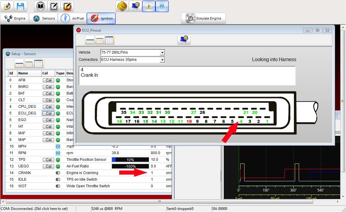
Ron, 10-4. As long as it's starting, take the Win! ? As a teaser, here is how I would check the crank signal using the HellFire ECU on my 77-280. (I added the two big red arrows in photoshop) Note: the help screen, too. You can't tell from the screenshot, but as you move the mouse over the ECU pins on the help screen, the description changes and tells you what each pin is. I still need to add into the program to show you the actual real time voltage being reported back from the ECU for each pin as you move around. The actual injector pulse width can be seen in the bottom right as the two yellow positive pulses (around 5ms each). This screen shot was taken in stock L-Jet mode so the ECU is batch firing two injector pulses/cycle. The second screen (added not because it has anything to do with the crank signal, but I just think it looks cool) is just a snapshot of the VE table as if you were running Speed Density instead of the stock AFM or an aftermarket MAF. Technically since the MAP sensor is on board, the VE table can always be calculated/interpolated even if you are running with the stock AFM. The reported grams/Sec from the stock AFM can then be compared to the VE table as a sanity check all the time. I haven't decided how to handle the case when the disagree with each other. I'll probably just make it a configurable item and let the user pick which one takes precedence. TPS is also available so there is actually a third Alpha-N table that can be thrown in the mix for even more redundancy if desired. Len


-
I just pulled my 75 FSM to look at the wiring. The relevant info is on page EF-47. Here is theory of operation (my words not FSM so anyone jump in if I don't make sense) 1 - Power to ignition switch through fusible link. 2 - Start position on ignition switch routes 12V to FI Relay(FIR) pin 86A. The wire leading there will be labeled 76. 3 - INSIDE the FIR pin 86A and 86 are tied together. So 12V will now be on pin 86 of the FIR as well. 4 - Connected to pin86 are two wires. Wire 47 and wire 4. W47 feeds the 12V crank signal to the high side of the Cold Start Valve (CSV). The low side is grounded by the themotime switch. W4 as we might guess routes power to pin4 on the ECU. W47 and W4 are spliced in the factory harness near the FIR & could very well be a source of your issue. Here is what I would check. - Measure the voltage at Pin/Wire 47 at the coldstart valve when you crank. This wire is super easy to get to & should be a solid connection to pin4 on the ECU. If it also reads 9.6V we can assume that splice is fine and the wiring from FIR pin 86 to the ECU is ok & we'll have to look some more. If it's 12V and the ECU PIN4 is only 9.6V, awesome!! We know where the problem is, it's the splice! These two points should be the same voltage all the time no matter what as they should be a direct connection. Len