


cgsheen1
Community Member
-
Joined
-
Last visited
-
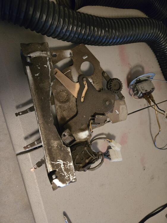
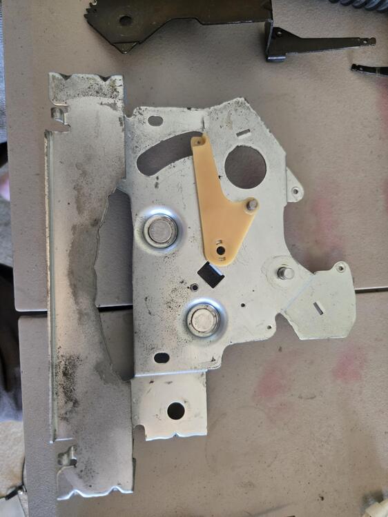
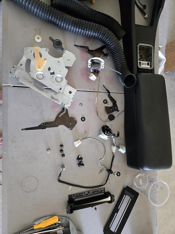
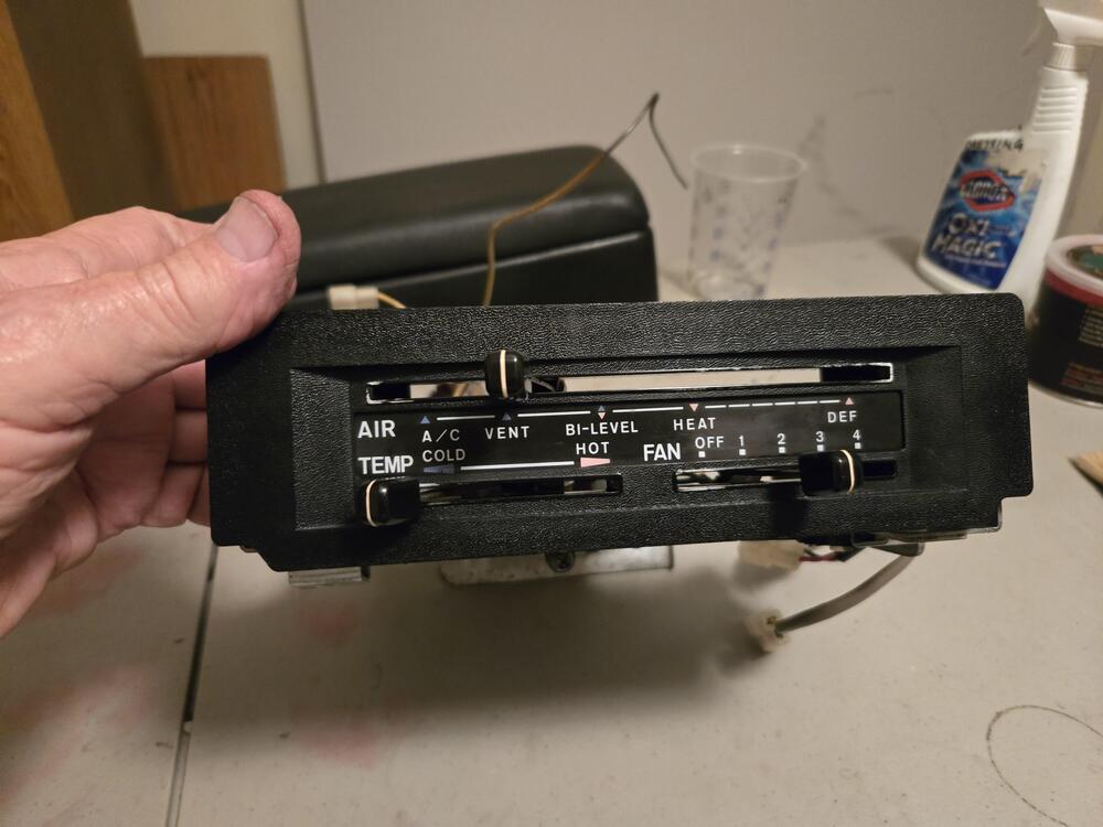
So after doing some extensive rewiring in Goldies front end and fuse panel I found my A/C compressor wasn't kicking on. In the search, I noticed a problem with the selector that prompted me to remove the HVAC control panel and below is the mung I found attached. I guess it hasn't been cleaned - ever. So I did. I used Meguiars Hyper Dressing as my cleaning solution and it worked well. I'd done one of these several years ago. I don't think it was quite this filthy. Everything cleaned up well and it all works as it should and it solved the issue with the A/C microswitch.


-
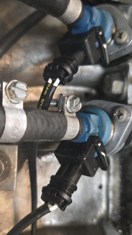
Vacuum ports on the crossover tube - no longer used. Consult the Factory Service Manual to see what their original purpose may have been. Maybe connections to the air pump.
-
I have no experience with the late 280 fuel tanks - only 1970-1976 - but on those the supply and return piping (tubing) is soldered to a plate which is soldered to the tank. I've repaired a few leaks on those (and the evap/vent hose fittings on those tanks which are also soldered on. I'm a Journeyman Plumber so I know torches, lead and soldering.) Although I've repaired leaks, I don't remember completely removing and/or reinstalling that tubing although those tanks are quite simple and I believe it can be done. Again, I have NO experience with the 1977-78. It, of course, requires removal of the tank and fuel and all the fuel vapors. I don't know what shop could get that done but Radiator Repair shops do a lot of soldering - though usually on brass...
-
Marvel Mystery Oil.
-
The front shoe has PLENTY of pad left on it. Does the rear shoe pad look the same? They don't always wear evenly. And was there an issue that prompted you to look at the rear shoes? Brake shoe friction material does not look like disc brake material and is no where near as thick. It doesn't have to be. There's no picture of the drum, but that shoe shouldn't have caused drum damage... Rear shoes aren't expensive, so while you've got them open I'd change them even though you don't need to. You probably don't need to replace springs either - but why not. OR, just button it back up and check again in a year or two. I daily drive my 260Z and have taken 3 or 4 runs a year with the guys where we go in the mountains and twisties and drive HARD. After EIGHT years of that - daily driving in Phoenix traffic and some hard stuff - I had to replace my rear shoes. Probably doesn't need to be done as often as you think...
-
So... How did you drive it with a seized fuel pump? Replace it? And, if you were driving it with old fuel, why are you now nervous about driving it with old fuel - with some added new fuel... L Series really don't like lean condition - don't mind rich at all. Are you really going to drive it half-a-tank at a time? The fuel tank will eventually have to be emptied and taken down and the intake tubing repaired or replaced if it really does have pinholes. Probably means rust inside the tank as well. Was the fuel pump seized due to rust or particulates? Rust in filter? The late 280 fuel tank is different than the early Z's and should be able to be inspected from the "top port" for the fuel gauge sender mechanism - once the fuel tank is emptied. I would suggest you have someone do this for you - that can also get a camera down in there.
-
Did the engine need work when you parked it twelve years ago? The oil system doesn't become "un-primed"... You basically have the option of having the engine pulled and "rebuilt" before it's ever turned over again or change the oil (add a quart of Marvel Mystery Oil when you do) and roll it over. Sitting for 12 years doesn't necessarily mean engine gone bad (realize I'm speaking as a (dry as a bone) Arizonan and not a Pacific Northwesterner). The L Series internals are stout. Your concern should probably be more focused on carbs, fuel delivery, cooling. Find someone who knows SU carburetors inside and out. If you can, the rest of the engine is a piece of cake for them more than likely. Look at the CAM, if it's clean and lobes are shiny, chances are the bottom end will look nice too. This is just me, but if the engine was working fine, running great, no problems when I shut it down, I wouldn't tear it apart. I'd just make sure all the peripherals were working properly and get it running again. Get rid of the bad gas, rust in the fuel system, same with the coolant, check all the hoses and rubber (oh, wait, you're NOT in Arizona!). (Speaking of which - here in Phoenix - a total L-Series engine rebuild (even if you had to get pistons and rings made), fuel tank cleaned, hoses replaced, radiator replaced, carbs rebuilt, alternator replaced, starter replaced, (what else am I missing...) WOULDN'T cost $10,000. And half that would be a rip - unless they repainted the engine block the correct Datsun Blue...
-
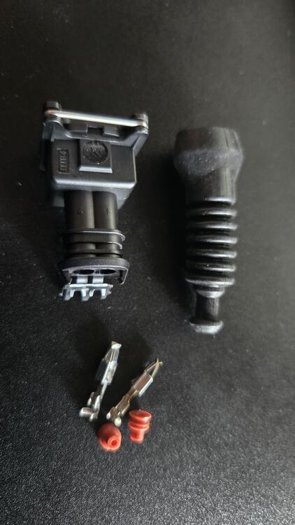
I used the connectors with the boot when I built my first Megasquirt engine harness. The boots cracked and failed after a few years. This is Arizona, and I daily drive even in the heat, but I was still disappointed. The harness I recently built for my AEM Infinity ECU I used the connectors with no boot. I have connectors similar to conedodger's that have a "rubber" cap boot with 2 holes for the wires. It's much more compact than the boot below but the "rubber" is questionable. After my last experience I wish I could find an Old School German or American made boot - maybe silicone... This is the type of boot that failed me. There are several different types of Bosch connectors - these are weathertight without the boots.
-
I don't have a vacuum bottle or solenoids in my Z. I could have sourced them over the years, I may even have everything stuck in a cabinet somewhere. BUT, all I've ever been interested in is the A/C - SO I've never bothered with it OR the vacuum lines or solenoids under the dash because the HVAC system defaults to typical Air Conditioning settings: Air out the dash vents and cabin air recirc - not fresh. I'm an Idaho boy so Arizona never really gets cold enough for me to use the heater - good thing because my core leaked nearly as soon as I had this back on the road 13 years ago. I've never bothered replacing it. BUT, there's an excellent description of all the vacuum line connections to the distribution block and how each mode functions in the FSM. It's in the Air Conditioning section - if you don't have A/C just ignore those parts - the heat and defrost and recirc and fresh air, bi-level, mode doors, solenoid operation is all in there.
-
The Wiper Amp has two sets of pins for 2 different connectors. It also has plastic "risers" next to the male spades to prevent you from inserting the wire connector improperly. One side of the female connector is thinner than the other. The thin side goes against the plastic riser. You're not supposed to be able to connect it the other way but ... I just had my wiring harness apart in that area and had to reconnect all the relays and etc.
-
Yup, 12. There's a door closer to the firewall that is heat to the cabin - pretty much right in front of the defrost port. It flaps up and down - well swings from closed to partially open anyway (on the 240 it's controlled by a cable - I don't remember on the 260/280...). Warm air on your feet... I have a blower box in the garage. I'll see if I can pull it out and get a pic or two. I think maybe closing that might be what diverts air to the defrost.
-
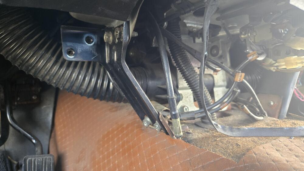
I have my center console out right now but this shows the defrost hose as it attaches to the blower housing in the 260/280. The 240's are similar. My hose is not original. Okay, I'll do the dusting before I put the console back in... The blower end of that hose is basically just above the transmission tunnel and at the rear end of the blower box - which means it's almost to the center console front. That's fairly easy to see once you get down on the floor. Everything is a bit crowded on that side of the dash but once upside down under the dash you should be able to see or feel it all. The hose isn't very long and it goes straight up into the plastic "diffuser" piece. If it was disconnected from the blower housing you'd probably see it hanging loose near your calf as you sat in the car - and you'd feel the defrost air blowing sideways into your leg.
-
Here's why I mentioned the non-standard Nissan Sealed Beam connector wiring. They essentially wire it backwards (because they want the switch to control negative rather than positive) - Hot to the standard ground connector, then Ground(s) to what would normally be the "+" side of the low & high beam filaments. The dimmer switch controls the "direction" of the ground from High to Low Filament. It might be interesting to disconnect the headlamps temporarily and see if that has an effect on the turn signal function. I installed some (Amazon) Halo LED Headlamps for a young man's 240Z here in the Phoenix area several months ago and they required changing the Nissan wiring scheme to the "standard" sealed beam plug wiring. I was wondering why yours just plugged in - and worked...
-
-
Only in the rear? (oh, paid attention to the video, so never mind... In the sequential mode the flasher must be ignored - so those lights require a constant positive source for controller and lights.) The Z will have a ground to frame connection in the rear - Wire with eyelet bolted to the sheet metal on the right side I think. But most of the wiring back there including the fuel pump should use that ground I believe... I still don't see why any of that would cause the problem. Zed Head has a point. Many of the new controllers use 3.3 to 5 volts (most 3.3) and generally are tolerant of higher voltage only up to a certain point. But that wouldn't explain why it behaves normally everywhere but the left side. Both voltage and ground hit the back on the right side of the chassis and travel to the left - meaning that is how the harness is laid out - It starts in back of the glove box -> passenger floor right side -> into the right quarter panel and over the wheel well -> along side the evap tank and fuel filler -> to the right side tail lights -> license plate lighting -> left side lighting -> radio speaker and antenna. As he said, a hank of wire to temporarily provide a new ground straight from the battery to the light - good test. If not that, logic dictates that the only change between connecting it to the right side and left side would be the wiring between the two... And you're aware that there are two separate flasher units - one for the turn signals, a different one for the emergency flashers. Weird problem...


