cgsheen1
Free Member
-
Joined
-
Last visited
Everything posted by cgsheen1
-
 There is no "play" there when the engine is turning. The play you have there is only because the cam isn't in a spot where it's resisting the crankshaft motion. Roll the crank a bit clockwise and it'll tighten right up. Then check for chain stretch as per the FSM and linked above. But, if you're that far into the engine already, replace the entire timing set. When the engine is running the tensioner isn't just using the little spring inside it - it's using oil pressure to keep tension on the chain. You can't really mimic that with the engine apart and there's really no need to.
 -
The Fuel Pressure Regulator is supposed to maintain a fuel pressure differential of 2.5 Bar (~36.3PSI) between the fuel rail and Intake Manifold Pressure. So on a running EFI engine, fuel pressure is not a static value - it (constantly) changes with manifold pressure. If you have 10 PSI of vacuum, the FPR is going to pull 10 pounds of fuel pressure. Likewise if you're making 10 pounds of boost it's going to add 10 pounds of fuel pressure. To verify the correct fuel pressure on a running engine you need to know the value of both fuel rail pressure and MAP (manifold absolute pressure) at the same moment in time. The fuel damper is installed to smooth the output of the stock fuel pump which squirts fuel in pulses rather than a steady even flow. Injectors work better with a steady even flow. Must be a little important, and nearly every modern EFI car has one too (probably much more critical with todays emissions engines than it was back in the day). That's if it's still working properly after 40+ years... The stock FPR held fuel pressure even when the engine shuts down, so the fuel pump must also check fuel flow back to the tank. I've noticed that most aftermarket FPR's don't, and that also includes most adjustable FPR's. Did you ever say why you think your fuel pressure is a problem?
-
-
No one, I hope... Just me, but I really don't like the 280 "bulb" valence with the 240 style bumper - screws with the line of the headlight bucket. To my eye, the bumper above is also too "high and tight". It accentuates the bucket / valence offset rather than minimizing it if it were a bit lower and protruded a bit farther. Well,,, You asked!
-
Easy way to check the gauge itself is to ground that YELLOW wire with the ignition on. It should peg the gauge to F. You don't need to let it go that far, if the needle moves the gauge is good. The wiring and fuel level sender are easiest to check with a multimeter reading the Ohms value between the two contacts on the sender. You can do that at the sender itself, at the connector under the hatch, and at the yellow wire going to the gauge in the dash. The fuel level sender is a "variable resistor" (and built like a rheostat) - it's resistance value changes with the level of the float. As long as you can read a resistance value (ohms) between the yellow wire and ground (black wire) the fuel level sender is probably okay. (the gauge is expecting a certain range of resistance between empty and full so that could be an issue) IF the gauge is good then you need to check the sender and the wire path between the sender and the gauge.
-
From the web: Place the 1-quart container in a well ventilated area. Pour the oleic acid into the container. If pure oleic acid is unavailable, Murphy’s Oil Soap may be used a substitute, as it is essentially the same substance, and works well as an ingredient in clock movement cleaning solution. Add the acetone to the oleic acid. Slowly pour the ammonium hydroxide into the mixture of oleic acid and acetone. Do not pour too quickly, or the mixture will splatter. Ammonium hydroxide, 26 degree Baume, is a common, commercially available preparation of ammonia. The 26 degree Baume refers to the strength of the solution, and is equal to a solution that contains roughly 30 percent ammonia by weight. Let the mixture stand for a few moments after adding the ammonium hydroxide. Clumps of soap-like material will begin to appear on the surface of the mixture. Lightly cover the opening of the 1-quart container. Do not seal it airtight. Leave the mixture in the container for about two hours, or until the clumps have completely settled out into the mixture. Pour one gallon of water into the large container. Add the contents of the 1-quart container to the large container to form the clock movement cleaning solution. Things You'll Need: 1 quart container 4 ounces oleic acid 8 ounces acetone 12 ounces ammonium hydroxide solution, 26 degree Baume Large container – 5 quarts or more 1 gallon water Tip If using the clock movement cleaning solution in connection with an ultrasonic cleaner, dilute the finished solution with an additional one quart of water. If making larger or smaller amounts of clock movement cleaning solution, increase or reduce the ingredients proportionally. Warnings: Wear rubber gloves when working with ammonium hydroxide. Avoid breathing in the fumes. Simple, ya? Actually there are pre-made clock cleaning solutions available and most people also use an ultrasonic cleaner. That works for cleaning the movement parts if they haven't been damaged and/or not excessively worn.
-
Ya, you could run a jumper from battery to flasher - but you're bypassing the fuse. I wouldn't. I don't know anything about the electronic flashers but from it's description, I don't know why it wouldn't work. Other people use them. But, is there a specific way they have to be wired? Is one pin dedicated to voltage INPUT and one to voltage OUT? NM, I just saw that the "X" terminal is for the GREEN wire and the "L" is for the WHITE wire... Look, the hazards work, yes? Then the issue is somewhere between the fuse and where the turn signal switch connects to the dash harness. Stop wondering about everything else. You need a dual filament bulb in the 240Z Park/Turn Signal housing. It has to be a dual purpose bulb. (If it works with the hazard switch, it'll work with the turn signal switch)
-
The Hazards and the Turn Signals work on two different power sources (because the Hazards work any time and the Turn Signals only when the ignition is in the ON position...) Power (battery voltage) for the Flashers: Battery -> Ignition Switch -> B/W to Fuse Box -> F (flasher) Fuse Box terminal -> Green wire to Hazard Switch -> G wire to Turn Signal Flasher unit under steering column -> White from Turn Signal Flasher unit -> bullet connector Green wire to Turn Signal Switch. The green wire on the switch is connected to the center of a "tetter totter" inside the switch. When the lever is in the middle (off) position, neither side "touches the ground" and no voltage travels through the switch. When the lever is moved, it pushes one side or the other down to make contact with two "points, or contacts" that deliver voltage to two wires - one takes power to the front turn signal bulb, the other to the rear turn signal bulb. That's true of both the right and left sides. The flasher unit (not a relay) works using a wire wound around a bimetal arm that "makes" and "breaks" the circuit as the bi-metal heats (and bends) and cools (and straightens). It uses a "resistor wire" that heats up as current goes through. It does so fairly quickly giving you the familiar "blinking" light feature. That's the old-skool way. An electronic flasher does it with a solid state timer circuit and accomplishes the same effect. The same Green wire from the "F" fuse terminal also powers many of the gauges I believe. Have you tried removing the flasher unit and "jumping" the green and white wires together? That should just remove the flashing effect and light the turn signal bulbs solid while you have the switch in the right or left positions. To eliminate the hazard switch as a possible problem, just unplug it and jumper the two green wires together. The wiring that goes out to the bulbs all ties together in the dash harness - the turn signal and hazard switches use the same wiring and connectors within the dash harness(es) so... If the hazards work, the wire and connectors (dash to engine harness & dash to body harness) all must be intact so you're looking in the right places - switches, flasher, associated wiring and connectors.

-
-
I am the bubble. I am the bubble. I am the bubble... Nope. Didn't help. I guess I'm just not Zen enough. 😝
-
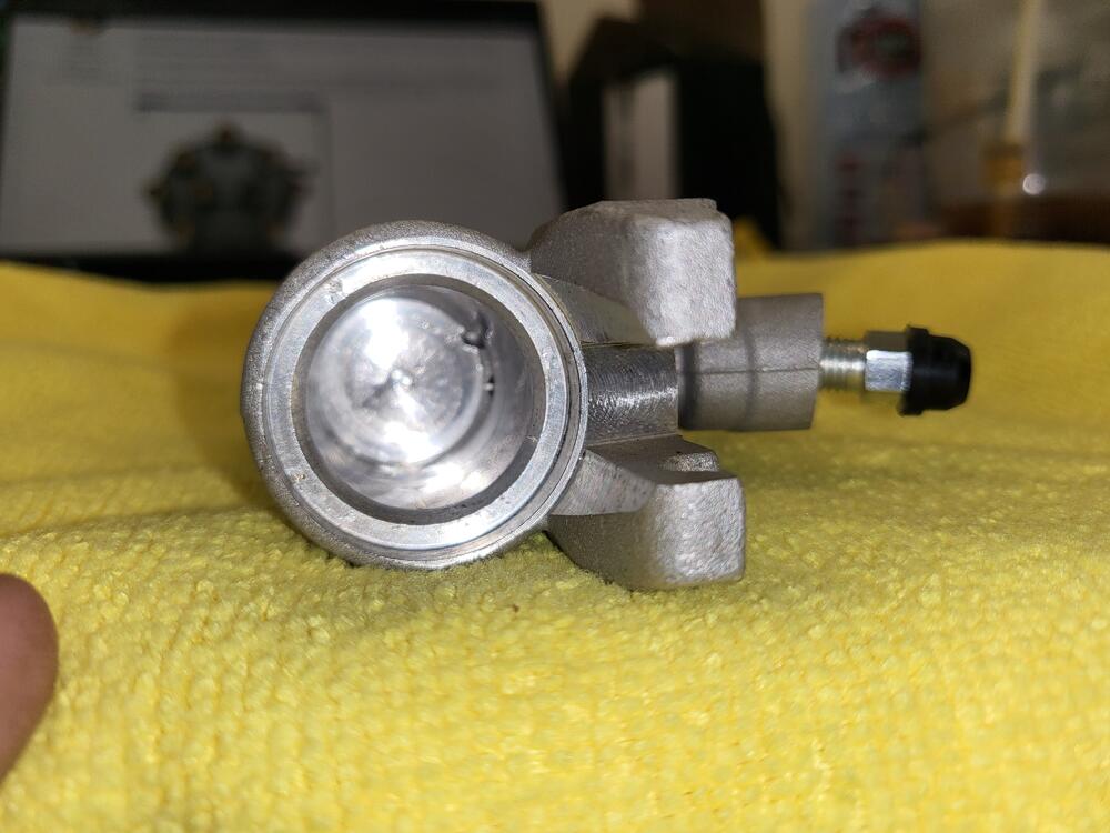
So, here it is. The bleeder is tapped and drilled at an angle. It enters the wheel cylinder NEAR the top... The brake line feed is drilled perpendicular and enters at the center of the cylinder. I think Cap has it with his excellent Fluid Dynamics instruction.
-
Tomorrow I'll be replacing rear cylinders - discovered that my left rear was leaking yesterday. Two new rear cylinders are being delivered to the shop in the morning... While I don't know if the bleeder comes off the top top, I think it's an optical illusion to believe it's on the bottom and there are cavities inside that could retain air during the bleed process. That goes against everything humans building cars have known about hydraulics for the past 100 years.
-
Is it though? Or does it just seem that way? Never-the-less, people have been bleeding these successfully for 50 years. I use a slightly different bleed method than most. I bleed the master first (in car, using the bench bleed method), then the left front, right front, right rear, and left rear. It doesn't take more than 3 pedal pumps to bleed each corner this way. My bleed hose goes up - above each bleeder valve.
-
Just as an FYI: Transmission Parts Distributors has the same kit with free shipping. Ends up a little less expensive even than Rock Auto.
-
The stops were just to keep the nose of the hood from hitting the steel bumpers on the lates. I don't think there was ever an issue with early Z bumpers that required a stop to limit travel. The difference in the hinges was just a small piece of metal welded to one of the arms to halt motion at a set point. I'd use hinges without stops if you have them, it'll keep you from hunching over so much...
-
Ya. And that's become our business...
-
Q, Take that hatch off and don't put it back in until you have the glass and trim installed. Seriously. You may think it's better to fit and adjust with the glass removed, it's not. Adding right side struts are a very good idea for a 240Z, but I'll be very surprised if that's the answer to your issue. I'd look at the hinges again, angle of the hinge mount to the body, or angle of the flanges on the hatch itself. Have the welds broken on the hatch flanges on either side - or have they been re-welded at some point? (That issue came up not long ago at the shop...) I would want the actual hinge (the point that rotates) to come up in the cavity - which would mean rolling the top of the bracket rearward and the bottom of the bracket close to the body (shimming the top, keeping the bottom flush against the body)). My hinges have never been off the body - the "pin" is so far up in the cavity such that I can't reach it with my finger. The front arch of my hatch is like yours, it's "more flat" than the roof arch so when it's coming up the center of the hatch is closer to the body line than the corners... I have a pretty consistent ~6mm gap at the top of the hatch, 5mm gap on each side (slightly wider at the bottom on the right side), and mine juts past the quarter sheet metal about a millimeter on the left and maybe 1.5-2mm on the right. (I could probably remove shims and get a tighter match at the rear and still clear the body but that's just too damn much work for a 70 year old...). I'll see if I can get an angle measurement on the hatch flanges when I get to the shop tomorrow. Keep a couple layers of tape on the body and the struts off or completely out of the way until you have the hatch aligned - it's a two man job. (we use microfiber towels draped over any crucial body area until we're sure there isn't any contact point whenever we do hatches or hoods and/or keep all the edges covered with 3M Blue Masking Tape. Two men - watching each side, corner, and top gap as we move it up and down.
-
I was wondering the same thing Racer. My Toyota calipers have way more rotor (Z31 vented) clearance than he's showing there. Are those calipers S12/W ?
-
Agree. The stock R200 in a manual transmission, non 2+2, would be a 3.545 which should use the black speedo pinion gear. Your transmission is early, but even the ZX transmission would use the black pinion gear.
-
Firstly, you never lift a Z using the frame rails under the floors - even if they were brand new. Secondly, Whenever possible use Granny's advice and lift the front using that big plate in the center of the front crossmember. Thirdly, When using a floor jack (not a scissor jack, not a bottle jack), we lift the differential in the rear and then place jack stands. There are a few "hard points" in the rear to help. Fourthly, The 280's added a lot more heft to the unibody and were strengthened in specific spots underneath (meaning: there are big beefy steel plates under there that the earlier Z's either didn't have - or were not as strong). You should learn those spots, they will help with lifting and supporting if you need to work underneath. Fifthly, be absolutely certain of your jack stands if you're working to replace the transmission fluid. In most cases both the fill plug and drain plug have been over-tightened and many people have struggled to get them loose. That means you're putting a lot of torque into it, may having to use a "cheater" for leverage - you don't want the Z to come down on you while you're under there. Sixthly, When you put the plugs back in, don't over-tighten them! There is no pressure on the fluid inside. Use Teflon tape (or anti-seize) on the threads and only tighten them to snug. You just want them just tight enough so that they don't leak - and done.
-
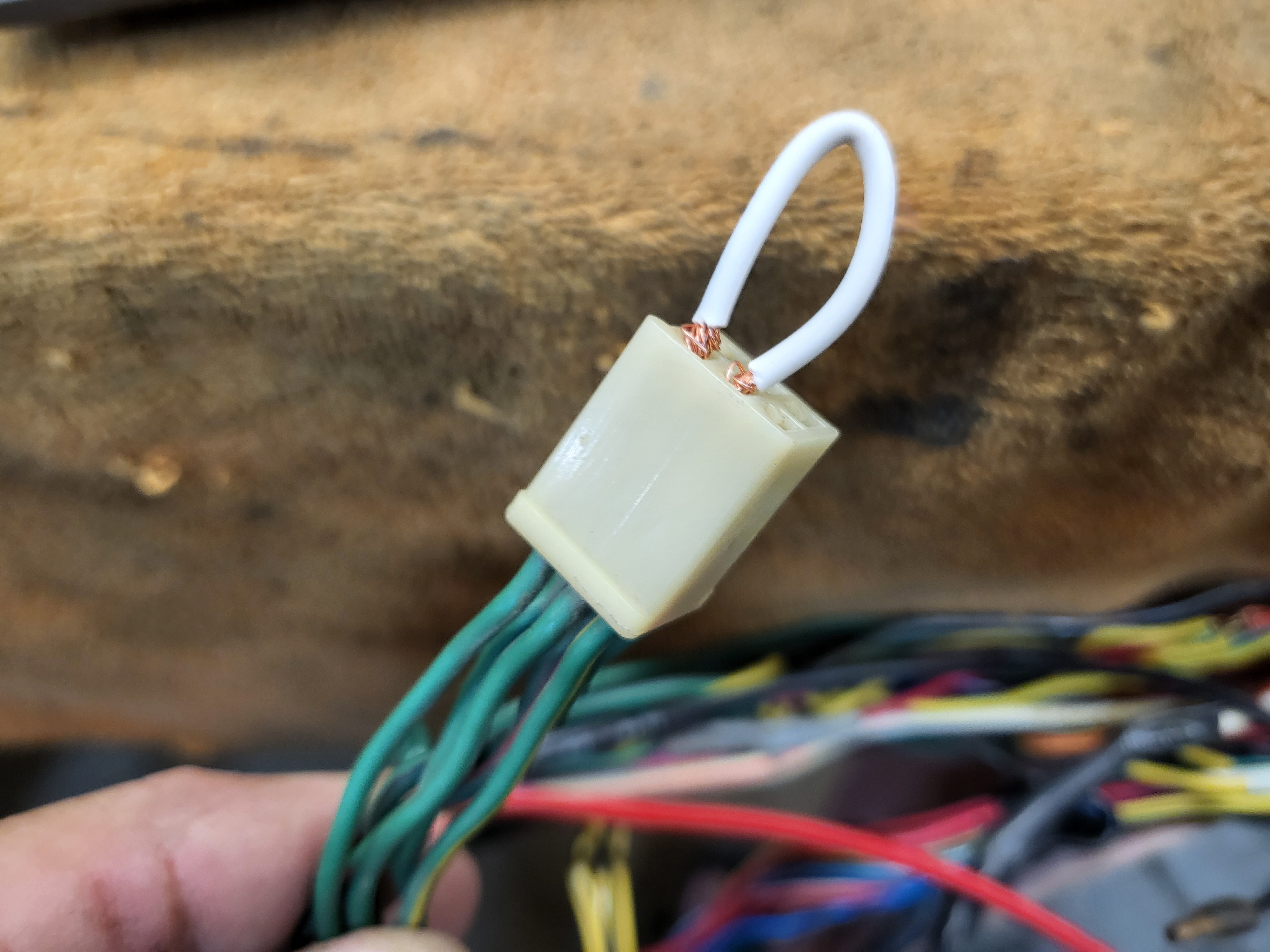
Well, the steel "U" around the wire doesn't appear to be damaged. (while I was still employed as a Journeyman Plumber I used an Amprobe. It had jaws that clamped around a wire so you could measure the amperage that a particular electric appurtenance was drawing. Very helpful with electric motors to see if they were operating within specs. The steel "U" that's bolted onto the back is like the jaws of the Amprobe. It actually contacts with another piece inside and "completes the circle" that makes it's function just like the Amprobe. It's "reading" the amp draw of the coil. I've seen some that have been damaged on the back which renders them incapable of sensing the current draw.) I guess you have a bad tach. Probably some other electronic component inside that lost it's smoke.
-
Yup, that will work. I have one in my 260Z. The high pressure (liquid line) tubing is standard 3/8" OD refrigeration tubing (soft copper) and can be bent with a standard 3/8" tubing bender and flared with a standard flaring tool (NOT an "AN" flaring tool) you can get from any hardware store or plumbing supply or HVAC supply. Nuts and fittings are all standard refrigeration flare fittings.
-
Dcreech, I'd like to see a pic of the rear of the tach with special emphasis on the loop...
-
Sorry, my wording wasn't precise. It will both start and run with the B/W's swapped. If they are in the "incorrect positions" you will loose the tach but since the coil"+" is then wired directly to battery voltage from the IGN ON the "START jumper" isn't needed. You just lose the loop to the tach and power to the coil is not going through the ballast so it will always have full battery voltage.
-
And, yes, there is a "jumper" in the ign switch/coil circuit to bypass the ballast resistor IN THE START position. So at START the coil is getting full battery voltage and in the ON (run) IGN switch position power to the coil goes through the ballast resistor.