cgsheen1
Free Member
-
Joined
-
Last visited
Everything posted by cgsheen1
-
 The bolt threads into a nut that's welded to the frame. It's nearly impossible to keep the threads of the bolt and nut completely isolated (insulated from each other). So, just tightening the attachment bolt through the circle connector will give a very good connection to the frame - no need to scrape any paint off.
 -
That is the main Ground (Earth) connection for the entire electrical harness - actually harnesses. There should be a Ground wire from the battery to the firewall that connects the battery Ground to the frame (unibody).
-
I would also highly recommend you start using only Meguiar's Hyper Dressing on your vinyl, rubber and plastic parts.
-
Uh no, you're not. You're running an internally oiled cam. The spray bar is there but right now it's just acting as a block-off for the two oil ports that feed it.
-
Ordinarily if you're adding a ground strap it would be from the block to the firewall - normally from the starter or transmission bolt to a bolt location nearby on the firewall. I've never found that necessary on a Z car but it certainly can't hurt especially if you're unsure if the stock wiring is "still stock". The intake manifold is generally where you ground all your EFI equipment. EFI grounding can be very specific, and you need to avoid ground loops. Most standalones require all signal grounds to a single point (usually on the ECU itself OR prescribed in the documentation to a specific location) and the other ECU grounds all tied to one spot - either directly to the BAT or block (intake manifold IS same as block (and normally the main battery ground goes directly to the block at the starter...)). The engine is a very "noisy" environment - electrically speaking. Some equipment needs to be wired using shielded cable and the shield needs to be grounded only on one if it's ends to eliminate as much noise as possible for the sensors to report properly. This all should have been in the Haltech wiring information. We installed ITB's on the Swiss 240Z and Tony at UMS here in Phoenix installed and tuned an AEM infinity ECU. It made decent power for a mostly stock engine (mild cam) - 180 RWHP.
-
Wrap the non-adhesive over itself at the start, use a bit of sticky tape at the end and if needed at "tee" offshoots... You'll notice that there are locations on the stock harness where sticky tape is used as markers or to tie off unused (but still present) wires (like the fog lamp wiring up front or the electric fuel pump wiring under the dash and back by the fuel tank)
-
@CO Uh, you mean the 280Z's copied the same plastic taillight surrounds AS THE 260Z... All that great 280Z "innovation" started with the 260Z. 🤪
-
The tabs on the mounting bracket can be bent and may give you the clearance you need. The center bumper section should have a slight curve to it but I've seen them come back from the chrome plater straighter than they should be. (and some people like to get those bumpers really tucked in tight...) I align all the parts and panels to get the best visual out of parts and panels that were never perfect to begin with and after all these years are even less so. From your pics I think the bumper is too high on the left corner and needs to come off the body in the back generally, but that's just me. Leave the bracket bolted to the car, bend the "arms" of the brackets in a bit and then square off the tabs to be parallel to the bumper tabs (you may have some "adjustment" on the bumper mounts too). It may take an adjustment or two or three.
-
Ya, I know that area - raised in Idaho Falls, Grandad lived in SLC. I've driven past Layton 200 times... Do they still use Hill AFB? Still, if he has a heat-soak / vapor lock issue, it may or may not have anything to do with his radiator or fan. Hence my question. (Personally, I haven't seen an e-fan setup that moved as much air as the clutch fan in proper working condition. (haven't ever experienced the Taurus fan setup though). I switched to a Koyo 240Z radiator in my Early 260Z and it cools better than anything else I've used - daily driver, stock A/C blasting (cuz raised in Idaho) on a 115 degree day, L28ET with 12PSI and an intercooler, stock 280ZX clutch fan on the ET... Wrapping my exhaust manifold and down pipe made a big difference in the under hood and floor/trans tunnel temperature. But, like you said we have little-to-no humidity on the west side of the Rockies. Maybe couldn't do that with the humidity in Central America, but that's where ceramic comes in. The difference between here and the Wasatch Front is 20+ degrees and it doesn't cool off here when the sun goes down summertime.)
-
A. What's the temperature in Panama? (closer to Phoenix, Arizona temperature or Northern Utah temperature?) B. What's your WATER TEMPERATURE when you're sitting in traffic? (Is your problem with engine cooling OR heat soak in the carbs?)
-
Uh, BS indeed. I have a completely stock A/C system in my 260Z and I converted it to R134a before I put it back on the road 12 years ago. Stock compressor using Ester oil - Phoenix Arizona... Not that I've never recharged it - I have a couple of times when I pulled the engine - but it's not a "every two years cuz I lost refrigerant" type thing. (I'm also a journeyman plumber (former life) and understand flare tubing very well - so I don't have leaks in joints...) My Hitachi compressor has held up so far, but I have a Sanden on the shelf for when it doesn't. With the mods I've made to the duct system and my Kia blower. I'll put my A/C system up against any other S30, any day (especially in Phoenix).
-
On the lates (260Z ->) there's a metal strip involved that screws to the front of the quarter window frame.
-
There are two adjustment pots on the back of the gauge for syncing the needle with the sender. Ya, that's why no one does it...
-
I have three - used - so I guess you can count me as hoarder... (no blacks, one white, no reds, but three yellows...)
-
He was an awesome guy. In my former life I got to do some plumbing repair work at his house. He had to take me to the garage and show me the SHO he just got from Ford and tell me all about it. We Datsun nuts here in Arizona got to see his Z car up at the Williams, AZ Datsun show a few years back. I'm sure he'll get a good pit assignment up there...
-
Nope, just stuck in the replacements (I felt I'd gone through all other options), fired it up, and watched the AFR's. AFR came back inline immediately so I heaved a huge sigh of relief. We had already checked every other part of the EFI. With the injectors all looking new(ish) and the nasty end of the plugs all looking the same, I didn't suspect injectors.
-
Our experience with POR-15 is that it adheres ridiculously well with metal surfaces when it's applied as they instruct. It was developed to adhere and encapsulate rusty surfaces in a marine environment. They have several products for conversion and encapsulation you might want to look at. We've used it on Z car floors, under cowls and fenders, in wheel wells, and in the area that you're trying to protect as well. But, keep in mind that we're in Arizona so, not a lot of wet here... POR-15 is UV light sensitive but in the areas I've talked about it doesn't require a protective top-coat.
-
Ya, we pulled the injectors and fuel rail and used the ECU. I suspected a few clogged injectors (I knew that they were all opening or at least "clicking") but when they all fired properly and filled the graduated cylinders equally, it obviously wasn't that. The injectors on his engine look relatively new - green top hose type - but they need to be flow tested on a real bench and perhaps resized. The ultra lean condition immediately disappeared when I installed some "known value" injectors. Young Kurtz has done an great job with help and advice from you guys! His undercarriage looks amazing and he has accomplished a great deal. We're going to finish up a little engine work for him and he'll have a nice 280Z to cruise around in.
-
View Advert 1975 280Z "museum car" for sale Bob still wants to sell this 1975 280Z. This is the car we had up on BAT in 2019. There have been a few modifications since then. The bidding on BAT went up to $27,000 which didn't meet the reserve. This car has 4,800 original miles. It is almost all original and in excellent condition. Since then we installed a Nissan stereo radio - this wouldn't have been offered in 1975 and is out of a later model 280Z. We also removed the bumpers, pistons and bumper trim and installed "Euro or JDM style" thin bumpers - stainless steel with no holes. Bob had us install an aluminum radiator when he first brought the car to Arizona which caused a bit of a stir on BAT. We removed the aluminum radiator and installed a stock brass radiator. The story behind the car is this: It was originally purchased in Pennsylvania and traded in with relatively low miles to Thompson Toyota in Doylestown, PA. Thompson Toyota kept it in their collection until 2013. They sold it to the current owner with a dealer verified 4,000 miles on the odometer. I have the paperwork. It now has a clean Arizona Title ready for transfer. The original wheels, tires, and hub caps will come with the car. It has the original spare tire in the well. It is currently on new tires and alloy wheels. All the stock bumper parts are in excellent condition and will come with the car. Even though I've only put up 4 pictures from the BAT auction time period, I have hundreds and can take current pictures for anyone interested. And I'll answer any questions as quickly as possible. Personally I don't think of this as an excellent, original, low milage 280Z - I look at it as an excellent starting point. The buyer will never need to look for interior pieces or replacements for worn out weatherstrip, or trim items, The car has rarely been on the road so the sheet metal, undercarriage, frame rails, and entire unibody are in excellent condition. As are all the lights, lenses, and exterior trim. Gauges, switches, wiring and connectors are all nearly perfect. A great platform for whatever future modifications you want to make. I'm not posting a price - I'm open to serious offers - but keep in mind the final offer on BAT... Advertiser cgsheen1 Date 11/10/2021 Price Category Cars for Sale Year 1975 Model 280Z Vehicle Identification Number (VIN) HLS30-211146
-
That's been so long ago that I don't even remember. I was going to do that but I don't have a fuse cover and didn't remember which fuse. Good call, because I wouldn't have remembered that either. Disconnecting the connector to the wiper motor removed the short so maybe I'll start by plugging in another wiper motor and see what happens. However, I'm more inclined to believe it's in the intermittent wiper timer electronics...
-
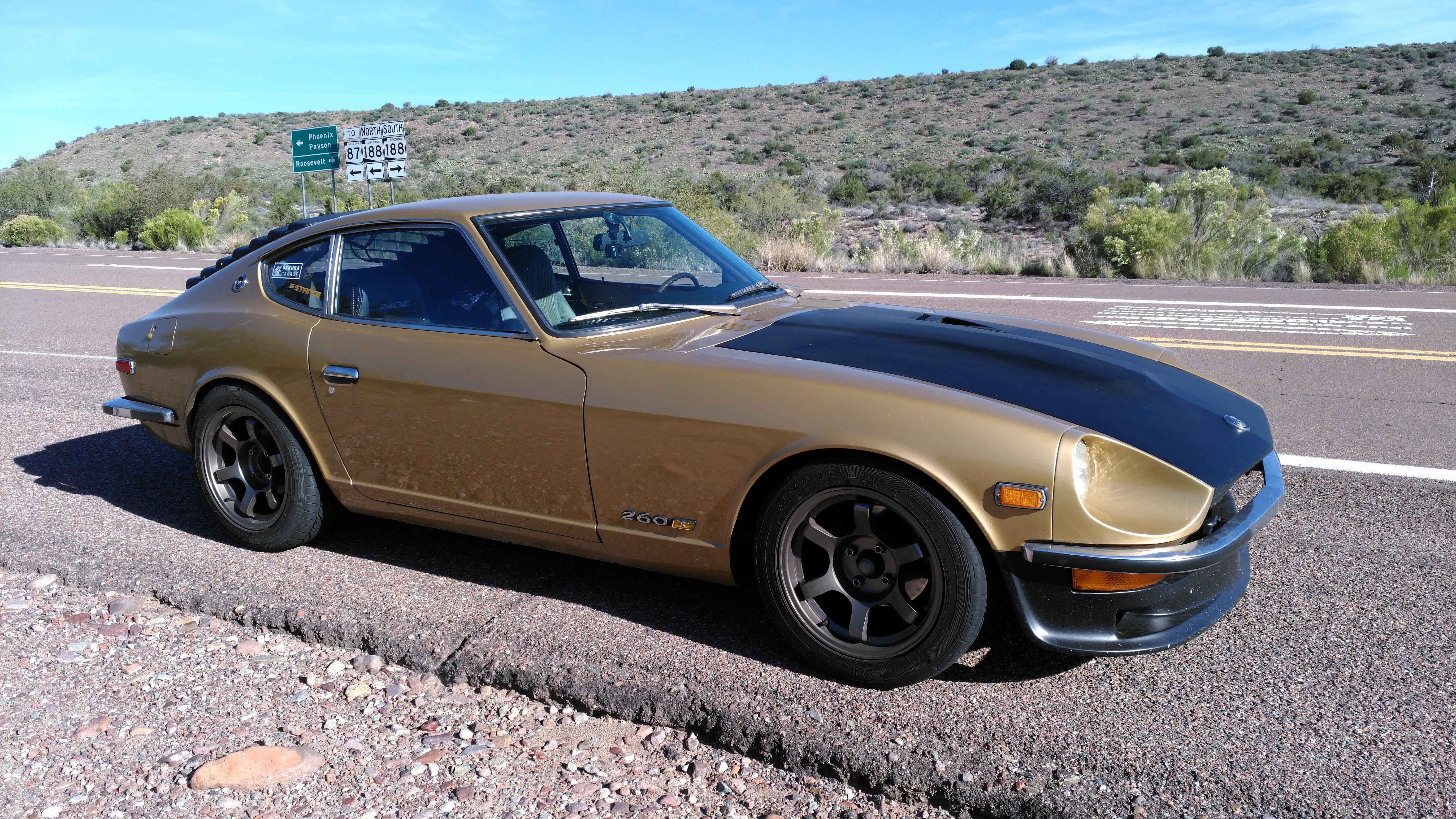
This morning I jumped into Goldie to head to the shop and when I turned the key, the windshield wipers twitched. This has never happened - switch was off, but they jumped just a bit and stopped. I thought it was weird but continued to back out of the garage. I noticed my volt meter (ya, Goldie should have an ammeter being a 260Z, but this was a turbo swap from the beginning of my ownership - with a ZX alternator - so I eliminated the shunt right off and replaced the ammeter with a 280Z volt meter / fuel gauge) Anyway,, I noticed my voltmeter was dropping to 8-9 volts momentarily and it was doing it in a rhythmic pattern. Drop for half a second and go back to normal for 3 or 4 seconds and repeat. Tried the wipers, no worky. Tried to think of what worked in a rhythmic pattern like that and couldn't come up with anything but the intermittent wiper delay. Yup, stopped at the Quickie Mart and unplugged the wiper motor under the hood. Weird voltage glitch went away. Don't know YET what actually caused it, but will be checking through the wiper circuit(s) when I get a chance. Goldies wipers hardly ever get used cuz: A. Arizona... 2. Even though she's my daily driver, I don't ever drive in the wet unless I absolutely have too...
-
Personally I would clean that area as thoroughly as possible and make sure the weep area was clear. Then I would pour rust modifier in-between the panels, letting it soak all surfaces and seep into the pinched seam and drain out the weep hole. Once that was complete, I would do the same thing with POR-15 making sure it coated all surfaces and sealed the pinch seams - again draining out the weep hole but making sure it stays open. Weep holes and drains are an incredibly important part of managing moisture and I would never eliminate or purposefully block them. (My son thinks you should separate the two pieces at the rear of the fender, then do the above, then put them back together using seam sealer. Probably involves a little cutting and welding... Important part of that is sealing both surfaces in there and keeping the weep hole open. POR-15 is stupidly effective.)
-
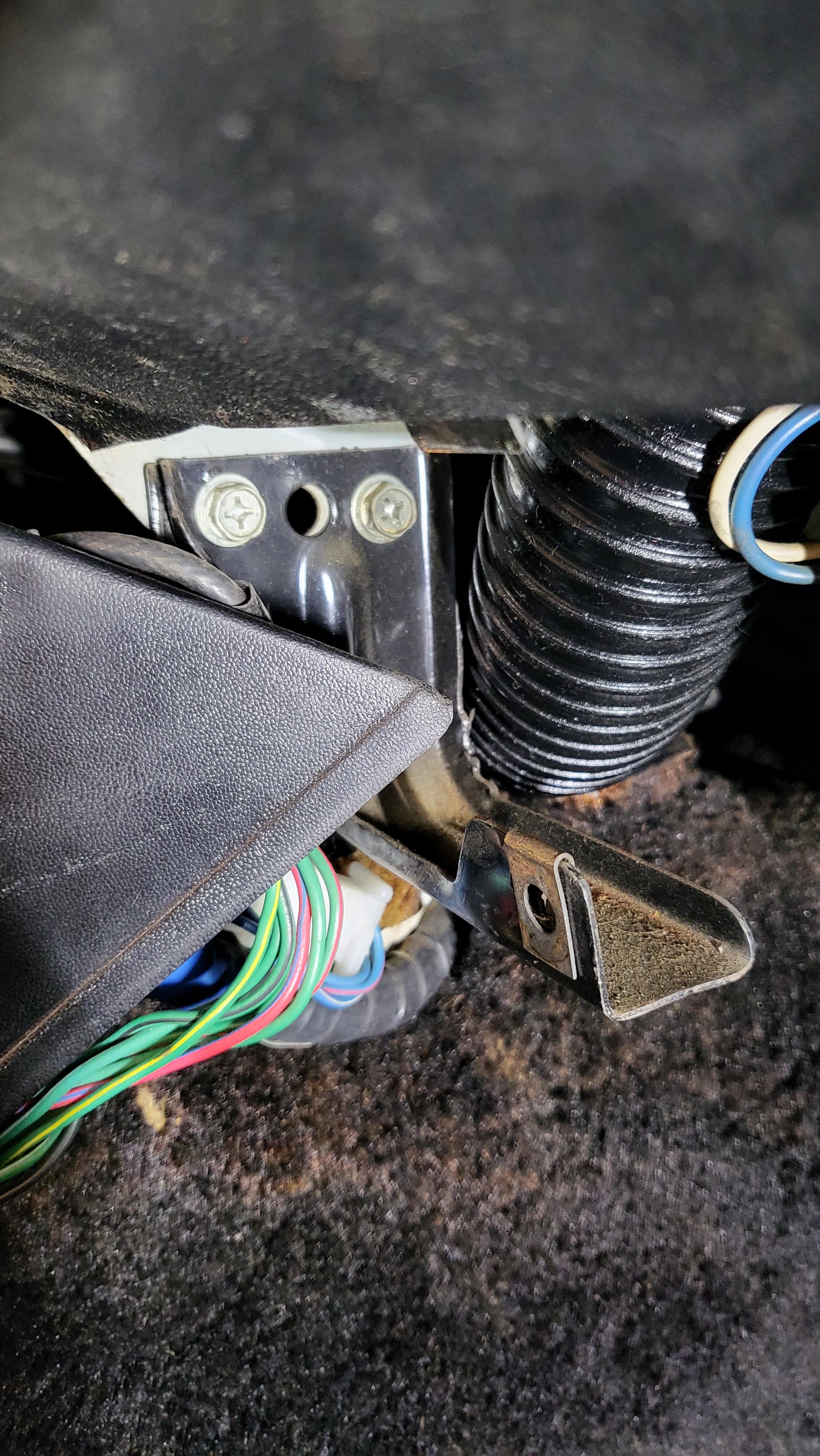
Looking at that in Clayton's car, I thought those were separate pieces. His drivers side has the tunnel-to-dash-frame piece but no finisher bracket.
-
This 280 in the shop only had the right side bracket...

-
There is no "play" there when the engine is turning. The play you have there is only because the cam isn't in a spot where it's resisting the crankshaft motion. Roll the crank a bit clockwise and it'll tighten right up. Then check for chain stretch as per the FSM and linked above. But, if you're that far into the engine already, replace the entire timing set. When the engine is running the tensioner isn't just using the little spring inside it - it's using oil pressure to keep tension on the chain. You can't really mimic that with the engine apart and there's really no need to.