
cgsheen1
-
Posts
625 -
Joined
-
Last visited
-
Days Won
6
Content Type
Profiles
Knowledge Base
Zcar Wiki
Forums
Gallery
Events
Downloads
Store
Blogs
Collections
Classifieds
Everything posted by cgsheen1
-
I installed one in a series one a couple of years ago for a local guy. I have no idea about the sound quality but install was very straightforward, faceplate fit well, and it looks very nice. I don't recall having to do anything out of the ordinary and the fit adjustment was very easy. I moved his antenna switch (as he had a stock type electric antenna) to the console so it didn't impact the faceplate and also didn't modify any stock features (meaning it could be removed at any time and reverted back to factory config and leave no trace of the modification...)
-
What granny said and pull the drums and look for scoring, scratch, rubbing - not so much on the area where the shoe (friction) meets, everywhere else. Put up a pic of your shoes and springs and cylinder.
-
Okay, you did the bushings, springs, and struts plus some powder coat - but what did you do to the rear braking system? Shoes, springs, retainers, cylinders? You left the rear axles and bearings intact?
-
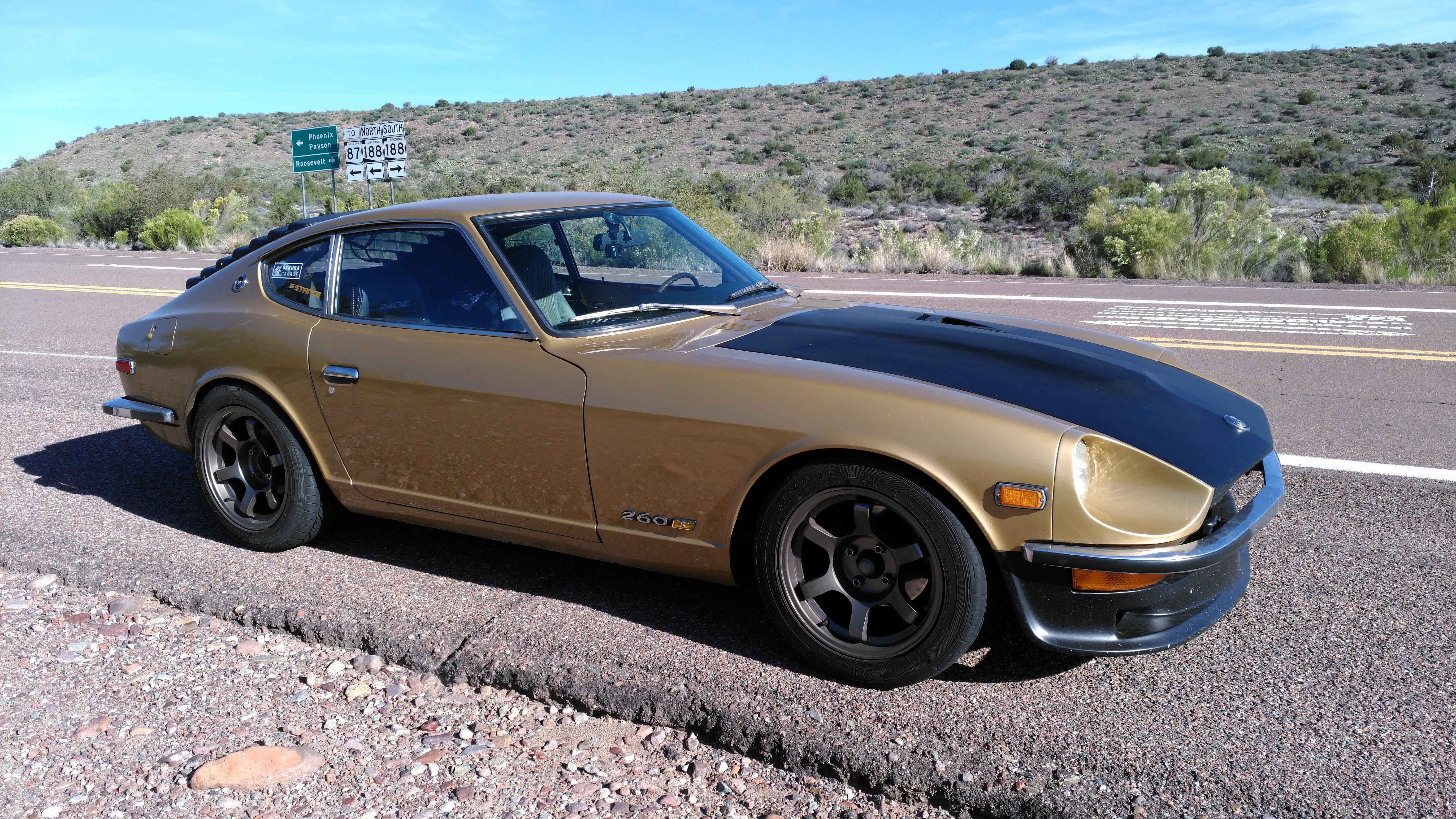
Rota Grid 16x8 +10. I run 225/50 ZR16 (my fenders are rolled (as in: the inner flange with no pull, and as much as you can roll the rear inner flange as it gets pretty "thick" near the exterior...) I have coilovers and camber plates but I run the rears nearly flat)
-
Randy, you can get side bulb welt just about anywhere including amazon. The Kia weatherstrip is nice and you can hide the seam you have to make under the kickplate, but the 90 elbow isn't sharp. With new side bulb welt you can 45 degree each end at the upper aft corner and get the bulb in the dimension you want to completely fill all the gaps between the door and body. (personally, I discovered the Sportage weatherstrip when I was looking for a Honda blower motor for my Z. That's when I found the Kia blower and used it to retrofit my defunct stock blower rather than using the Civic blower. I can't remember the exact year - been too long - but I'm pretty sure it was an early 90's model of Sportage)
-

Sat for two days, now won't start/run.
cgsheen1 replied to NocturnalEmber's topic in Engine & Drivetrain
When you pulled the connector off the ECU did you check the contacts on both the plug and the ECU? We've seen water damage (corrosion, oxidation) on the ECU connector from cracked and/or leaking windshield gaskets. -
Or remove the relays, get back to stock, troubleshoot the circuit and get the headlights working, then get the relays back in... May have helped to know about modifications from the start.
-
The headlight circuit is fairly straightforward. Disconnect both headlights from the harness just in front of the radiator core support (easier than pulling the plug from the back of the headlight bulbs). With the headlight switch in the ON position: Right side: You should read battery voltage on the RED (R)wire. Left side: Battery voltage on the RED/YELLOW (RW). Continuity check: You should have GROUND continuity on either the RED/WHITE (RW) OR RED/BLACK (RB) depending on the position of the dimmer switch. This will be the same on both headlights. The ground continuity should switch wires when you pull the dimmer switch. At least one of these things will probably NOT be true because your bulbs don't light - but you need to know which. https://www.nicoclub.com/datsun-service-manuals has the 1971 240Z Supplement which has the electrical diagrams at the end. From the electrical diagram you'll see that the dimmer switch operates on the GROUND SIDE. The switch gets it's ground from the Lights/Wiper Combo Switch. Power comes from the battery through the Combo Switch -> fuse box (one fuse for each headlight) -> bulb (with several connectors in between all that).
-
That's a shame. A Z that deserved (deserves) to be restored - but who has the $$$$$$ to see it put back near to original... It would take the work those guys in Japan did in restoring the 1969 Fairlady Z.
-
Yup. On the ZX they had to move the blades forward a bit due to the added power steering belt and pulley (three possible belts instead of two). You need the stock 280Z fan and honestly I don't know if there's a difference between the 75-76 and the 77-78. carpartsmanual.com lists the same part number for all the 75-78 L28E and the 260Z L26. There's also no reason you can't use a 240Z fan...
-
If the fan happens to be from a 280ZX, it has a different config than the fans on the earlier 280Z L28E's. The blades are set farther forward on the metal mount. Otherwise I have had difficulty with the new 280Z fans on my L28ET and my Koyo radiator. The newly purchased fan blades were longer (and softer) than the old one I was using and with the engine tilt it put the blades a bit closer to my radiator. What surprised me more was the flex of the blades pulling them into the radiator and actually damaging it at higher RPM. So, new radiator and back to the old stiff, short(er) fan blades... (and, no, I don't use a ZX fan on my L28ET and my frame is an early 260Z - so same rad core support as the 240's)
-
There is no pressure (other than weight of the fluid) in the transmission. Most people tighten both the fill and drain much tighter than they need to be. They only need to be as tight as not to leak. I used to recommend just using Teflon tape on the threads but now use Loctite 567 Thread Sealant and only tighten to snug or slightly past. (got pretty sick of having to use a 3 foot cheater bar to remove customers fill plugs and an impact on the drain...) (I'm a journeyman plumber and spent 35 years cutting and threading pipe. Just like flare fittings, there's science to threaded pipe fittings - which the fill and drain plugs are - just like there's science to the dissimilar metals involved. Tightening a threaded fitting too much is as bad or worse than not tightening enough. "Pipe dope", Teflon, cutting oil (lubricant) it used to control heat caused by friction. Too much friction (heat) causes micro fractures in the metal of the thread which means leak. So, the Teflon is actually more of a lube than a "seal"... Also the more torque you put on it, the more friction there is, more heat to damage the metal. - There, I've given my unsolicited plumbing advice for the day!)
-
Remove the clutch master push rod like Zed Head said - then you can wiggle the fork a little. I've never had to remove the spring and we've pulled (and re-installed) a BUNCH of master cylinders (every single one a PITA)... We've pulled out pins that were worn nearly in half! That's an item that doesn't usually get much preventative maintenance. However - I DON'T BLAME THEM...
-
It isn't easy even when things are stock and not worn. It is typical for the pin to become worn (read: grooved). The groove may (may... what am I saying... WILL) hamper the pin movement. In that case you need to move (wiggle) the pedal while you're prying the pin to find the "sweet spot" that will get the pin to move. (and that's if the wear hasn't created a ridge on the pin that also hampers it's removal...) For me, I cuss at it for longer than I should - then make my son do it. I too would like to see the guy who would be able to weld anywhere near that pin... and live.
-
Can you bleed clutch without lifting car?
cgsheen1 replied to Shawninvancouver's topic in Open Discussions
Ya. On the ground. Make sure your bleed tube goes UP and as high as practical. Air bubbles like to travel up, not down. I don't need a speed bleeder and I do it solo. Same with brakes (although it IS helpful then to have the car off the ground...). I use something akin to this: https://www.amazon.com/FIRSTINFO-Service-Bleeder-Receiver-Non-Return/dp/B010PXUN58/ref=sims_dp_d_dex_ai_speed_loc_touchpoints_mtl_t1_d_sccl_2_1/147-1001020-7876828?pd_rd_w=jJ4sc&content-id=amzn1.sym.3daf75cc-f171-40a9-8276-038202e9f8f1&pf_rd_p=3daf75cc-f171-40a9-8276-038202e9f8f1&pf_rd_r=9CH4W7CA6QJPFA5CTPVJ&pd_rd_wg=8JGXW&pd_rd_r=b2ec40e3-63b6-4cce-87dc-10c7bed01ff2&pd_rd_i=B010PXUN58&th=1 -
Has anyone tried these extended headlight buckets for LEDs?
cgsheen1 replied to chaseincats's topic in Open Discussions
Same. Did H4 housings and bulbs several years ago and swapped to LED replacements 3 or 4 years ago. No sweat. -
No, my '74 frame was always manual so I didn't make any alterations to the tunnel. I don't remember if my 260 even had a transmission when I got it. I did the turbo swap first thing. I have a wide ratio 5 speed and don't like the gearing so I'm running a close ratio ZX transmission. The auto trans swap we did in a complete 260/280 frame was the 1975 all original 280Z from PA Museum car. We removed the original stock console, removed all the auto transmission specific hardware and trim, cut the forward part of the trans tunnel along the top sheet metal line, installed a 71B 5 speed with new boots on the trans, trans tunnel, and console. You can't tell from the inside that it's a swap, you can from the engine bay.
-
They are. We did a auto-to-5 speed swap in the '75 280Z and the console didn't change. The auto trans bits came off and manual shift boots went on. We just trimmed the trans tunnel hole forward using the upper piece of sheet metal as a guide. Then just check the shift lever clearance. I have a close ratio ZX 5 speed in my 260 and I definitely bent the rod - BUT I used the straightish ZX shifter, not the early Z shift lever...
-
I don't know if this is "internet wisdom" or not but I've generally heard that the cast iron impeller is more efficient than the stamped impeller. The old timers always seemed to recommend the cast iron. If you have the proper coolant mix there is no reason to select stainless over cast on the corrosion issue.
-
280z Auto to 5 Speed swap-- Clutch pedal height
cgsheen1 replied to sboy79's topic in Engine & Drivetrain
They certainly did and you can tell from his picture above that he has a 260/280 style clutch pedal. The 240Z clutch pedal was thinner metal and had a curve from top to bottom to give it strength. Then you can talk about the changes in the pedal boxes from series one on as the brake booster changed dimensions... -
There's no real reason to leave it up and in the way. It's just four bolts forward of the clamshell to remove and then push it down. Just as easy to raise it and bolt it back up when the dash is back in.
-
Yes, there are metal inserts in the foam with holes and most are accurately placed. Have installed a couple 260/280 and a few 240. Not saying that they are entirely plug and play but well worth the effort and an extremely nice end result.
-
That's not the only attachment. It's held in place on both sides by the tail light surrounds and also by the license plate. If everything else is in place, it's kinda stuck there...
-
Door Internals Window Mechanisms Regulators, Etc
cgsheen1 replied to Captain Obvious's topic in Body & Paint
There's more to window movement than just the regulator so do yourself a favor and break the whole thing down. Take the squegee and trim piece off the door, remove the window frame - you'll probably need to unbolt and possibly remove the forward guide but you'll want that out anyway to clean and lube, remove the glass, remove the regulator, remove the short horizontal guide that's amidships in the door (cuz you probably want to clean and lube it too. Check the felt running down the lower portion of the frame. May not still be there - I nearly always replace than with a strip of window channel. It keeps the window glass from bouncing around and provides a glide path as it goes down. You usually don't have to mess with the lock and latch stuff but now's to opportunity to make sure all that stuff is cleaned and working too so you don't have to crack the door open again in the near future. Then check all the parts for wear or damage and clean and lube as needed. I've found it often takes more time and effort to get one little thing out and back it than to dis-and-reassemble the whole thing. -
Various sections show a simplified schematic for each circuit examined designed to give you a basic idea of how the appurtenance is wired. Not a detailed schematic of the entire circuit or system. Note also that the wiring diagram - even though it's complete - doesn't actually show how each wire is actually laid out in the various harnesses. You usually have to dig a little deeper - which you eventually did... Looking at the wiring diagram, one might say that since your megasquirt is now firing your coil rather than the TIU, that the blue wire should have been disconnected from the (soon to be abandoned) TIU itself and connected instead to the megasquirt output to the coil. I had a question about this: Megasquirt only needs the one connection to the (-) side of a single coil system in a Z since the stock B/W wire provides power at IGN ON to the (+) side of the coil. If you removed the ballast, the B/W simply needs to be transferred from the ballast to the coil (+). The B/W wire(s) in a Z are always battery voltage at IGN ON. That may simplify your wiring - as would just using the L wire removed from the TIU under the dash to connect to the MS coil output. Then you wouldn't need additional wires to the coil (just leave in place the stock L and B/W)... It's been a few years since I used a single coil with MS but I'm pretty sure that's accurate.


