cgsheen1
Free Member
-
Joined
-
Last visited
Everything posted by cgsheen1
-
 Light. Console. I think G/W is clearance, gauge lighting, and etc. but I'll look... 72_dash_2.pdf The 240Z dash I have has that same connector - the entire dash and harness is unconnected so... But - the G/W on that connector traces to the small 6-pin Body Harness connector shown in that .pdf - G/W in the upper right corner of the connector. The body harness G/W goes back to the clearance lighting in the tail. Trace that Red - I think it may well go to the front (engine bay harness) and the two hidden Fog Lamp connectors in the harness as it spans the radiator core support. And as you know the US model did not come with a Fog Lamp Switch from the factory so that would be an unused connector if what I said is true. Oh, if you look at the first wiring diagram in the FSM (not the "US and Canada Only" schematic) you'll see Fog Lamps and the connector for the Fog Lamp Switch. BUT, it'll confuse you because it shows a R and an RG wire to the switch. If you trace the RG, you'll see that it "tees" off a GW. So maybe the schematic doesn't follow the harness build exactly or vise-versa...
 -
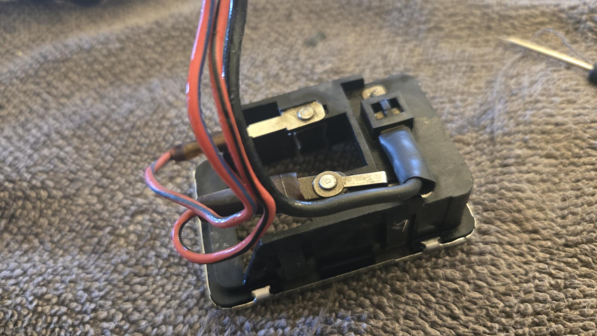
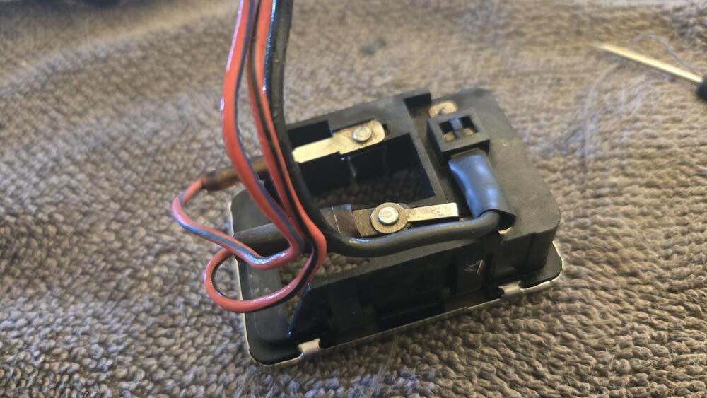
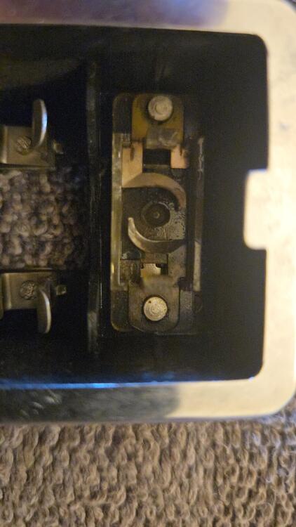
Here is how this one was wired: Main GND (B) is a male spade that pushes into a female held in that little box. Red/Black (RB) is the GND from the door switches. Red/Blue (RL) is +12V from the fuse box. And they're both female spades. You'll notice that the main GND can be interrupted by the switch and that the RB GND from the doors is independent of the dome switch. Now. To refurbish this one AND try putting it back together - so that it still works...
-
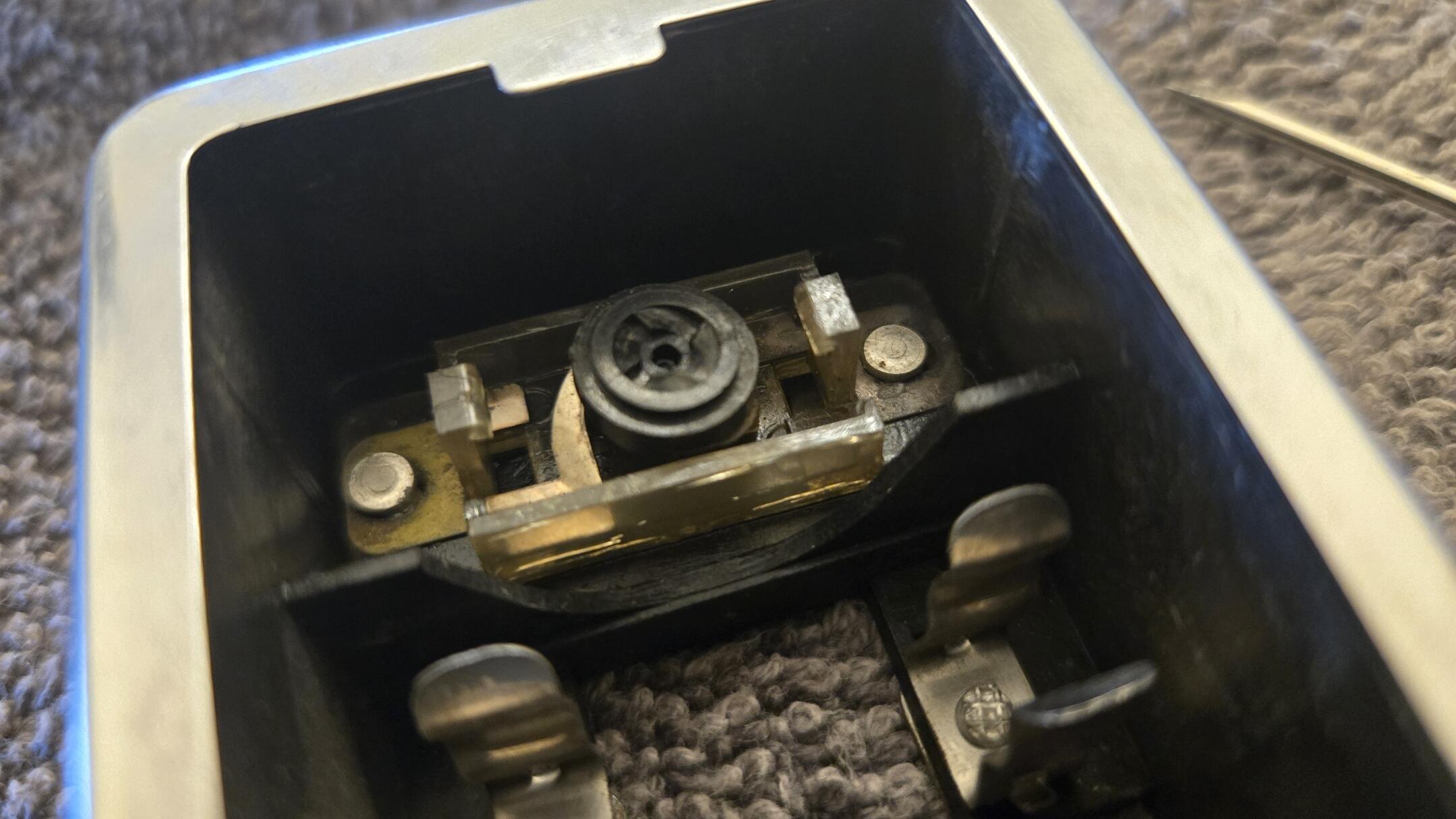
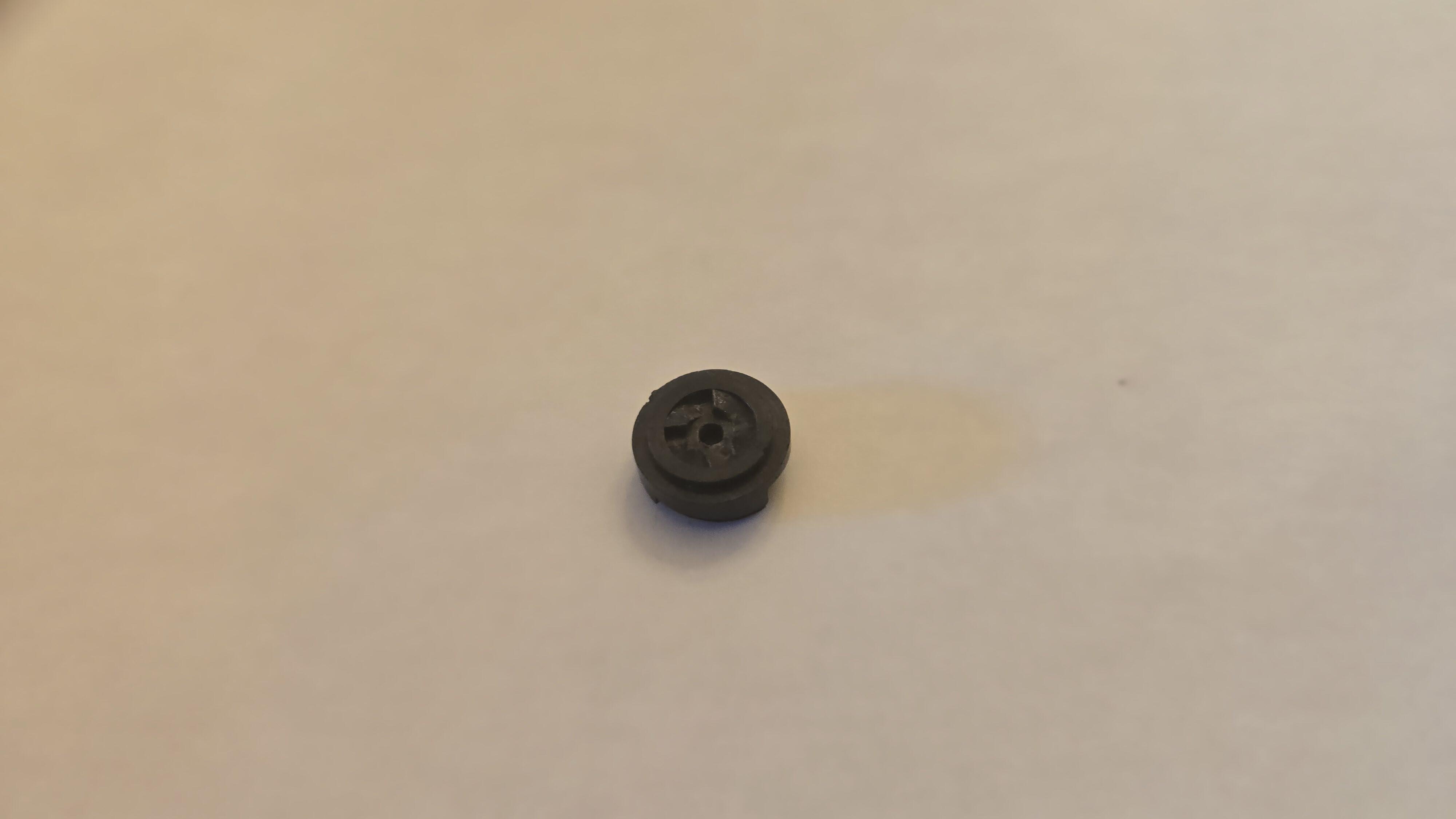
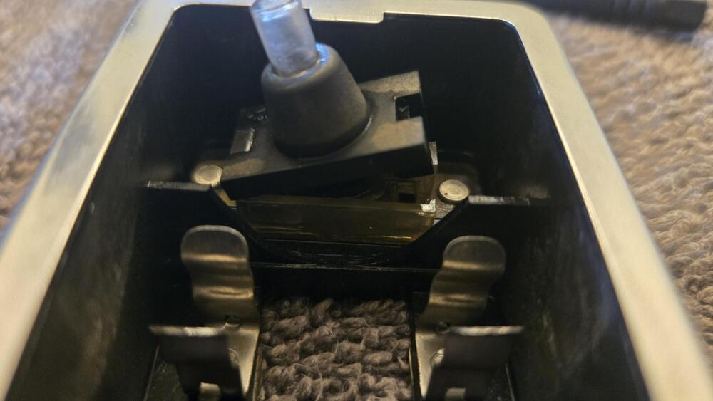
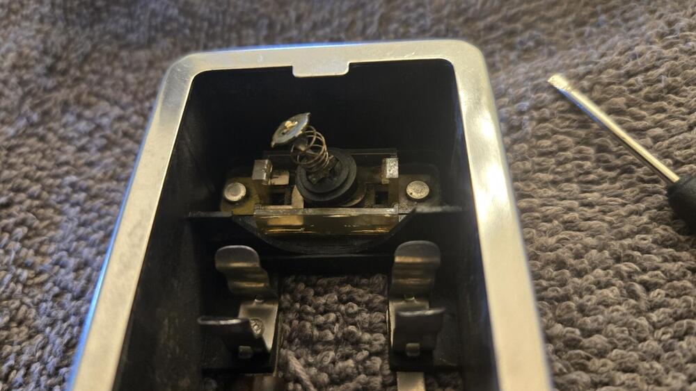
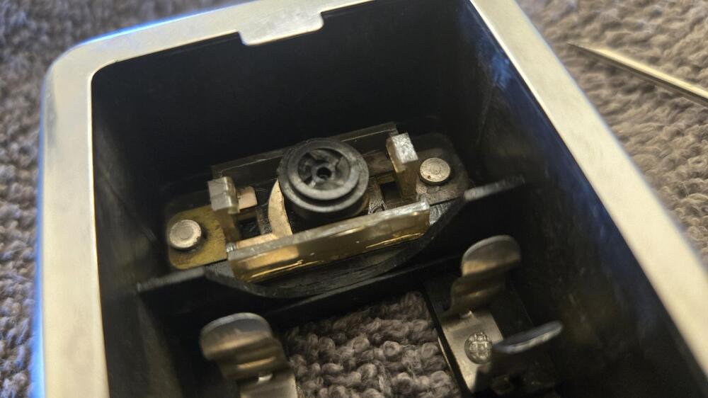
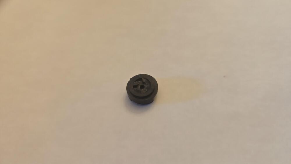
Weird - it's a turn-y switch - it rotates into or out of contact by pressing the button. That little black disc (brass contacts on the bottom side that I didn't take a pic of...) gets turned by the shaft above it. So, it needs to turn freely, have an undamaged top side (the little ramp, triangle thingy's), and the entire mechanism needs to slide / move freely, and all the contact brass needs to be clean. I didn't notice any old grease or lubricant in this one. I was surprised that the "top" was just held on by a couple of clips on either side. Everything is PLASTIC and we don't have very good luck with PLASTIC here in the DESERT, so I was a little nervous. I heated the whole thing up a bit and used an extremely small screwdriver to pry one side at a time. First side was pretty easy - the second was quite a bit harder but eventually the "top" came off and revealed the underlying surprise. The switch is indeed simple and you can test continuity straight through on the rivets both sides or the brass the rivets tie down. Also check continuity through to the bulb holders to make sure corrosion hasn't killed the circuit between the switch and the bulb.
-
I don't see anything unusual other than it has two possible grounds - one that can be provided by the dome switch and/or one that can be provided by the door switches. No one of them interferes with the operation of the other(s). All can be providing (or removing) ground in any combination of the three. The dome light switch itself looks fairly simple.
-
Hmmm, that's one switch that I've never taken apart... Now you have me curious. I think I'll see if I have a spare and drill out the rivets.
-
Yes on the White/Red. Through the hole in the back, attach to the screw lug in the middle right.
-
-
If you need headlight buckets, I have a few.
-
I'm no expert but in the inertia switches I've installed I've mounted them to a hard point so any energy exerted on the unibody could be picked up by the switch.
-
Both are under the center dash. In the blower switch harness is a BLUE that is A/C power. And there is also a 2-pin connector with a B/W and a G for power to the fuel pump. I always put an inertia switch in that circuit.
-
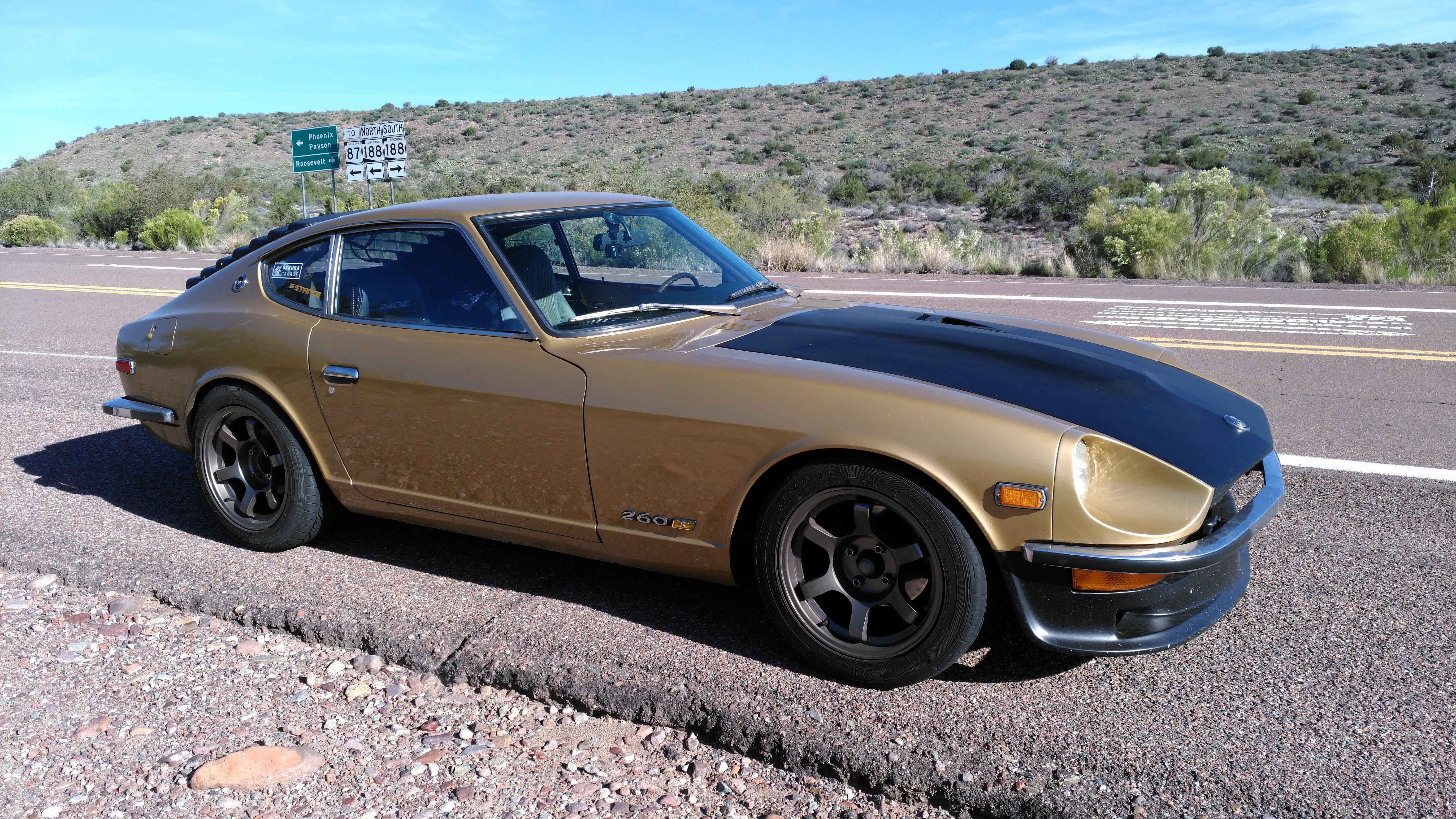
Like the Z's here in ARIZONA...
-
Outstanding.
-
Yup, and those pillars are a bit more complex than they look from the outside. I've cut apart a few Z's and the lower center section isn't as strong as one would hope - I'm sure you're careful in it's support with the roof skeleton removed. I'll be interested in how you reconnect the center sheet metal in the pillars. There are an awful lot of people who painted over that Yellow...
-
Maybe this is the point where you decide which you want most - working tach or good running engine... Back when I learned to drive - and for years thereafter - cars didn't come with tachometers. They ran and we drove them all over the place anyway. (but, from the factory that car ran VERY WELL with a stock coil, a stock ballast resistor, a stock distributor, AND a stock tachometer. Just sayin')
-
Okay, cool. thanks for the correction.
-
Easy test, take the ballast RESISTOR out of the equation: Take the G/W wire OFF the ballast, hook it up to the B/W that's connected to the other end of the ballast. Run the engine. Is it better? Is it worse? Don't notice a change at all? (Better: leave the ballast out - figure a good way to connect the G/W and B/W permanently cuz VOLTAGE. Worse: hook it back up the way it was. No diff: Hook it back up the way it was - if you're sure there was no change.) (I haven't said yet what I'd really recommend which is: replace all your harness wiring, especially the engine bay harness which suffers the most degradation over 50+ years of living on this Earth... Few people listen - even me - I'm just barely doing that in my own car (and it turned 50 last year).)
-
O.P., you should probably pull a spark plug or six and see if (how much) they are sooted up. The Fuel Pressure Regulator (FPR) on an EFI engine is "vacuum referenced" or Manifold Absolute Pressure (MAP) referenced. Meaning it has a hose connection to the intake manifold. The FPR is supposed to maintain a fairly constant fuel pressure differential with the manifold pressure. Nissan uses 2.5 BAR or 36.3 PSI as the required differential. That means WITH the engine NOT RUNNING and fuel pump RUNNING the pressure to the fuel rail and injectors should ~36.3 PSI. When the engine IS running, the FPR will SUBTRACT the manifold pressure while under VACUUM or ADD the manifold pressure if under boost (positive manifold pressure). You don't need to consider boost. But, say you have 10 PSI of VACUUM while the engine is running at idle, your pressure at the fuel rail and injectors should be ~26.3 PSI (36.3 - 10 PSI). First: The ECU DOES NOT get the "tach signal" - that circuit if for the GAUGE ONLY. It is pointless to look for it. The Electronic Ignition Module figures out when to send a signal for the coil to fire - it gets the information from the distributor electronics (pretty sure - I haven't handled the original Bosch L-Jetronic for a blue moon...) Second: Have you tried operating the engine WITHOUT the cold start valve? Disconnected from wiring and/or fuel? (IS your engine only running on the cold start fuel??)
-
Stock wire? How green (or brown, I mean oxidized) is the copper? That's a long run between the ignition switch and coil. Oxidation = increased resistance. If you take the ballast out of the circuit is it better?
-
First thing - the AFM does indeed have a wiring connector, it's of Bosch design (as is the entire EFI system in your Z) and it's, like most Bosch connectors of that era, a PITA to remove. If your AFM is in place it will be difficult to see as it's underneath all that. Second thing - you really need to make sure the injectors are opening. It's sort of easy if you have the right stuff, and can be done in place IF you know how to release and remove the BOSCH injector connectors... If for instance you HAD a spare Bosch injector connector with a pigtail, you could put it on each injector in sequence and use a 9-volt battery to quickly apply and remove voltage to the pigtail wires. Yes, a 9-volt battery will open an injector. If you hear the distinct CLICK of the injector opening you can immediately rule out the "crapolla, the injector is stuck closed". (here I have to say: one side of the battery needs to be permanently connected, the other (doesn't actually matter which) needs to be loose so you can just tap the exposed wire end to the bare pole quickly. You DO NOT want to hold voltage to the injector except for a very brief period of time - that's how they work, milliseconds... IF STUCK they in truth need to be pulled and cleaned (and flow balanced) by a professional shop OR replaced - BUT most of the time I can get a stuck injector opening again by rapidly tapping the wire for awhile (several seconds or more) until I hear it clicking. That may help you in your effort to get it running even if things are not all perfect. The injector is a coil (an electromagnet) so both of those spade connectors are actually tied together by the coil. You should see that when testing with an Ohm Meter - leads placed on the two should show a steady Ohm value. If that circuit is OPEN, the injector is bad and you can't fix it. Now, you can also test that the injectors are getting voltage - they should ALWAYS show battery voltage if the Ignition switch is in the ON (or Start) position. And, because it's a coil, you WILL see voltage on BOTH sides IF the harness wiring is connected to the injector. If the injector connector has been removed you will see battery voltage ON ONE SIDE of the connector an not the other. The ECU asserts a ground to the other side of the connector to open the injector and, like I said, this happens FAST. You will never see this activity with a meter (oscilloscope yes). Because they are basically a coil IT DOES NOT MATTER which side gets power and which gets a ground signal. Most people wire the "hot" side consistently to one side of the connectors, BUT they don't have to! There is NO "+" side or "-" side. If there was, the injector would tell you.
-
No. The tach is connected indirectly.
-
Couldn't help you with that, but I doubt either part would keep the tach from operating if it's wired properly (the tach and coil) . And if it's running - and running well - why would you think there might be an issue between the MSD coil and Pertronix module? The distributor module (Pertronix, points, 280ZX "matchbox", whatever) gathers info from the crankshaft and sends a "signal" for the coil to fire. It momentarily asserts a Ground on the coil "-" terminal. The rotor "distributes" the released coil energy to the various spark plugs at the appropriate time. If any of that isn't working properly there would be no well running engine.
-
You can download the Factory Service Manual for every year of Z car at nicoclub.com ( https://www.nicoclub.com/datsun-service-manuals ) Coil specs: Engine Electrical EE-26. Electrical Schematic: Body Electrical BE-5 I described the wiring for the tach operation above but: The coil gets battery voltage at Ignition ON through a Black/White wire. Black/White is a Nissan standard throughout the Z cars of the 70's for "battery voltage (or whatever the alternator delivers) when the ignition switch is in the ON position. NEVER assume a Black/White wire in a Datsun has anything to do with GROUND - IT DOESN'T! BUT - the 240Z Tach works on amp draw. SO, the tach needs the B/W that powers the coil to run through it (the tach) FIRST (before it feeds the coil). A ballast resistor was common for ALL single coil distributor engines of that era. Nissan designed the circuit so that power to the coil when through the BALLAST before the tach and coil. That's why the wiring is a bit confusing. IN THE STOCK CONFIGURATION, There are three (3) wires that make this happen: TWO Black/White (B/W) wires and ONE Green/White (G/W) wire that are in the harness bundle that pass in front of the radiator core support and then through a hole in the left side and end up in the coil area. (The coil and the ballast resistor are side-by-side) IF all three of those wires are temporarily disconnected. ONLY ONE of those two B/W wires will have power at IGN ON. Stock config: The B/W with battery voltage would attach to one side of the BALLAST. The Green/White (G/W) would attach to the OTHER SIDE of the BALLAST. The G/W returns to the TACH. From the Tach, the SECOND Black/White (B/W) RETURNS to the COIL "+" terminal. (IF you were eliminating the ballast for some reason, the B/W with power should attach to the G/W so it feeds the tach before sending power to the coil through the second B/W...) THUS: B/W from IGN Switch -> BALLAST -> G/W back to TACH -> B/W to "+" side of COIL...
-
Dang! Pictures of people in sweats! Down here we're still just sweating... 🤔
-
It sounds like the tach itself. From your description I would imagine there's a part inside that let the smoke out. I doubt the coil itself is going to have that effect. Perhaps removing the ballast had a role, perhaps not. Like Yarb said, maybe it's just old. There are discrete parts in there and perhaps the culprit could be found and replaced. The tach is just reporting entity and has no physical connection to the engine or coil. There is a battery positive and ground for power, but the "signal" is isolated - that wire is not physically attached to any part of the gauge. If you look at the back you'll see the G/W feeds a looped wire that goes through the same sort of device that a "clamp meter" (ammeter, amp probe, or the clamp that goes over the spark plug wire on a new-fangled timing light) has.
-
I can see from your pic the fun that the body man is gonna have with the lower fender and rocker and/or dogleg... Completely typical though.