hr369
Free Member
-
Joined
-
Last visited
Everything posted by hr369
-
 You could probably fix it yourself with a heavy duty thread and a big needle.
 -
If anyone is interested, i've archived over 2600 zcar related pictures on my google drive. link to google drive
-
 but they look like new.
 -
-
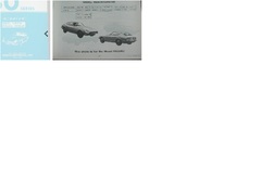 rhd parts catalog. expensive
 -
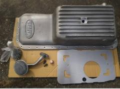
Someone already posted the ebay auction of it there. I see a few people i've sold fairlady parts to. I have another box of goodies i'm going to pick up in nov. Anything in there u need? .
-
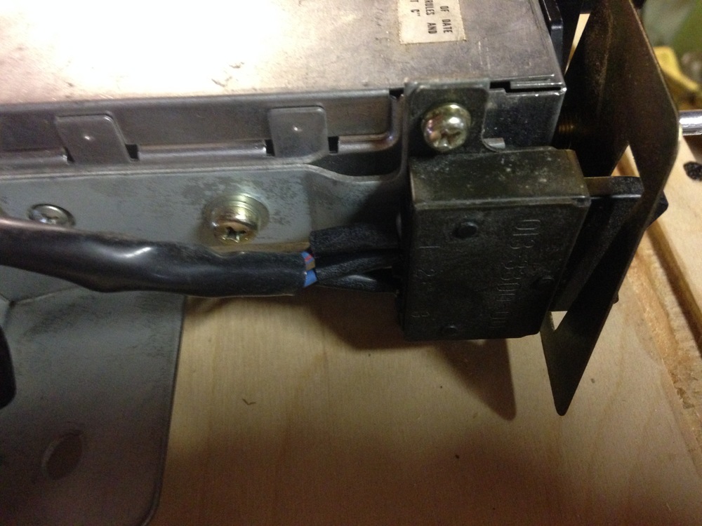
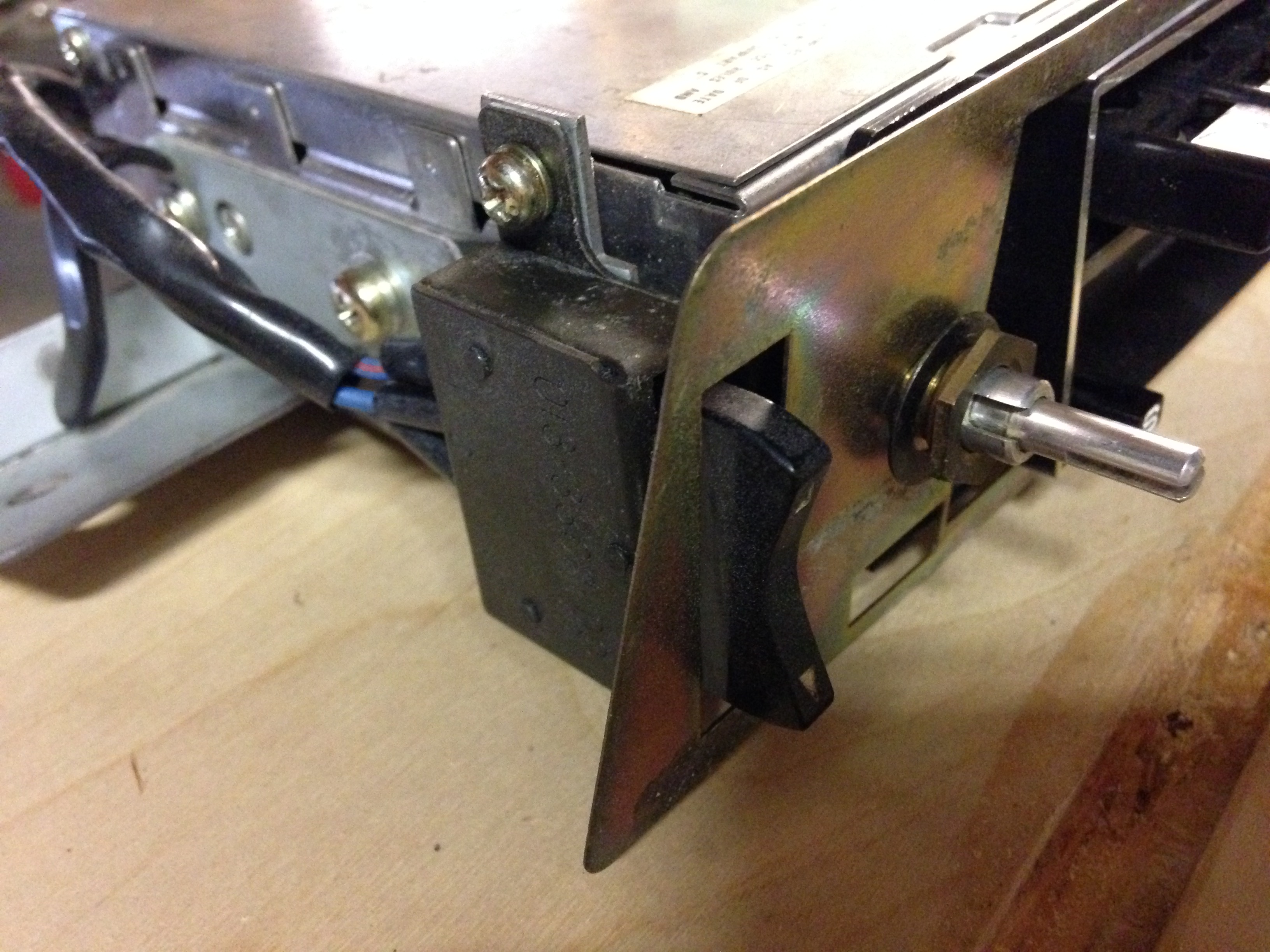
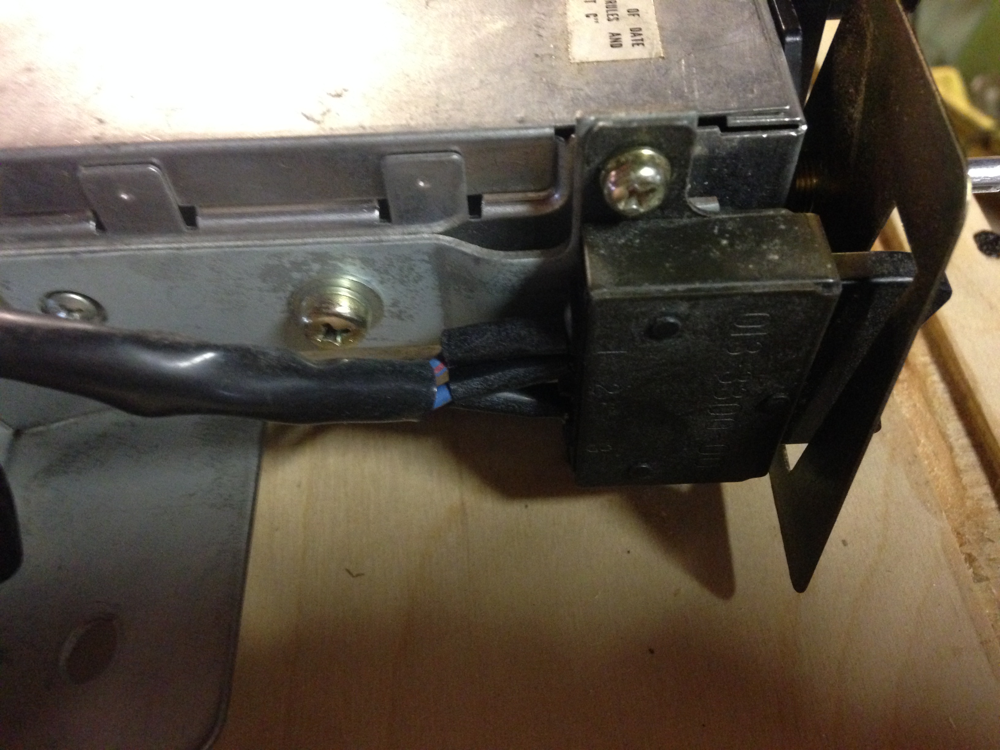
Yep, a 78 280z faceplate should fit on that. Good price you got. Nice upgrade too with the 5 pin din and stereo instead of mono which 75 z's had. All you need now is a faceplate and antenna switch. This is the mount they used. Nothing fancy.

-
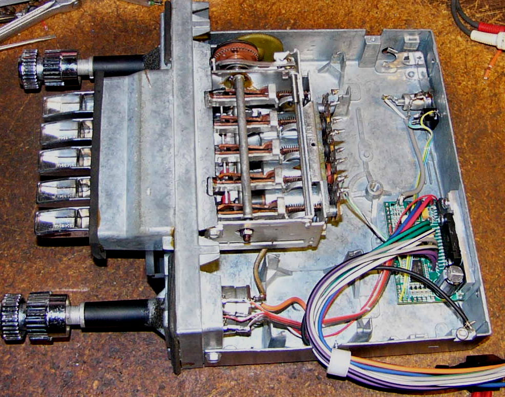
Yes you can put an aux in on your radio. You can hard wire it like the guy in this tutorial did. Disclaimer, i haven't done this yet so don't know if it works yet on our hitachi's You can also use one of the universal line in units that plug into your antenna and send the signal over fm. BUT yo're still stuck with mono with that radio you have. ebay link fm modulator The red with blue is the + for the dial lighting when you turn on your lights at night. The ground is the speaker wire with the stripe on it. What model radio is that? I've never seen one that has the red with blue tracer without a black wire also. link to aux tutorial What's really slick is how some people are gutting all the electronics inside their stock radio and putting in modern electronics. The sound quality is much better. Look at that tiny board in there. youtube video of upgraded radio

-
Your options are very limited. Since you're paying someone to fix it then i'de suggest a used exp valve. You already know about the generic evap core and its cost. used exp valve ebay
-
280z hitachi has the push on. 280z faceplates come up on ebay quite often.
-
double post
-
Good job. Sounds like just a cold solder joint. Sometimes transistors test good but are bad. You ever use freeze spray or heat to test? The lighting is really bad in the video. From what i can tell, that radio looks like the ones they had in the 82-83 sentra's and it looks like a very close match to the kms2411 78z radio's i have. I just robbed my km-1821ze for a RF transistor to go in a 240z radio. Love the interchangeablity of hitachi stuff so don't toss it if stops working completely. You might be able to put a 77-78z faceplate on it and attach a 78 antenna switch on the side with sheetmetal screws. I think i saw a 5 pin din on your radio too. I bought a cable on ebay that allows me to use a 3.5mm jack for an iphone or mp3 player.
.thumb.jpg.2861952eb50a0f438c79f7290b33ecd0.jpg)
.thumb.jpg.d17ff35e39a9a305a0004e13cc4734fe.jpg)
.thumb.jpg.9b5bb131e39198cb1d7331d51b101001.jpg)
-
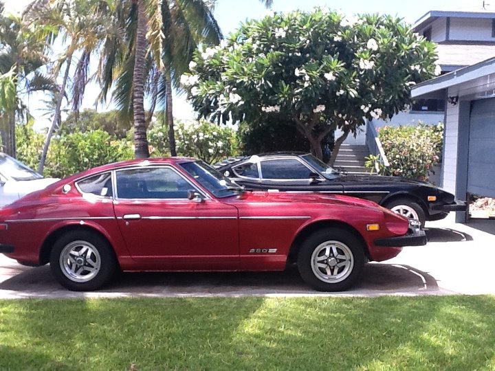
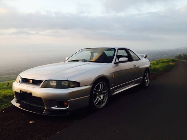
Only 4 more years until its legal to have in the usa. It's a 35,000$ gamble. Apparently It's easier to fly under the radar in hawaii. Any takers? craigslist ad Thinking of selling my Gtr asking 35k it's a real deal v-spec one of 1650 made in all the years of r33 has a twin turbo rb26 and is rhd! Car is basically stock the only upgrades are hks intake system and full exhaust all the way to the turbos. Car also has water meth injection and is running 15lbs boost on factory Garrett turbos. I just replaced all four tires and added a carbon front lip, timing belt was also done and now has Greddy Teflon belt. Car has cold Ac and currently has 60k miles please don't call and ask questions about how I got it here and legal! Iam very busy and not trying to answer a million questions. Only contact me if your serious and have funds in order or a serious offer or deal proposal!!! Car has a Hawaii title and everything is up to date! Text is best (808)463-404zero
-
"stereo datsun radio thats coming" You said at the end of your video. What kind of radio is this new one? Your first radio you bought has FET's ? what kind of radio is this? The OE hitachi i have has NPN's
-
I've heard some people baked too long and/or too hot and it screwed up the finish.
-
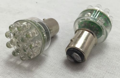
Got LED's in those lights? They saved me from a drained battery one time when i went to work and the brake light switch failed and the brake lights stayed on for my entire 8 hour shift. When i came back to the parking lot i thought my battery was drained. It started right up.
-
Some people have baked their newly plated parts in an oven to harden the coating. You mentioned hydrogen embritlement in the first post on this thread but nobody answered your question. Perhaps this may help? finishing dot com website
-
Good job. I might try clear coating the set on my car.
-
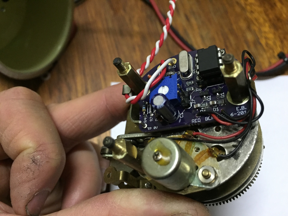
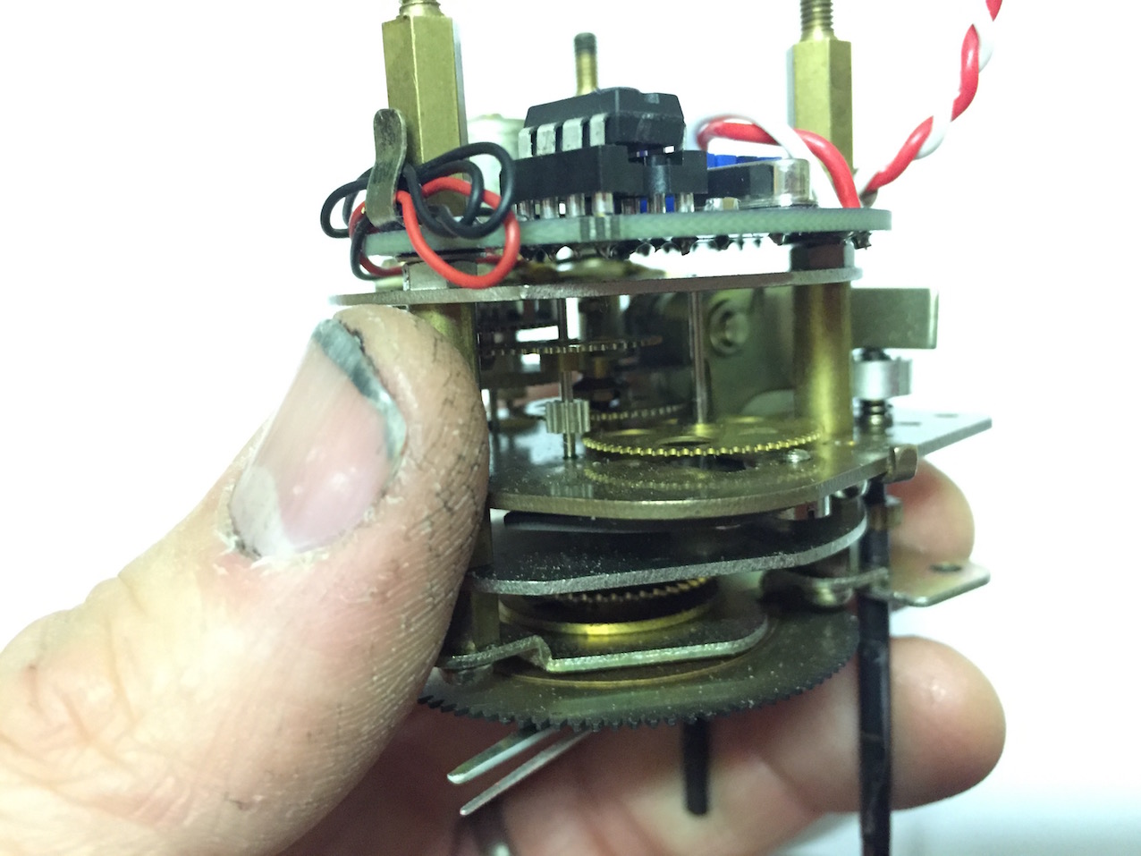
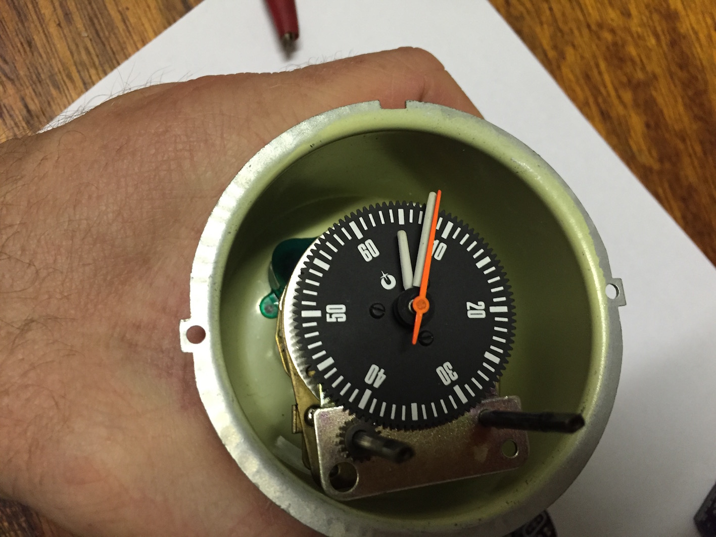
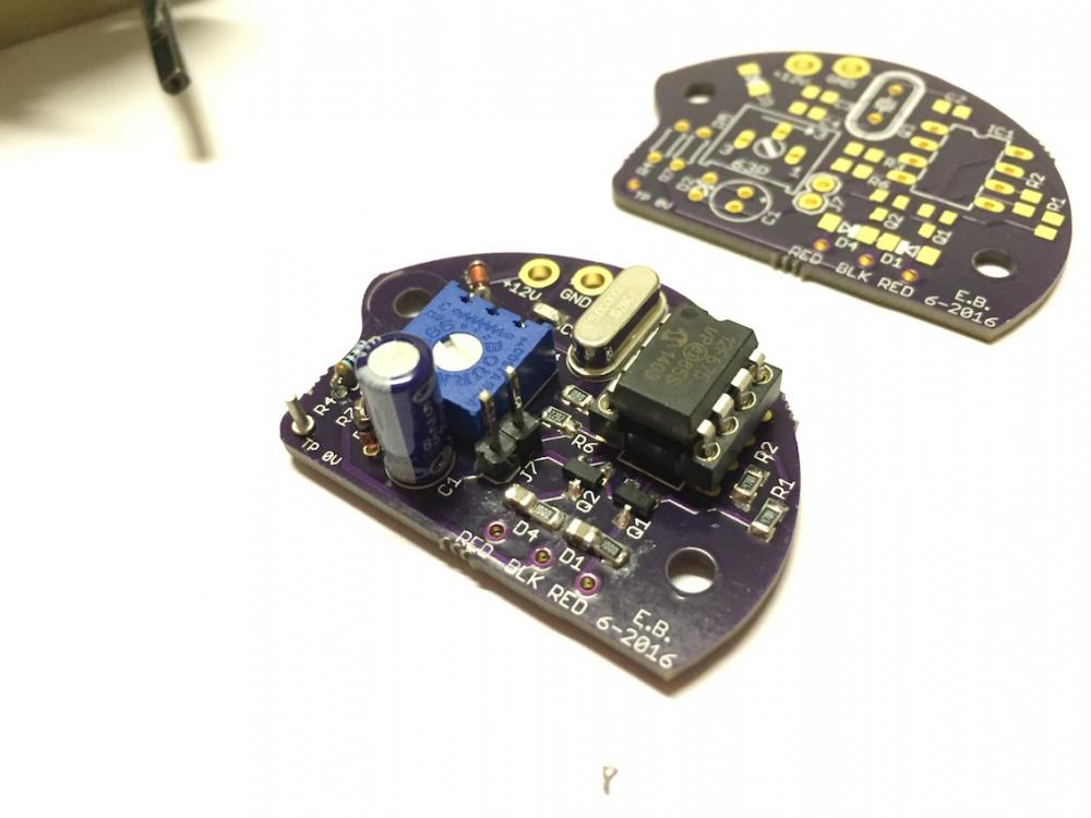
Ok, this is our version 2.0. of the oscillator. Eric is going to send me a copy and I will try it on different clocks to see how accurate it it keeps time. We have a speed adjustment pot just just like the original oscillator had just in case. Fits nicely in the place where the original smaller circuit board was. oscillator running youtube


-
Less than 1/2 the price of the Amelia island auction car. I say bargain if the original wheels go with it. yahoo auctions link
-
red tek 12a is a hydrocarbon refrigerant. Probably propane + isobutane. Have to look at the msds sheet to see what it contains. I ran something similar to this in my 280z called envirosafe. but i must say that it didn't do very well. I then tried r134 and got colder temps. It may be something about my system that makes r134 perform better. I don't know. I tried the recommended pressures and higher than recommended with the same results. I DO run envirosafe in my toyota. Its a 1990 r12 system converted over and it will freeze you out. With a used compressor you drain as much of the mineral oil out as you can and flush it with pag oil. What little mineral oil thats left should mix with the mineral oil. You can try running red tek and see how it works on your system. They say that systems with small leaks don't do well with mixed refrigerants. The refrigerant with the smallest molecules leaks out first and you're left with a poorly performing system. Also, If you're afraid of blowing up in a big ball of fire in a wreck.... a whopping 3-4 lbs of propane gas then do NOT go with red tek. Envirosafe and probably red tek says you don't need to evacuate the system of air but that doesn't make sense. If you've got air in the system displacing refrigerant, that can't be good for the performance. I like to pull a vacuum before charging.
-
In Norway this old analog radio will soon (2017) receive nothing but static. Analog AM & FM are being phased out. Relic of the past. They say this won't happen in the USA but many stations here have already converted over to digital. They're also broadcasting in analog simultaneously. But someday.....

-
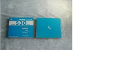
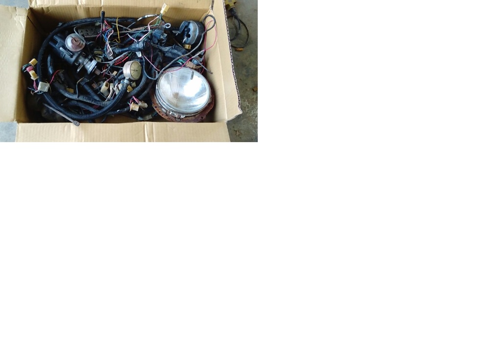
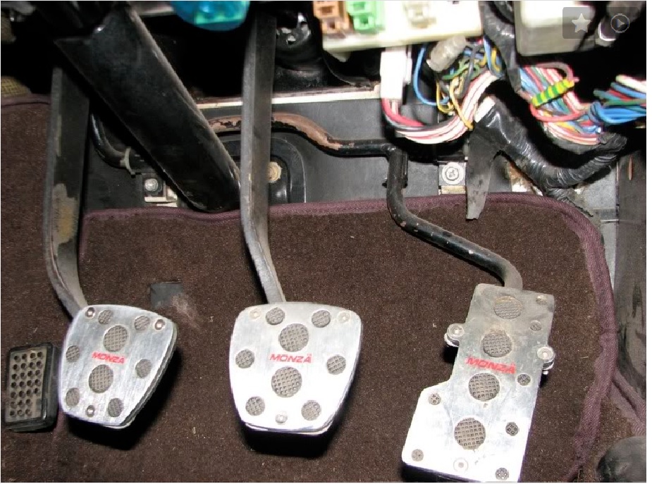
Anyone doing a RHD conversion? USDM import to UK or OZ? Got this in a box of parts from Japan. 50$ plus shipping. I will throw in a RHD speedo cable for an extra 10$ if you buy both.

-
-

.jpg.56f15d5503f40f7b7aa7998620530118.jpg)
.jpg.5a59c6cbf43009d715feca2e2ae74670.jpg)
.jpg.90e0085b7695db2e53bb7f7e42b86055.jpg)