Captain Obvious
Free Member
-
Joined
-
Last visited
Everything posted by Captain Obvious
-
 As Captain Obvious, I guess I just have to ask... You sure you don't just have the connectors swapped? Is it even possible. or are they keyed to only fit one way? I didn't look at any of the wiring diagrams to confirm, but I believe that all the populated locations do something. So just using the populated locations as a guide, I come up with this :
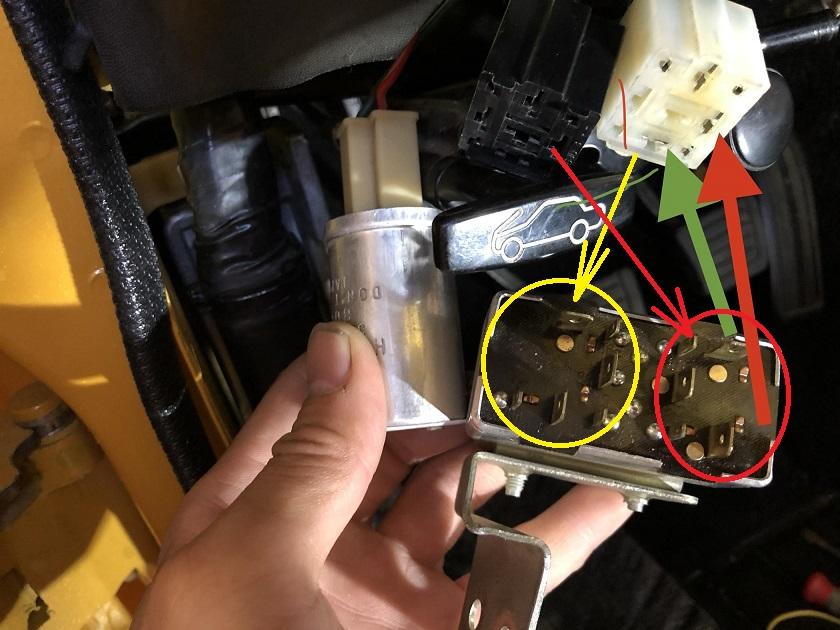
-
I don't think it's as simple as picking a 3K Ohm thermistor out of a catalog and tossing it in there. The 3K is the room temp resistance, but that's not the only important reading. You also have to know how it responds to temperature. @Dave WM If you had an environmental chamber, you could rig up some way to temporarily hold a test lead to the other side of your thermistor remains and plot it's temperature characteristics.
-
I just grabbed a pic of some random thermistor. I wanted something that had leads on it and a pic that wasn't so big that it filled the page. Don't try to read any engineering into my choice for that pic. But... It's a 4.7K from Vishay: https://www.vishay.com/docs/29049/ntcle100.pdf
-
I was thinking the same thing. I wonder if it was just measured at a different temperature, or if ZCD has used multiple different thermistors.
-
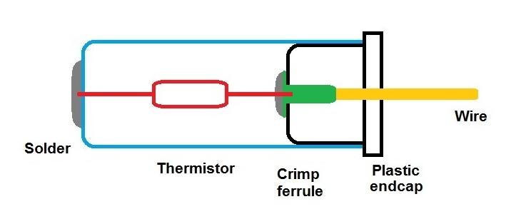
I updated the pic above to show more details about how I think the crimp ferrule is used to transition from device lead to wire.
-
Yeah, I'm thinking that inside that black cap there is a ferrule crimped onto the end of the yellow wire. That ferrule would be crimped onto the wire at one end and have a flat disk with a small hole in the other. Stick the thermistor lead through the hole and solder it to the disk. Transition from the semi-rigid thermistor lead to the flexible stranded wire. Of course, I've never even held one of these things in my grubby hands so it's all speculation and analysis from afar.
-
You ought to be able to de-solder the lead from the can and then just pull the plastic cap out with the thermistor along with it. (If the whole thing isn't too fragile by now...)
-
Dr.Dave, Yep... There's the other end! DaveWM, I assume there used to be some sort of discrete component in there, but honestly I don't know enough about thermistors to answer your good question about just a length of wire that changed it's resistance with temperature. I guess it's a possibility? Maybe? I think it used to look something like this and the thermistor turned to dust: I also don't think there is anything buried inside the plastic end cap. I think that's just a device to transition from the thermistor lead to the flexible wire.
-
SteveJ, thanks for putting the video on youtube for me. That worked. And Yarb, thanks for the video. So Dr. Dave, are you able to see the remains of the thermistor body down inside your outer housing? In this pic, you can see the solder blob on the outside where they made connection to the other sensor lead. You should be able to see some of that lead inside the case:
-
Yarb, I don't know if it's just me, but I couldn't get your video to work. It downloaded, but it was a blank screen. Probably a problem on my end, but can you do youtube instead of hosting it here on the forum?
-
Dr. Dave, Great photos of the failed original sensor. I did a little google searching on the internets for that part number (as I'm sure you did), and came up blank. I suspect that number is the part number for the ASSEMBLY, not just the thermistor. The thermistor itself is probably a small chicklet device with two leads on it. Just as a rough idea: Looks like they soldered one lead to the wire embedded in the black plastic cap, and then they slid the thing together making sure the other lead poked out a hole in the metal can. Then they clipped the other lead off and soldered that other lead to the can. So in the end, you've got a one wired device with the other connection coming back through the chassis mount. You pulled one lead out with the black plastic end cap, but there should be more to it. Either the rest of the device has turned to dust as a result of the heat, or may still be stuck down inside the can. You pic is too dark for me to see inside the can, but there is more still in there. All that said, I think your analysis about the locations and sizes of the holes might bear some additional scrutiny. It seems unlikely to me that after being submerged in the fuel tank for hours, being shaken around by driving, that the air bubbles would not have worked themselves out of the ZCD sensor, but who knows. And if that sensor is sitting in a little air pocket, it could certainly behave exactly like the problem you're seeing.
-
Sadly, I will not be making the trip this year either. For those of you who attend, please stay safe, and I hope it's a fantastic event!
-
The original reference to Darmok is from a Star Trek episode where they encountered a race that always spoke in metaphor. In that situation, you can understand the WORDS, but they really mean nothing unless you have a shared past experience. For example, you could ask "How is the weather?", and I could answer "Dave WM and Captain O riding in the Z." Haha!!!
-
Dave. Dave! Come back!! Dr. Dave asked you a question: Haha!! So Dr. Dave, I don't think there would be a lot to be learned from a post mortem on the dead one. The only really interesting thing would be to characterize the thermistor against a temperature curve, but if it's open circuit, that won't be possible. I guess there's a tiny but non-zero possibility that the open circuit break is somewhere I could see and kluge together long enough to take some measurements. There is also a tiny, but non-zero possibility that there might be a part number on the outside of the sensor? Up to you if you want to waste the dollar it would cost to mail it.
-
Dr. Dave using stone knives and bearskins.
-
So Dr. Dave, Can we drop back one last time... Is there any possible way your thermistor is NOT dunked in gasoline at half tank when the light comes on? I know you verified that the holes allow liquid to enter the sensor. Is there any possibility that the location of the holes is important? Stagnation perhaps? Does your old thermistor on your original fuel sender unit still work? If so, any thoughts on swapping the two and getting on with life? Want to send me some parts and I'll see what I can do with them?
-
Well that one is easy but you're sure pulling out the stops with the Andromeda Strain reference!! That was a fantastic movie. I saw that movie many moons ago (waves arm), and it scared the craps out of me. And to be honest, I remembered the basic plot and story, but I didn't remember the details of the bell clapper on the teletype. I had to go look that one up!
-
In agreement with everyone else. I don't see any reason you couldn't retorque. I will, however, say that I would not a retorque to change anything. In theory, your inner races have been (and still are) clamped tightly against the distance piece between them. In order to change the end play, you would need to either move one of the outer races closer together (which you should not be able to do) or shorten the distance piece. In theory, of course. Who knows what will happen in real life when you put the black iron pipe and the breaker bar on it!
-
Yup. I measured mine at approx. 5.4 cold. Maybe yours is a couple hundred milli-Ohms higher because you're in hot sunny FLA.
-
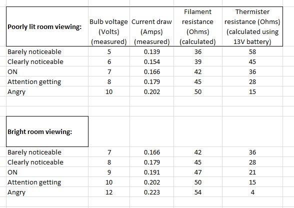
I got data. I applied voltage to a FUEL warning lamp indicator (red lens and all) and "analyzed" the brightness. I came up with the highly subjective brightness levels of: Barely noticeable Clearly noticeable ON Attention getting Angry I measured these values in both a "poorly lit room" and a "well lit room", and here's what I got. It's neat (geekwise) that you can clearly see the filament resistance increasing as the current (and temperature) goes up: It appears that what you really want is for the thermistor to work the way it's supposed to. Failing that, I would try maybe a 50 Ohm pot in series and see what happens? I'll leave it to Dave to calculate the power dissipation in the pot and determine if it's feasible.
-
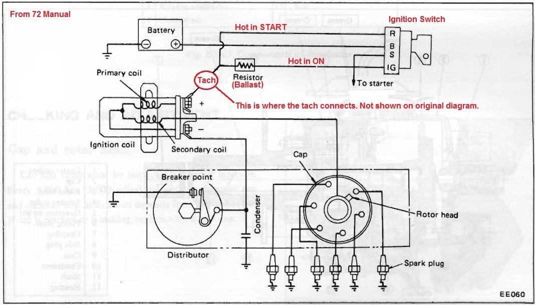
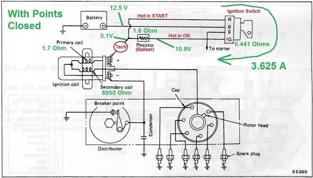
Well with the numbers you supplied*, everything looks fine to me. First off, you need to understand that the numbers you supplied were with the points closed. I don't know if you did that on purpose or not, but that's where you engine ended up the last time you shut it off. If the points were open, pretty much everything you measured would be full battery voltage instead of the readings you got. But with the points closed, here's some stuff you can infer from the readings you took: 1) You're pulling 3.625 Amps through your ballast resistor and into the coil primary. Seems completely reasonable to me. 2) (Assuming a loaded battery voltage of 12.5 Volts) You're losing about 1.6V worth of battery voltage in your ignition switch and the associated wiring. That means the total resistance of everything involved is just under a half an Ohm. That seems a little high to me, but for fifty year old wiring and maybe an original switch, it's probably expected. It won't prevent the car from running, but might be time to clean some connectors and replace the ignition switch. 3) You're dropping about half your ignition voltage across the ballast and about half across the coil. Based on the resistances you measured, that makes perfect sense. A little off, but perfect for a reality check. Putting all that info on the circuit diagram, it looks like this: As for the numbers on the coil with the engine running? You're trying to take a DC measurement on something that is not DC and you need to be careful about how you interpret those numbers. Assuming you're using some new fancy fangled meter, it's probably providing some sort of "averaging of the signal" it's trying to read. If that's the case, then those number look OK too. You're using a DC scale to average a pulse width modulated waveform, and the "averages" look reasonable. * Except the coil secondary. I'm assuming you're reading the scale incorrectly and (as SteveJ mentioned earlier) it's actually 8.95K Ohms, not 8.95 Ohms. I think your meter is auto-ranging and you're not seeing the tiny "K" somewhere on the scale.
-
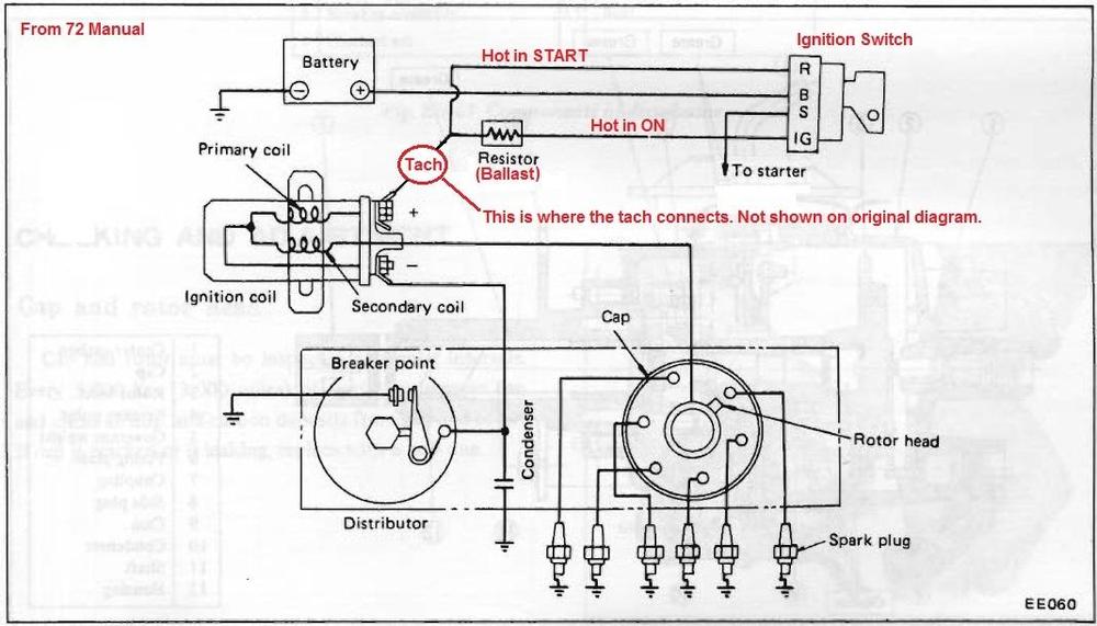
Assuming yours is the same as 72, here's how it should be wired:
-
I can help with that tomorrow. I will push current through one of those little bulbs until it starts to "noticeably" glow. The current measured at that point will enable me to extrapolate how low the sender resistance needs to go in order to light the bulb. I had previously measured the bulb current (directly connected to a power supply) at about 230 mA. So that's "full bright". In order to reach that level, the sender unit would have to drop to 0.0 Ohms. Clearly the current at which the bulb is "noticeable" will be less than that.
-
Well I'm no help on the sensor resistance front. I pulled my HVAC bezel off and measured the resistance. Open circuit. Thinking that maybe I had a bad wire or connector somewhere, I pulled my little access hatch off in the rear and measured it right at the tank. Open circuit. I know the rest of the system works because if I ground the bulb wire back at the tank, the lamp comes on, but without a working sender, it'll never come on. I don't usually run the tank down so far as to really care, but my warning sender is fubar.
-
Hahahaha!!!!!