


Captain Obvious
Free Member
-
Joined
-
Last visited
Everything posted by Captain Obvious
-
 Yarb, My pleasure. Pochie45566, so as mentioned above... You can't just slap a BCDD blockoff plate on there and call it a day. Doesn't work. And your A/F ratio is 11.5 at 1750 RPM under no load? I'm no expert on the subject, but that's something that probably needs some attention as well.
 -
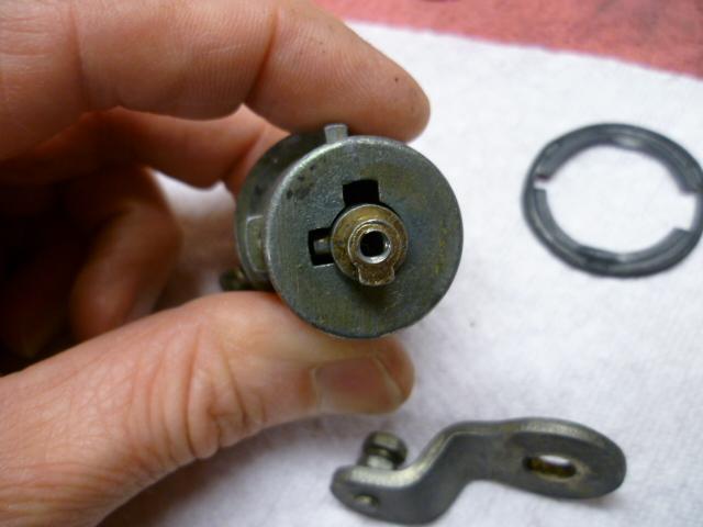
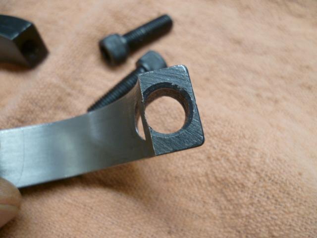
That would be really cool if you can just swap the actuation arms and drop it in. I know there have been people looking for replacements for that hatch lock. There needs to be some sort of non-round feature between the arm and lock cylinder so the arm doesn't slip on the post. Here's how it works for the stock one:
-
Mine does that too. I suspect your fuel check valve on the output side of your fuel pump doesn't hold pressure overnight. It holds for some shorter period of time (seconds, minutes, hours?) but not enough hours for it to have fuel pressure for that first cold start of the day. To test that theory, you can force your fuel pump to run and build pressure before you try to start the key. Couple different ways to accomplish that depending on the year, but the one failsafe version is to disconnect the small spade connector to the starter solenoid and then turn the key to "START". You should hear the fuel pump run. And I bet you'll be able to hear the difference when the pressure has reached normal. After you're convinced the pressure is up to where it should be, reconnect the starter and then start the car.
-
Glad you got it solved. Too bad the bolt stub didn't come out easily, but they never do for me either.
-
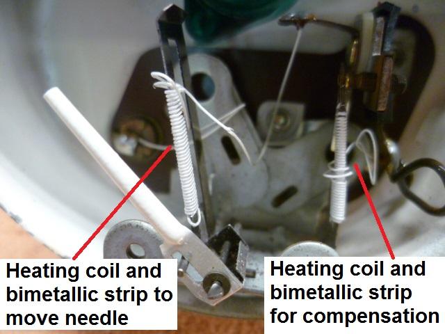
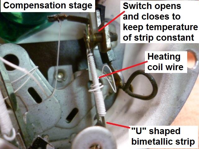
OK, I will convert this stuff to it's own thread when I get a few more minutes to make it read right. In the meantime.... I have more pics. Here's a pic of one of the gauges. You can see the two different heating coils wrapped around two different "U" shaped bimetallic strips. Interesting to note that internets research indicates that "U" shape is part of the compensation as well. The concept is that the unheated side will compensate some for changes in ambient temperature. "They say" it doesn't get rid of all of the temperature based effects, but it helps some. Between that "U" shape and the compensation stage, the gauges seem to be really stable. So this is an example of the compensated gauge with the two stages: And here's a closer-upper pic of the compensation stage showing it's parts: The switch opens and closes to keep the temperature of the compensation strip at a constant temperature (ave). If you put a Voltmeter on the sender unit, you'll see that it isn't a steady voltage, but is instead a square wave.
-
I don't consider it cheating on your first piece.. And even on piece 1000, if you aren't making some special pitch or tight fitting thread spec, it still isn't cheating. I don't remember... Is your lathe equipped to cut metric threads? Glad you're making chips!
-
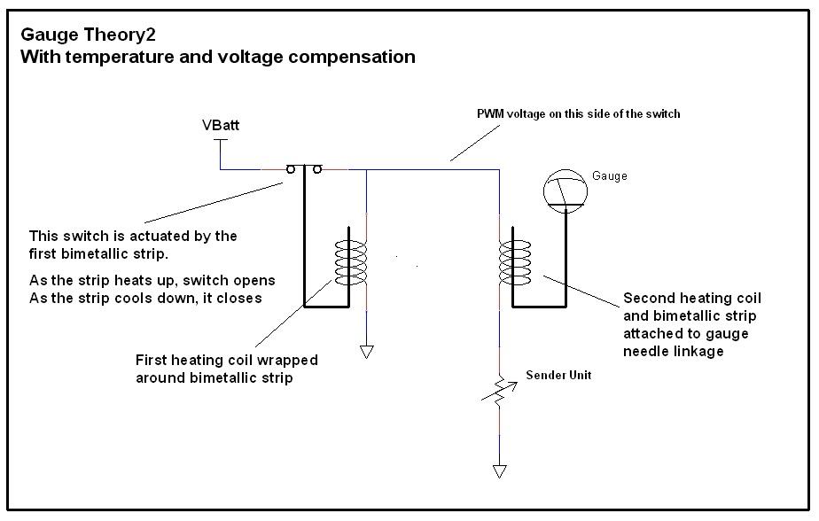
LOL. I'm pretty much out of TV shows too. I get it. There are two "stages" to the compensated gauge. One of those stages is he simple gauge we already talked about above. The other stage is the compensating or regulating stage. It's job is to compensate for changes in ambient temperature and varying system voltage. The compensation stage consists of another heating coil wrapped around another bimetallic strip. This bimetallic strip forms an electrical switch such that when the strip heats up, it breaks contact. And when it cools down, it re-establishes contact. The trick is, that it makes and breaks contact to it's own power source and the power source for the simple gauge stage. The result is that this second strip/heating coil combo will make and break the power source such that it will always achieve the same average temperature. Of course the temperature is rising and falling some, making and breaking connection, but the AVERAGE is always the same. Colder day? Power to the compensation strip will have to be on longer to reach the temp that bends the strip to the point where it breaks the switch connection. Hot day? Just the opposite. Power will be on for a shorter time. Low system voltage? Again, power will have to be connected longer in order to heat the strip to the desired temperature,. And conversely, if the voltage is higher, it'll take less time. The result is that the compensation stage creates an ON/OFF/ON/OFF pulse train whose duty cycle and frequency will change depending on the ambient temperature and system voltage. This effectively creates a voltage source that will always supply a constant amount of POWER to the gauge system under all conditions. Clear as mud? Connect that constant power source to the simple gauge from above, and you have this: If you put your key in and turn it to "ON" you should see the gauges start to rise. Don't start the car. Just pick a needle and watch carefully. You'll see the needle start to rise, but probably before it reaches it's final position, it'll pause... Then start rising again. Then pause again. This will continue until it finally reaches it's final position. And even then, if you watch carefully, you'll see the needle actually wiggles a tiny bit. This effect can most easily be seen with a needle that's moving well above minimum like a full tank of gas. That pausing and wiggling is the compensation stage opening and closing.
-
Yup! And they're often well lubed. And sometimes they even turn blue!
-
Nice. So you turned the rod OD down to accept a die for making the thread? Or did you actually cut (they call it "single point") the threads on the lathe? I'm guessing you used a die. Single pointing threads is not something you typically do on your first piece ever.
-
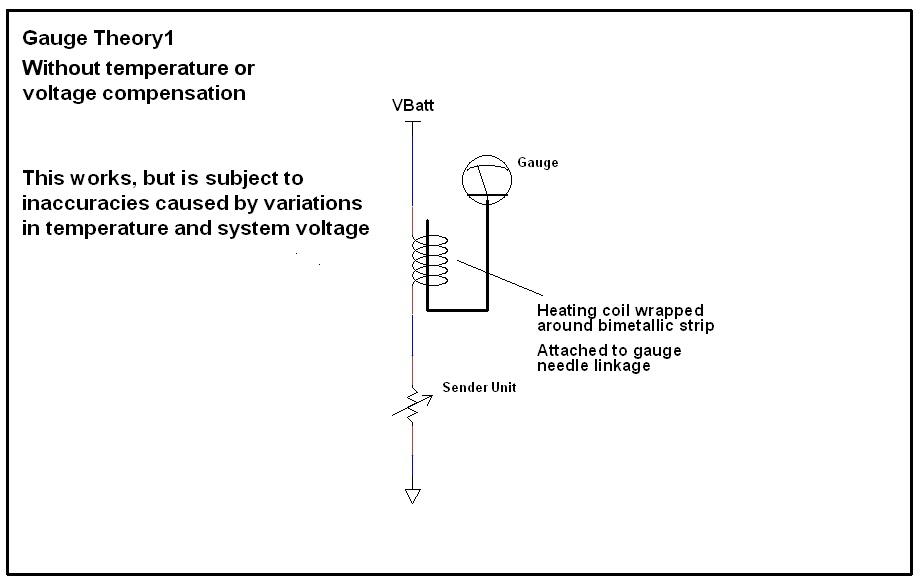
OK, I promised to describe how the gauges work... Not sure it should be here in this thread, or if I should start a new thread for this. I'll put this here for now, but if people think it should be separate let me know and I'll start a new specific thread about gauge theory. So in order to understand how the gauge system works, I think it would be a little easier to first understand how they DON'T work. I think everyone already has a good handle on this simple system, but it's an important place to start. Here's a pic of a simple (uncompensated) gauge design. Wrap a heating coil around a bimetallic strip and mechanically attach that strip to the linkage of a gauge needle. Flow current through that heating coil and to a sender unit who's resistance reflects the level of whatever you're trying to measure (temp, oil, fuel, whatever). As the resistance of the sender unit changes, the current through the heating coil changes and that changes how hot the bi-metallic strip gets. The lower the sender resistance, the higher the current. The higher the current, the hotter the bimetallic strip gets The hotter the strip, the more the needle moves. Here's a pic: This simple uncompensated gauge system does "work", but it is subject to a few real-world outside influences that can affect the accuracy: First, since the whole thing works on the temperature of the bimetallic strip, the gauge will read differently on a hot day than on a cold day. And second, since the gauges are powered by the battery system of the car, changes in that system voltage will affect the gauge readings. The gauges would read differently sitting with the engine off than they would with the engine spinning at 3000 RPM when the alternator has kicked up the voltage a bunch. The system voltage can vary from about 12V to over 14V and the gauge readings would change as the voltage varied. So the basic gauge system above sorta works, but these two real-wold effects are undesirable. If the above basic gauge system makes sense, I'll get into how they compensate for those two real-world effects.
-
LOL. Maybe he's polishing? Or waxing?
-
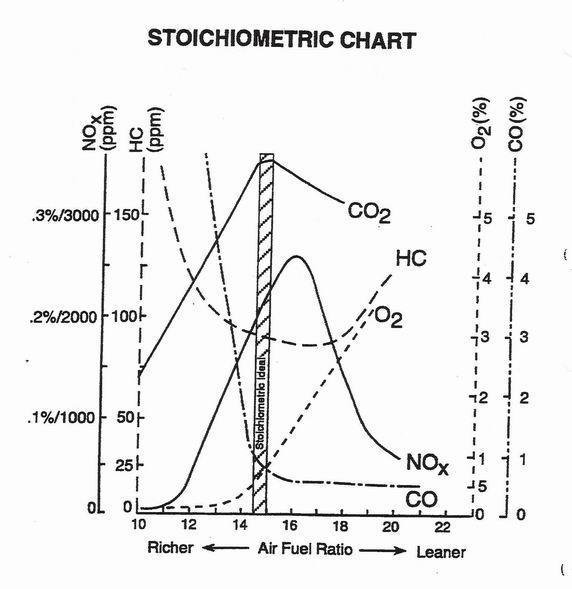
Here's a pic showing some general emissions levels with respect to mixture ratio: I don't know who created that diagram, so I can't credit the author. I do know that Hoover @240260280 posted it a couple years ago. Thanks Blue!
-
Glad you're doing better. If you're running rich now, it might be because of that messed up needle (at least at idle). For the cost of a pair, I'd replace them. That one has clearly seen better days.
-
Awesome! I'm so happy!! Stainless can be a PITA sometimes depending on the grade and what you're trying to do with it. Run into any issues there? And I agree with the above. Pics of the little fella!!
-
You're right. That does look pretty close. If you bought that can three years ago, it's probably the older formulation. I don't know if it was intentional or an oversight, but the newer cans (from that same source) are different than the old cans.
-
Only in jest! My local Z buddy here painted a block a couple years ago with that custom blue can from CA Datsun. Looked great compared to the stock color (when compared to other things like the harmonic balancer from that engine). Then he bought a second can about a year ago to do a second block and now it's a lot darker that it used to be. Doesn't match the stock color very well. Too dark and not enough green. sfm6s524, It's hard to tell from just a pic, but yours looks like the darker batch. There might be some overspray on the plate between the block and trans for a comparison?
-
I hate people. Glad the Z is looking like it wasn't all that serious.
-
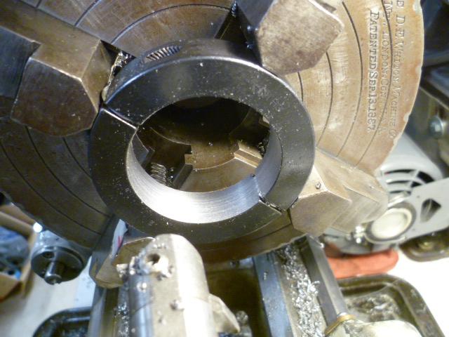
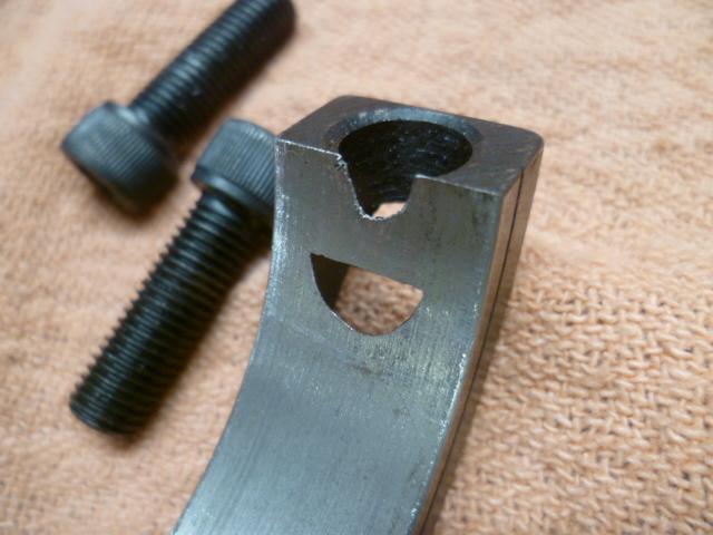
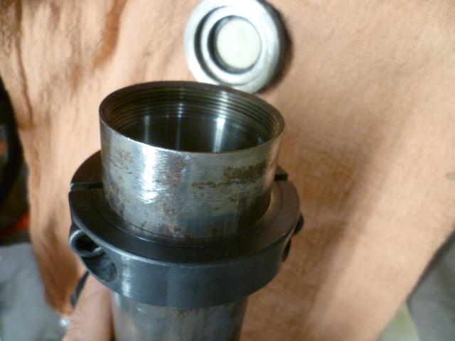
So I had mentioned above that if you are going to do the split collar perch support concept, you need to pay attention to the collar size. This is what happens when you impulse buy 2" collars for your 280Z because you assumed they were the right size. They aren't. The 2" collars are too small and won't fit around the 55mm (2.165) diameter 280Z tubes: Not wanting to admit defeat, I aligned the collars and chucked them up in the lathe and bored them out to fit the 280 strut tubes. Looked like this on the lathe: In the end, I had to take off so much material that they got a little Swiss-cheesie, but good enough for the temporary use that I plan for them. Would have been better to start out with 2 1/8 collars instead of 2". I would still have had to bore them out some, but not as much and they wouldn't be quite so holy: But in the end, here's what the bored out collar looks like on the 280 tube. Should be "good enough." :

-
Will do! Thanks for the support!
-
That one needle looks like it's seen better days. I don't know if that's contributing to your issues, but it takes a really small change at idle to make a big difference in the idle mixture. Those dents and other signs of mishandling of that one needle would concern me.
-
AK260, thanks much for the additional info. I'll look into those to see what I can find on my side of the water. And on a related note... The 74 FSM says the strut tubes OD is 2 inches (50.8mm). After that, (in later years manuals, they greatly reduced the amount of detail about the suspension members. Starting in 75, they stopped listing the OD of the tubes as well as much of the info about the corner springs. Why is this related? Because all the tubes I have here are from various years of 280's and they are all 55mm OD (2.165 in), not 50.8mm. I'm assuming this was part of the beefing up of the suspension stuff that occurred for the 280. Unfortunately none of this is documented in the manuals, but it needs to be taken into account when looking for things like those strut tube bellows / gaiters. It also matters when you're trying to size split collars to use as temporary spring perches to hold the springs in place for locating. If you buy 2" collars, they won't fit:

-
Yeah... Don't do that. Haha! ! Good luck with the project and here's hoping it all goes smooth.
-
-
M6 x 1.0 is used extensively all over the car, and while I did not look up that bolt specifically, I believe that's what it is. As for the official pilot drill size necessary, I'd have to look into that. There are rules for metric taps (that I never committed to memory), but it would be easier for me to instead just see what size drill bit fits snug into the threaded hole of a couple M6 x 1.0 hex nuts and just use that. Edit - You made me look... My crib notes says I use a 3/16 (.1875) drill for my pilot when tapping M6 x 1.0. It's probably a little undersize according to the rules, but that's how I roll.
-
I think the oil pressure on the mechanical gauge looks fine. Seems like an electrical issue with the dash gauge.


