


Captain Obvious
Free Member
-
Joined
-
Last visited
Everything posted by Captain Obvious
-
 I believe it's simply ID and OD. The small change might seem immaterial, but I bet it's quite significant if you look at it in percentages.
 -
Well there's lots of ways that a booster could go bad, but that's one of them. If you vacuum the booster down and then stop pulling it down, it should hold that vacuum. I've gone to junkyards and pressed the brakes on a car that's been there for who knows how long, and sometimes you'll still get a whoosh or two because the booster still had vacuum in it. Check valve still worked and the valve built into the booster didn't leak. That said, another common way for a booster to go bad is for it to leak through the big diaphragm (like there's a crack in it or something). The reason I bring that up is because it will act almost like a working one on the bench with one detail... If you pump down a working booster and put a gauge on the engine side (the front side) it should hold that vacuum while not pressed. It sounds like yours does that. But as you actuate the booster, it should not lose much vacuum on the front side. It should stay pretty much the same. Then when you release the booster rod, it should bleed from the front side to the back side, and that's when you should see the vacuum change on the front side. Not on "pedal down", but on "pedal up". If you see all of your vacuum disappear immediately on "pedal down", then you may have a hole in the diaphragm.
-
Call me skeptical, but I'd be very surprised to hear that they painted the valve covers. Maybe, by some wild stretch.... Maybe someone could convince me that the very early valve covers got some paint, but by the time they got to the NISSAN OHC covers? I'm very skeptical. Frankie, Is the inside painted? Can you use the same solvent you used on the outside and see if anything comes off the inside? I do know (from unfortunate yellowing and peeling experience) that they clear coated the later valve covers. I don't know if they did that all along, but by the end, they were.
-
Oh yeah, I got caught up and forgot to tie that back to your question... The POINT is that every time you actuate the booster, you'll be "using up" some of the vacuum on the back side of the booster. And then when you stop actuating it and everything equalizes, it won't return to the same vacuum because you've vented some of it off. Every time you actuate it, you'll lose some of that vacuum.
-
The power brake booster basically works like this... 1) With no foot on the pedal, apply equal vacuum to both sides of a the big diaphragm. 2) Then when the pedal is pressed, allow some atmospheric air (from the car's interior) into the cavity on the rear side of the diaphragm (the side you sit on). 3) Allowing some atmospheric air into the rear side reduces the vacuum on rear cavity and allows the vacuum on the FRONT side to help pull the diaphragm towards the front of the car. 4) The further down you press the pedal, the more atmospheric air is allowed into the rear side and the more assistance you get from the vacuum on the front side 5) Then when you let off the brake, the vacuums equalize between both sides of the diaphragm again. Not that anyone asked.... * I know that it's pushed by the higher pressure and not "pulled" by the lower pressure, but I think it's easier to describe as being pulled.
-
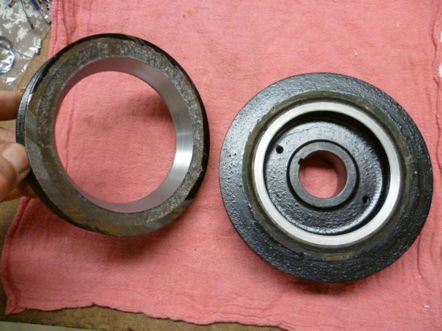
I'm looking at some old pics of when I cut one of the pulleys off a two-pulley harmonic balancer. (Academic project on a damaged balancer.) Don't remember if I ever posted these in the past, but here's a couple pics: The point is... I'm wondering if the nut you purchased is going to work. First, the corners of the hex need to be small enough to fit inside the front oil seal. You could remove the front seal if you need to (since you're probably going to replace it anyway). Second, you'll need enough length on the nut to a) engage the key on the crank, and b) still have enough length sticking out of the front cover to get a turning tool onto it. If the front cover is completely off the motor then neither of those trouble spots apply, but if the front cover is still installed, I'm thinking things might not work out.

-
You gonna be OK? Need anything?
-
Thanks for the tag Jim, but what are webers? Never heard of it.
-
Oh, OK.... Suuuuuuurrrrre it is.
-
Haha! I'm just looking at those three pieces of input there and I have no idea what's going on. The first two are completely contradictory, and the third is orthogonal.
-
Charles, Cool. If it doesn't fit and you can't fix it with a file, let me know. If it's not hardened, I can modify it to fit. Wayne, I was thinking the same thing! So where does the rubber junction come in on the damper? Is the center portion isolated from everything else. or is there something you could machine into a "wrench attachment point"?
-
Ummmmm. OK?
-
Hmmm. If I have appropriate sized stock, I could make that. Does it have to be hex on the outside? Would something with just two flats on opposing sides work? Or square? You wouldn't be able to use a socket on it. You'd need to use a large open end. Would that be good enough? I'm thinking that since the application is to unstick a motor, you might be putting considerable torque on it and a hex would be better. But thought I would ask to see what you thought.
-
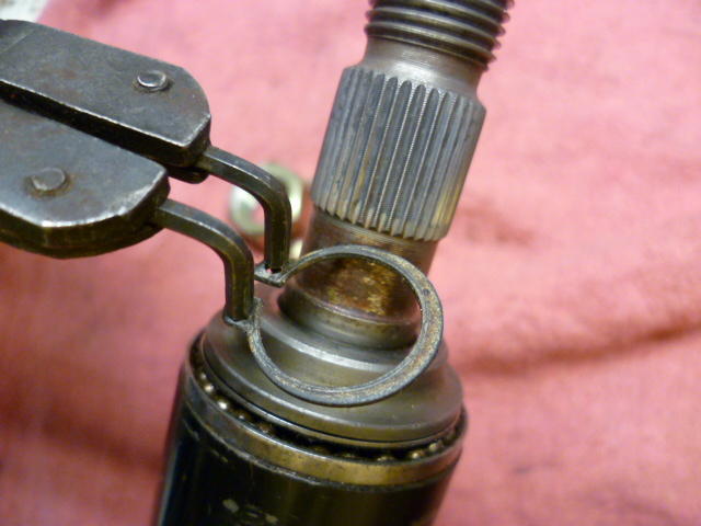
I found it easy to remove the clip, but yes... You should unload it first. Doesn't take a lot of force. (Alone) I found the easiest way was to place the column against the ground and grab the column housing (outside) with one hand and press down against the ground, thereby compressing the spring a little. Been a while since I've been in there, but I probably braced the whole thing against a hip or something? Anyway, at that point you can remove the clip as soon as it's unloaded. Of course, if you have a helper with a second pair of hands, it's even easier. Some pics because we all like pics:

-
Yes, I am confirming that there should be no binding between the needle and the nozzle, regardless of piston position. I'm thinking that the mixing and matching didn't do good things for you. If the carb body still has it's nubbies, then you need to run the original dome and piston. If the nubbies are busted off, then you'll have to do the alignment manually, so in theory you could mix parts together if you do it right. And yes... Nubbies. It's in the manual.
-
Boing boing boing boing. I see that the cabin fever has really started to take hold. So I've taken a steering column apart down to it's molecular level, so if you have questions about that, let me know. I may have pics.
-
The three screw round tops are supposed to have little conical shaped alignment pin nubbies on the top of the carb body that establish alignment with the suction chamber. Sometimes they are broken off as part of a carb rebuild process. Are you alignment nubbies intact, or are they broken off? If they are broken off, you'll need to manually align the suction chambers. If your alignment posts are NOT broken off, then I would suggest that maybe you swapped the suction chamber covers between the two carbs. Any ideas about the probability that happened?
-
Ummm. For me, it would take more than one finger?
-
Nice bikes guys! I don't have any pics of my old crop duster in electronic form. I'm sure I've got a bunch on film squirreled away in a box somewhere. If I turn something up, I'll post up a pic. It was a rocket in it's time. I think the only thing faster was that wacky Kawasaki triple thing.
-
Haha! Thanks for the insights. And I hope it's not all placebo effect. At least the oil cleanliness couldn't have been placebo! If this were a "build" instead of a "refresh", I'd probably go that route. Maybe on the next one!
-
My build buddy bought one. I don't know if they have different "quality" levels, but it was the bottom of the line. We used it once and after that unbelievably frustrating and dangerous episode of thread galling and smashed knuckles trying to turn the handle... He told me it was my decision, I could either make it better, or throw the piece of shite out. I replaced the threaded rod with some all thread I had laying around, made all the wallowed out oval holes round again, and added additional lock-nuts all over the place to keep things where they belonged. We've subsequently used it to remove and install three motors and it's waaaaaaaay better. Sorry I don't have any pics.
-
The Duke!!
-
Well don't beat yourself up about it. The differences in length are really not much. In fact, I'm really wondering why they didn't standardize on the same length bolt in all four positions in the first place. I'm guessing there was a miscalculation or design change somewhere along the way that they worked around using the two different lengths. I wasn't there when they designed it. but I don't see any functional reason for it. And hope you can find some enjoyable way to pass the layover time. No junkyards in the area?
-
Mine was a Suzuki, but, me too! And me too! Suzuki T-350 with Wisecos!!
-
I've heard good things about those total seals. If I were doing a more in-depth rebuild on this motor, I would have considered those. But for this motor, I'm just honing and throwing stock rings back in. How did they work for you? You like the way it turned out? And yes, I'm with you. I would still stagger the gaps too. Even though it seems to matter even less. Haha!

