Captain Obvious
Free Member
-
Joined
-
Last visited
Everything posted by Captain Obvious
-
 Haha!! Good thinking!
 -
Got it. Hoover sent me some used condoms along with the other stuff in the care package. They look good, so I'll use them again.
-
Yup. That's the one I was going to buy before I decided I would try my hand at building a better mousetrap. Cheapest I found was on ebay for just under $40 shipped. So it may depend on how much Summit wants for shipping.
-
!! Actually Mr.J, you're either 0% wrong or 100% wrong. There is no timer in the defroster circuit. But there IS a timer in the 77 seat belt warning circuit. So it depends on which circuit you're talking about. Or we could split the difference and you can join The Half club. It's exclusive.
-
Glad to hear that I nailed it. Woot. And BTW... From a distance with no meter measurements, I've diagnosed and identified a problem with your car that you have unable to fix yourself, and the reaction is "kudos, you're half wrong". I've identified the problem that has been confusing you to the point where you needed to ask for help, and your reaction is to make sure that I know I wasn't 100% correct when I said "Your defogger indicator bulb IS burned out" because the REAL story is "Your defogger bulb is not installed". Well maybe it's just me, but that kind of response makes it difficult to want to help in the future. Just like last time with your other thread. So feel free to now spend a whole bunch of words* telling me why my reaction is wrong. Or just don't. And keep it in mind for the future instead. * A whoooooolle bunch. And make sure you include one or two words that make mere mortals reach for their dictionary because they don't have as awesome as a vocabulary as you do.
-
I agree. I've not actually used those, but knowing what I know now about the "overlapping band" style, I believe those pliers would be easier to use with a higher probability of success. The modification I mentioned earlier about removing excess material from my overlapping band would essentially make them more like that pliers style. I think if I removed enough of the band such that there was no overlap, it would be a lot better. Limits the range it works for, but I'm not planning to do a whole bunch of this. You certainly don't want to buy or make a tapered collar for every size piston in the world.
-
How it's made - NASCAR episode. https://www.youtube.com/watch?v=P3_UQcnHB1E - At approx. 3:50, they use a tapered ring that looks just like mine. Might be the spark that made me make my tool...
-
Haha!! Since I have two of these band styles, I may try modifying one (the one that isn't borrowed) to make it a little easier to use and work a little better. And I thankfully found the sharp edge burr on that thing before it found me. So stupid. For the fifteen second quick wipe across a band sander is all it would take to dress that burr off. That kind of stuff drives me nuts. So if you do spin one of those up in the winter, let me know if you want any input when the project comes around.
-
Namerow, Funny you ask that. I first saw that kind of tapered ring compressor tool on TV. Don't remember exactly what show it was, but probably something like "How It's Made". which is one I watch a lot. I took a quick look through some of the episodes I could find on youtube and didn't find exactly the one I remember, but I did find all sorts of piston installation techniques. Here's some quick clips with some examples: https://www.youtube.com/watch?v=0clb7aTYn5o - At approx. 2:15, they use a tapered ring, and the neat thing is that due to the way they attach the piston to the crank first, their tapered ring has a slot in it so they can slip it out of the way past the rod after the cylinder has been slipped over the piston, https://www.youtube.com/watch?v=Ub0xP9tUzr8 - At approx. 1:30 they use a funky pliers style clamp in one hand while pushing the piston into place with the other. Not a tapered ring, but pretty cool. Looks like it works great. https://www.youtube.com/watch?v=GUo7qOVycvs - At approx. 3:25 they use a tapered collar style. I can't remember where I first saw that tapered collar style, but it was a production facility. I think I saw a whole bank of pistons being inserted at once through multiple tapered holes in a jig. I couldn't find that one, but that's what I remember. So IMHO, the whole drawback to the tapered ring style is that it only works for one piston diameter. If you're only planning to do one or two sizes most of the time, it would be worth it, but if you have no idea what's coming in the door next week, you'd probably just get to be an expert with the spring steel band style.
-
I have a lathe and I'm not afraid to use it. So about the band style... I actually have two of them. First one I am borrowing from the super-generous hoover @240260280. It uses an infinitely adjustable friction based holding "latch" to keep the size you crank it to. I have a hard time with it though because the latch is quite stiff and it takes a lot of force to crank it down and a lot of force to release the latch. I find it cumbersome and needs three hands to use. The second one I have uses a ratchet-gear based latch. It's easy to turn, but the problem is I get it tight to the piston, and I really need ONE MORE CLICK. But I can't GET one more click. So when I relax on the tightener, the clamp relaxes a tiny bit and I think that's why I kept snagging oil rings on the deck. And the other problem with both of them is the area where the spring band overlaps. It's never completely round. I was thinking I could cut off some of the extra metal band to take care of that, but wasn't sure if it would be that much better. Anyway, after all the futzing with both band style tools, I remembered seeing the tapered style and figured I would give that a try. It took three hours to make, and if I can get six straight shots out of it without worrying about snagging an oil ring, then I'll be satisfied.
-
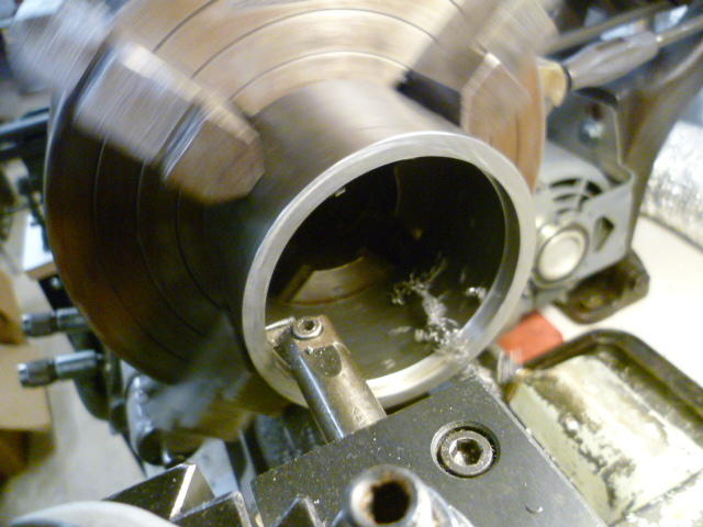
Well nobody get too envious yet. I've not actually tried it for real yet. I'll be sure to keep everyone posted if it actually works. And a note about the tool... I made that one, but I didn't come up with the idea. I've seen them used in videos in the past, and they are available for purchase cheap in the sizes we would use for our engines. So, why would I go through the trouble of making one when I could just buy one for $40? The answer is I wanted one made out of steel, and I also wanted to put a little lip on the bottom side to fit into the chamfer recess on the block deck. The commercial ones have a flat bottom where they contact the block, but what I made has a little ridge on the underside that I'm hoping will make it even easier for the rings to make the transition from the tool into the block. Like I said, I'll let everyone know if it works, or was a time wasting fail. Dave, I did not freehand the taper. I used the compound slide on the lathe. It's got maybe a three inch working throw there, and I only needed two. The most difficult part of the whole job was getting a good polished finish what won't snag a ring. I don't have carbide boring tools, so had to use HSS. And because of that, I had to run very slowly. And I still smoked the cutting oil. It took a while to hit on a tool grind geometry that would cut and not "tear", but I finally did. But even so, there was still a lot of hand polishing required to remove the tool marks. The REAL way to do this would be to cut on the lathe a little undersize, have it heat treated, and then final grind to size. I'm not really setup for that. And (for the foreseeable future), I only need to get twelve shots out of the tool. Six for me, and six for my buddies build.
-
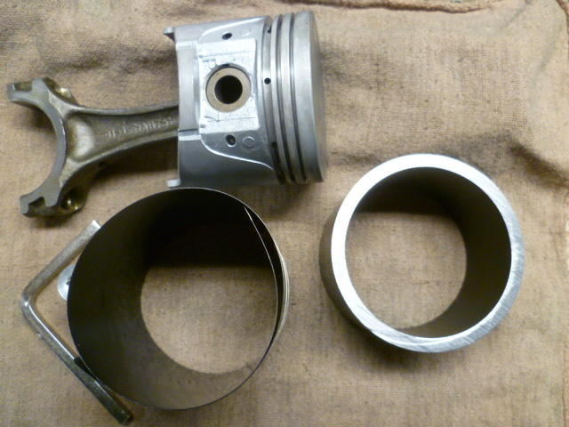
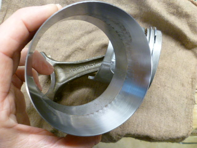
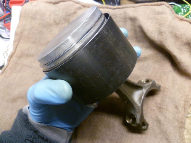
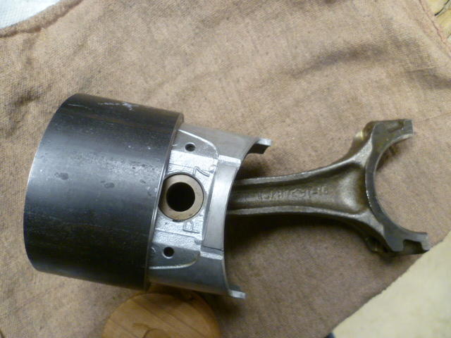
Yeah, I remember our discussions about that and I wanted to let you know where I am at this point... I only put one piston back in the block, and it was a PITA. Like you, I found the band style compressor to be very finicky. I'm assuming it gets better with experience, but it took me three tries to get the first piston back in without catching one of the oil rings on the block deck. Third time it snicked into position, but I'm just not happy with the compressor. I've actually got two of them and I'm not completely enamored with either of them. So I decided to try something different and made myself a tapered installation ring tool. Bought some steel tubing of appropriate size. Here's what I started with, Band tool on left, and thick wall tubing on the right: I chucked the tubing up in the lathe and bored it out to be a precision fit over the piston: And then I tapered one end with a gradual taper and polished everything up so the rings slide easy: The concept is you can slip a fully ringed piston into it and the rings will compress as you push the piston down the tapered section: And once the rings are all compressed, the theory is that I can just slip the pistons into the bores from here: And why does this pertain to ring gaps? Because since you're pushing straight down, the gap positions don't migrate. They stay where you put them. So I'm jumping the gun here a little since I haven't actually used it to put a piston into the block yet, but it worked great on the bench. What could possibly go wrong? go wrong? go wrong?
-
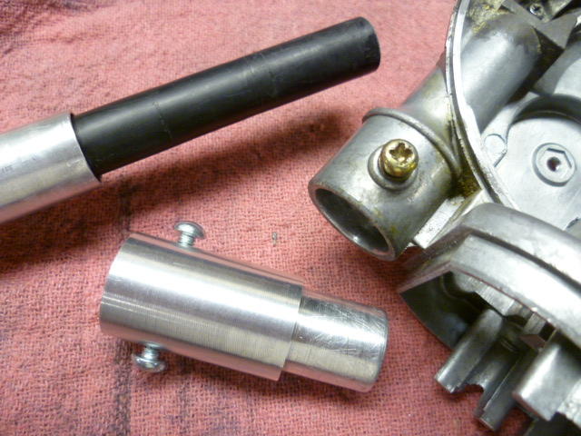
Well it wasn't a total loss, but it was one of those project steps which should have taken fifteen seconds turned into an hour of work. After the BFI removal, I cleaned everything up and made an "adapto-matic" extension to replace the original cut off portion and put the length back to where it should be. My aluminum adapter: Goop it up inside with silicone and put it back together: \ I actually made two adapters, but I don't remember exactly why. Either I needed to change diameters to use the mast from a different antenna, or it was simply "I cut it twice and it's still too short". Been too long to remember that detail, but in the end, the mast looked like this and it worked great: So like so many projects, it wasn't a total loss, but it took way longer than it should have because of unforeseen surprises.


-
Q - "How is the (defrost) indicator connected to the Timer?" A - It's not. Q - "Why does the Defog switch operate the heating elements, but not the indicator?" A - Probably because the defog indicator bulb is burned out. So how can those answers be correct despite all of your intensive research? It sounds to me like there are two faults... 1) Your defogger indicator bulb IS burned out, and 2) You have the indicator bulbs for the defogger indicator and fasten seat belts indicators swapped. Without being able to take any measurements from here, that's the simplest I got. Does your blue "FASTEN SEAT BELTS" warning lamp come on when you turn the ignition to "ON"?
-
I had one that was so corroded that I simply could not get the mast out of the lower housing. I finally resorted to the brute force and ignorance method. Now that I've done that once and know what I'm dealing with, I might be able to come up with something a little less destructive next time (if there ever is a next time). But since I had no idea what I was doing, I cut it off and mangled the shite out of it until it came out. :


-
Right. That's what I'm doing. The oil expander ring does not contact the cylinder walls at all, so there's no sealing implications there at all. I do suspect, however, that (because of friction) the bottom rings may not rotate at all, or if they do, I suspect they will all rotate together as a set. So my read is that it's important to get the two lowest ring gaps 180 out of phase, and the expander at 90 between those two. And I wouldn't be surprised if they always stayed that way.
-
Zed Head, I looked into the ring rotation a little, and you're right. Pretty much everyone says they rotate unless they're pinned in place. So knowing that, it seems to make the importance of the clocking of the ring gaps less important. One opinion I dug up said that it makes it easier to compress the rings evenly and install the pistons if the gaps are staggered. Another opinion was that it mattered in the initial start first few seconds of the initial start and then doesn't matter at all after that. In any event, I guess I'll keep doing what I'm doing, but won't get anal about nailing my 45 degrees exactly every time.
-
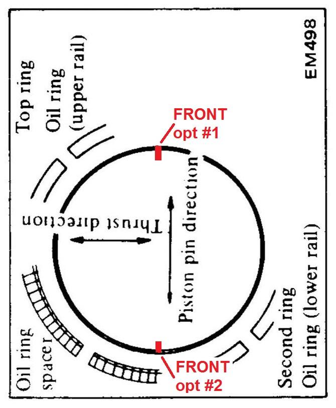
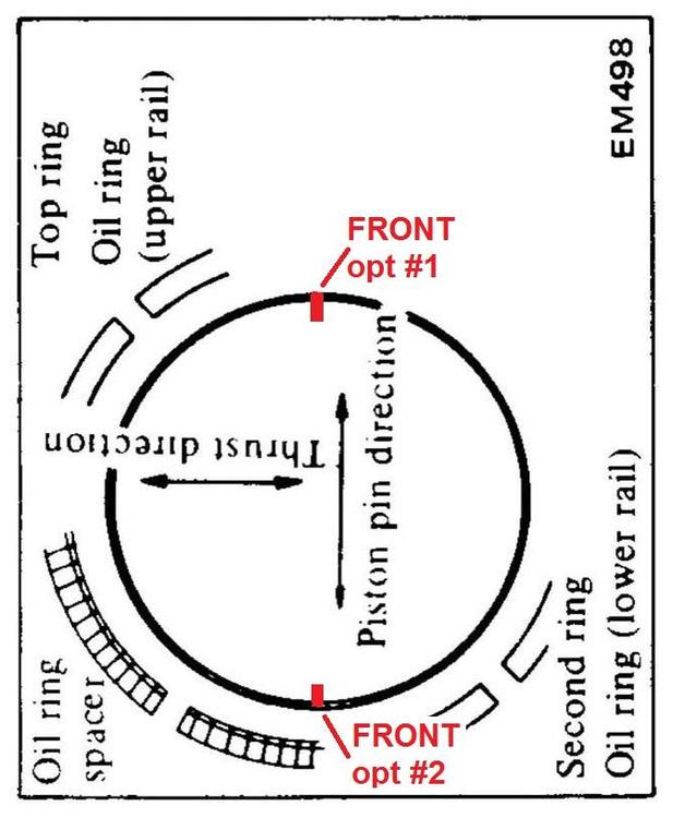
I find the pictures from all the FSM's a little confusion because they don't put the FRONT notch up top. All those FSM manual pics have the piston pin running side-to-side instead of top-to-bottom, and I just find it confusing because I want the notch at the top. To get the FRONT notch at the 12:00 position, you have to rotate that sketch. And also interesting to note that they do not specify "FRONT" at all. Just the piston pin direction. Seems it really doesn't matter which is FRONT. You could rotate that sketch either direction and it would still be right. I rotated it and put on the two possible FRONT notch locations: Either of those FRONT locations would follow the "rules". The FSM shows the pressure rings all at 4:30 and 10:30, but I don't see any reason why 1:30 or 7:30 would be any different.
-
My understanding is that the starting offset was to maximize the length of the path between compression and non-compression. The longer the labyrinth, the less leakage. And staggering the gaps +180, -180, +180, -180 is the best you can do. And while some things are designed to "walk", I don't think the rings are one of them. I believe the gaps are intended to stay where you put them. But all of this is why I'm hoping some of the engine builder experts will chime in. I have all my rings on pistons but haven't put the pistons back in the block yet. I still have time to completely change all my gap locations if someone throws their body in front of what I'm planning.
-
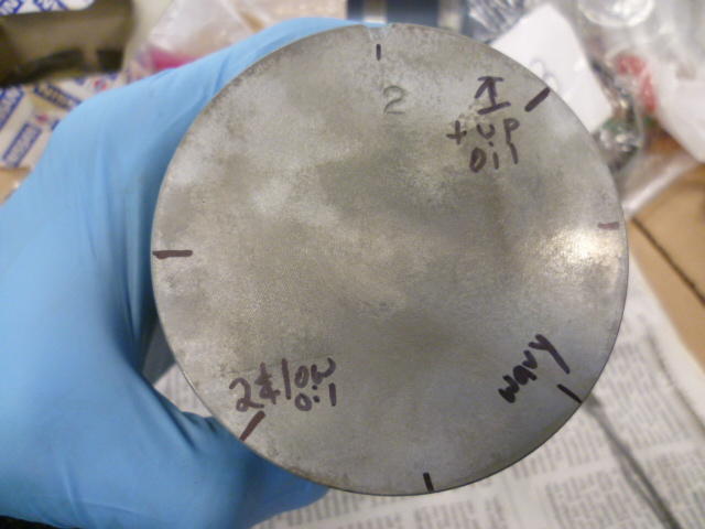
Good timing. I'm messing with the same thing right now. I didn't find "clear cut positions" anywhere either, but I believe the overarching gap position rules go like this: 1) All the gaps should be at a 45 degree angle away from the piston pin center 2) The 4th (bottom) ring and second ring gaps should both be in the same as position 3) The 3rd ring and top ring gaps should be 180 degrees away from bottom and 2nd 4) oil wavy ring gap (expander) should be 90 degrees from all the other rings Some additional rules, not specifically related to gaps, but since we're talking about rings, it's probably appropriate to mention them here: 5) Put the wavy expander in first and make sure the split portion is titts down, like an "M". 6) The thin 3rd and 4th rings do not have a top/bottom. Doesn't matter. 7) 2nd and top rings DO have a top and bottom and make sure you have identified that and get them on correctly. So, interpreting those rules... Put the waver scraper ring on first. Pick a position for the gap. The rule is "45 degrees from piston pin", so you have four choices - 1:30, 4:30, 7:30, or 10:30. And then once you have picked a position for the expander, the rest of the positions should fall into place. An example: Put your wavy expander at 4:30. This mean that all your other gaps must be at 1:30 and 7:30. Fourth and second being the same at either 1:30 or 7:30, but third and first must be opposite. I looked closely at my block and tried to figure out where the rings originally were from the factory and then when I put the new rings in, I tried to put them somewhere ELSE this time. Figuring I would "even things out". Not sure it makes much difference, but that's my plan. Before I put the rings on, I marked the piston tops with sharpie to make it easier for my little brain to keep things straight while moving the gaps around. I'll clean the sharpie off after the pistons are installed. Looks like this: However, all that said, please note that I'm no expert in such matters and give a little time for other people to throw their bodies in front of advice before you put all your pistons in. I'd like to give other people some time to tell me just how wrong I am before you go and repeat mistakes that I've made.
-
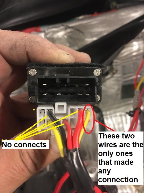
Yeah, that one was a real bonus! I was cleaning that connector with the 100% expectation that it wouldn't have any effect, but (roll eyes) I had to perform due diligence and clean it before I moved on to more difficult solutions. It was just the right thing to do. Bonus!!! Sometimes you win one! I guess I'll keep that new sender lock ring and sealing O-ring in a box on the shelf! Haha!! And buy a lottery ticket?
-
Exactly. That's what it sounded like to me, but I'm having a hard time believing that he got two senders with the same blob in the same location.
-
No, I think if it were resistance in the wires (and connectors), it would do what you said... Inaccurate through the whole range. SOUNDS like the sender unit has a dead spot below 1/3 tank, but I'm having trouble explaining the exact same behavior with two different senders. I'm also having trouble explaining how bending the arm could fix this. (But full disclosure, I've never messed with the sender units.)
-
-