Captain Obvious
Free Member
-
Joined
-
Last visited
Everything posted by Captain Obvious
-
 No, I think if it were resistance in the wires (and connectors), it would do what you said... Inaccurate through the whole range. SOUNDS like the sender unit has a dead spot below 1/3 tank, but I'm having trouble explaining the exact same behavior with two different senders. I'm also having trouble explaining how bending the arm could fix this. (But full disclosure, I've never messed with the sender units.)
 -
-
-
Chase, So your gas gauge works fine for all situations except when the tank is about 1/3 full? If that's the case, then I'm having a hard time coming up with any answer other than a problem with the sender unit. I know you replaced that and it didn't fix the problem though, right? Does the new replacement act just like the old original sender unit?
-
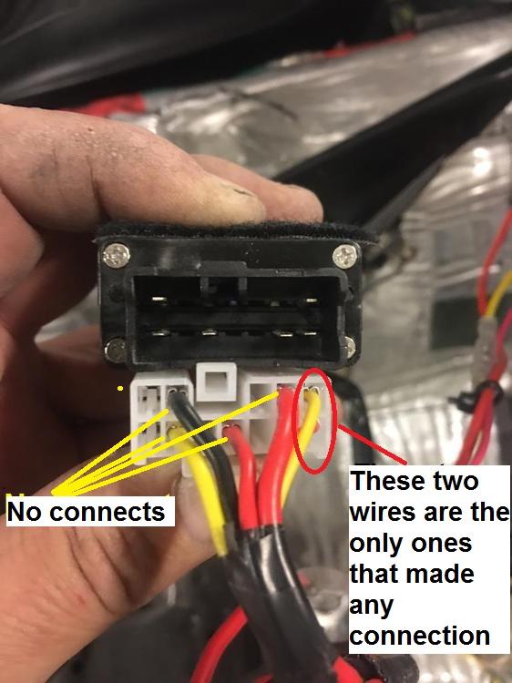
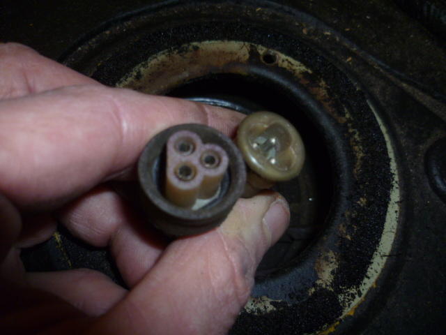
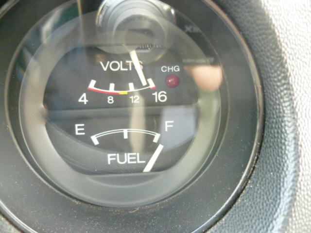
I filled up my gas tank yesterday for the first time since cleaning the connector pair at the sender unit, and guess what!!!!?? My gas gauge now reads significantly higher than it used to before cleaning that connector. Here's a full tank now. It used to read at about 7/8 full (even when full), but now it looks a whole lot better: So for me, cleaning this connector made a big improvement: I may still pull the sender unit out of the tank for inspection, but the priority just dropped down on the list a bunch!
-
-
So that looks OK to me (now that I can see it). I put in a section for "Mid-year changes" in the 260 folder just to see how that would look. I guess the first major question to debate is... Would it be better sorted by item specific changes (like seat rails), or as a design timeline (most likely by year)?
-
I can't really tell what the wiki style would look like without an example, so I put in a couple years just as a test. I don't know if anyone else can see that categories I put in. Says it needs to be approved by a moderator.
-
Man that looks fantastic. I sure wish I had something like that in my car. I don't drive it in the middle of winter (when there's salt on the roads), but there's still a significant portion of time before and after that when I would really enjoy seat heaters. I either need warm air blowing out of the dash vents, or I need to stick one hand at a time under a leg to warm them up. As of right now, I still haven't figured out an easy way to get hot air out the dash vents, and sticking fingers under a leg against cold vinyl just doesn't do it for me.
-
I think the idea is great, but the implementation is clearly up for debate. How about a simple description of "differences from the previous year" and then if there are questions or requests for pics about something specific, they can be added. Just to illustrate things, I tried to pick something that everyone knows about from each year: 72 240: Changed from the four screw round top carbs to the three screw and routed water into the carbs to heat the nozzles 73 240: First year for the flat-top carbs 74 260: Changed the seat rails to a new design First year for shock absorber mounted bumpers 75 280: This is the first year for the fuel injection 76 280: Increased the number of parking brake ratchet teeth Added weather strip rubber along tops of doors 77 280: Changed the seat rails to a new design New sheet metal stampings pretty much everywhere 78 280: Redesigned ignition module which allowed removal of the ballast resistor I'm thinking just keep filling in differences as stuff comes up?
-
My pleasure. Glad to help. And a hug would be nice too. I'm a lumberjack and I'm OK. So I was a little pressed for time earlier when I posted that diagram and didn't have time to talk about the use of flashing the high beams here in the US. First of all, if we here were to flash the high beams, we would just pull back on the HI/LO stalk twice in rapid succession. More modern cars have a "make-before-break" type of switch now, but back when the Z's were new, you just pulled the stalk twice. And even before that type of control, the homegrown stuff here often used a foot switch operated by your left foot. You would stomp the switch twice quickly. As for the meanings... Just like where you are, there are several different meanings to the flash. I don't know if there are regional differences in the USA, but where I come from: Quick flash at an oncoming driver can mean "I just passed by something that you might like to know about and you should pay attention." Things like debris on the road, animals along the side of the road, police ahead. That sort of thing. A quick flash at an oncoming driver may also be "You have your high beams on and it bothers me. Please put your low beams on." That may be quickly followed by a longer flash if the desired response is not achieved. A quick flash at an intersection means "You go ahead. I'll wait." A flash from behind usually means "Move over, you're driving too slow." The length of the flash is usually commensurate to how frustrated the guy in the rear is. A quick flash on a multi-lane highway after you have been passed by a faster vehicle means "You are safely beyond me and can tuck back into my lane if you wish." Most often used by trucks, but sometimes I'll give trucks that sign even if I'm driving in a car.
-
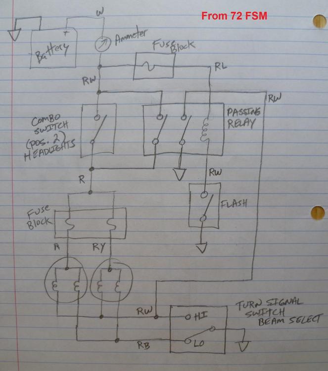
Here's what the 72 system (with the FLASH feature) looks like. Other than the addition of the FLASH / PASS button and the passing relay, it's pretty much the same thing they used in my 77. Point being.... I'm assuming that all the years in between are also the same, including yours. You can see that the pair of headlight fuses are not hot at all times, but are only hot when the headlights are turned on. You can also see that the headlight system has no interaction with the ignition switch at all, so the headlights can be turned on regardless of the key position. Same thing goes for the FLASH system. Also interesting to note that when you push the FLASH button, it will turn on the high beam filaments. Full stop. Doesn't matter if the headlight switch is on or not. Doesn't matter if the lights are already on in LO beam. Even if the low beams are already on, it will power both filaments at the same time while the FLASH button is being pressed. Hand drawn in all it's glory: Hope that helps!
-
The US cars don't have the flash button, so I'm operating without a net, but your diagram does not look right to me. In the US, the headlight fuses are not hot at all times as you have shown. The OFF-ON switch is between the battery and the fuse box. The fuses are only hot when the headlights are turned on. In addition to that, with what you have drawn, the ONLY way to get the high beams to light up is to push the flash button. I think there's stuff wrong... The newest thing I have here is the 72 manual still shows the FLASH relay, and the basic system is pretty much the same as the US with the exception that the flash relay is wired in parallel with the rest of the system and will turn on the high beams even when the headlights are not on. Would it help if I were to sketch up the 72 system?
-
Yeah, your fuel gauge looks like it reacts the same as mine. Always too low. I haven't done anything else with mine (since I cleaned up the connector right at the sender unit), but I fully expect my issue is inside the tank. Murphy's law pretty much demands it. That Z hasn't come back around on my work sheet yet. I've got all sort of other car work to catch up on. Today I changed the plugs on a V6 Kluger. Including the three invisible ones in the back... That's no fun. As for the bike "teaching moment"... Very nice! Thankfully, tis but a scratch!
-
Just like Ty did! https://www.youtube.com/watch?v=kBxuVQ6lrAM
-
Here's some of the stuff I read on the internet. Some threads from HybridZ: https://forums.hybridz.org/topic/51104-differences-between-the-240z-and-280z-rear-control-arms/ https://forums.hybridz.org/topic/64548-stock-control-arm-length/
-
Haha! One thing at a time, right? So do you have a signal generator? I bet you could just use a 12V square wave to test the tach on the bench. It might require the flyback spike from the coil primary as a trigger, or not. It might work fine with a clean 12V square.
-
I read on the internet that the later control arms got beefier. Thicker steel and maybe some additional gussets here and there for strength. I don't know if the form-fit-function changed when they got beefier, but if not, even though they are different, they may still be "interchangeable".
-
Yeah, that's not an option then. So how about pics... Can you take some pics of the carbs you do have? Do you have any documentation that came along with them? Also, earlier you said "both dampers are working to make them rise slow and drop fast." - How did you test the dampers?
-
I looked here for a spare tach (aka not installed in my car) and I couldn't find one. I know I had one some time ago, but I also remember that I sold one to a deserving desperate forum member at some point in the past. Maybe that was my only spare? If I had one, I'm sure I could come up with a way to test it on the bench. (Easy for me to say, right? ) Anyone want to send me a 280 tach for investigative purposes? Haha!!
-
Same here. I thought I had a schematic around here somewhere, but I can't find anything. I'll keep looking.
-
The damper is a "transitional" device to temporarily slow the rise of the piston when there is a rapid increase in the air speed through the venturi. This has the effect of richening up the mixture for a short period of time. The damper does nothing to affect the piston position during steady state conditions. If you're already running lean on transition, then running without a damper will only make that worse. @RS02 , You've got so much stuff going on that I find it hard to get a "baseline" from which to operate. I don't know anything about "Rebello modified" carbs, but my (non-expert) suspicion is if they bored out the throat and changed the venturi area, it will have the effect of leaning out the mixture at the same airflow. So unless you're pulling in more air to make use of the new larger venturi area, then things are not going to work out well. A thinner needle may help mitigate that situation, but I wonder if those carbs were more intended for flat out WOT (track) performance more than street driving. I agree with the sentiment above that it would be a good idea to drop back to a set of "normal" SU's and see what happens. Just so many variables...
-
I'm a little skeptical about changes like that from someone who may or may not know what they are really doing. It's admittedly unfair for me to question his fix while I have nothing else to propose, but his explanation certainly didn't satisfy me. As zKars pointed out above, there is a 2200 Ohm resistor in series with the tach on the 280's. Another 5 Ohms added to that 2200 won't do squat. Makes me question the mod. When I get a chance, I'll look to see if I have a loose tach around here.
-
Welcome to old Z ownership.
-
Once you have shorted out the 5 Ohm resistor, it really doesn't matter if you leave it there or clip it out. However, I have no idea as to the validity of that "fix". Without doing some reverse engineering I cannot provide any input into what that modification does or if it's really a good idea or not. The guy in that video seemed confident in it, but I'm not confident in his confidence. He said something about "running the numbers" and "that resistor in there reduces the voltage"... Well, without seeing a schematic, I'm not sure at all what that means. Might be harmless, might not. Is this a common thing that a lot of people mess with? I might have a spare tach around here somewhere...