


Captain Obvious
Free Member
-
Joined
-
Last visited
Everything posted by Captain Obvious
-
 I was thinking the same thing... For wasted spark, you don't need any cam position info at all. And for sequential firing, you don't really need a "good" cam sensor. You get the real "timing" info from the crank wheel. The only thing you are doing with the distributor mounted sensor (cam sensor) for is go/no-go to differentiate whether you're on TDC compression or TDC exhaust. (As an academic aside) I even wonder if you have an O2 sensor, maybe you could even tell the difference between compression and exhaust strokes by analyzing the exhaust gas composition. When you first turn the key and crank the car, it's 50/50 right?
 -
With the way the original system works, you cannot simply remove or cap off those connections. In addition to feeding the AAR's idle-up function, they also are for the PCV system. The AAR idle-up system CAN be deleted if you feel you don't need the idle-up feature when your engine is cold, but deletion of the PCV system is more problematic There are two hoses involved that complete a "loop" to pass air through the crankcase. One of them connects from the engine block (below the thermostat housing) to the PCV valve. The other one is the hose that connects the top of the valve cover to the intake duct tube. As part of the way the Bosch L-Jet system works is by measuring the air flowing into that system and metering the fuel accordingly. If you start capping off or venting those hoses, it'll play havoc with your fuel mixtures. You need both of those hoses, or neither. And if you run neither, you need to be willing to accept the issues that come with that.
-
I bet you could make a cheap and dirty version of that ring from a thick piece of rubber to take up the gap. Or buy a silicone tube with the right ID and OD and cut a sliver donut off it. It's not structural, you just need to fill up the gap.
-
I used one from a Ford Taurus. Details here: https://www.classiczcars.com/forums/topic/57826-afm-intake-boot-tube-replacement-from-ford-taurus/
-
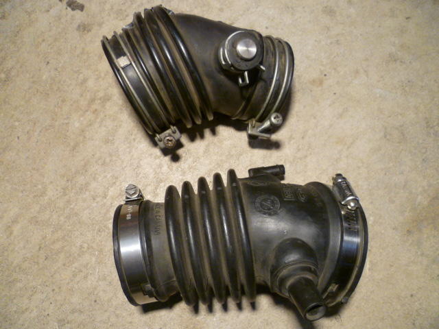
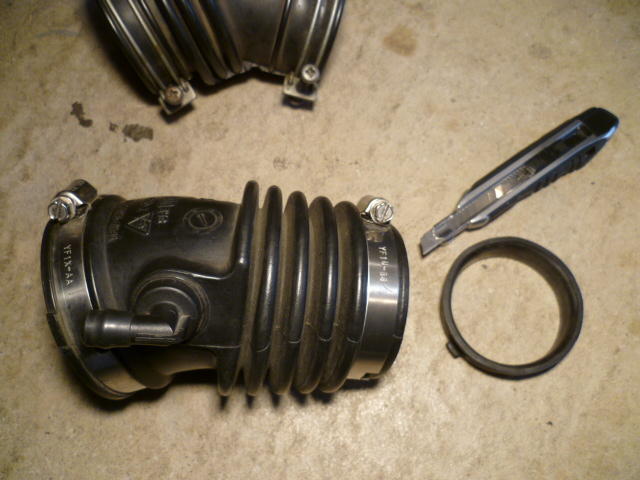
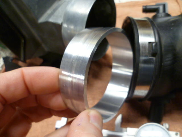
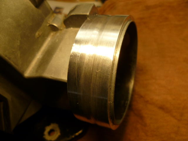
One of my off season projects for this year was to replace my sketchy looking intake duct tube between the AFM and the throttle body. I couldn't see any cracks all the way through, but it's just a matter of time. I know there are aftermarket repros available, but I've always kept my eyes open for other cars that had air intake tract hoses that looked similar to the 280Z. With that in mind, and my never ending quest to find cheap ubiquitous replacements for OEM parts, I nabbed this on off a 2002 Ford Taurus: Here it is compared to the stock connector. The angle is almost perfect, but there are some issues. First, it's a little too long and second, the big end (AFM end) is too big: Taking care of the length is simple. Quick work with the razor knife to remove about a half inch from the small end where the hose clamp was and then put the hose clamp back on a little further up: Second problem... The big end is a little too big. The AFM is 2.75 diameter, but the Taurus hose is 3" diameter: So (on the lathe) I made a spacer ring out of aluminum: Put a little sealer on the joint and press the spacer into place. Now I've got an AFM with a 3 inch outlet instead of the original 2 3/4 inches: Put everything back on the car and it looks like this. Cheap, ubiquitous, and although it isn't stock, it doesn't stand out like blue silicone tubes. One more step in having every molecule of air going through the AFM instead of around it:


-
The theory is that if you use poly on both the front and rear of the T/C rods, you run the risk of snapping the rods from the stress. There are a number of threads here (and on other forums) on the topic, and I believe there are even pics of T/C rods that have snapped off.
-
Oh, and fuzzy memory with no pics, but my trick to getting the ring back on with the column in the car was to wedge something (screwdriver probably) into the upper U-joint area next to the steering coupler donut area to force the steering shaft towards the driver's seat far enough to get the ring back on. IIRC, you can loosen the coupler bolts and compress that lower spring enough to get the ring back on. I try not to "put my back into it" anymore. Bad stuff happens.
-
I know you already took care of your column without taking the bearings out, but just so they exist somewhere, here's my photos from the job. Note that if you are going to take the bearings out of the column, you'll obviously need to have the column out of the car and disassembled. Tap the bearings out of the housing if you dare. I used a long chunk of brass rod because that's what I had laying around and used that to tap the bearings out from the far end. The bearings are press fits into the column tube, but it's not a very tight press. Work your way around the perimeter tapping gently and you can walk them out. Here's the long brass rod that I used: Tapping around the perimeter, walk the bearings "gently" out of the tube: Then once you get the bearing assy out, you can pop the retaining ring and lose the balls: There are thirty balls in the bearings so you can count what you have to make sure you didn't drop any: I've been through this job a couple times now and I have added additional balls to the bearings. Not necessary, but I like the feel. I think it tightens things up a tiny bit. Originally there are thirty balls and I usually add one on each end. @Sean240Z added two balls to his and he really likes the way that turned out as well. So now that you're already done and the pictures were late to the party.... Let me know if there are any questions.


-
Parts look beautiful! Only comment... Many people don't recommend poly/poly for the T/C rods. I've heard (read on the internet) that a combo of poly and rubber is better and that's what I run on my car.
-
-
I suspect that your PO thought "well, green is ground, right?" Seems a bit of a leap, but that's all I got.
-
Problem is that tape on the handwheels prevents changes from accidental bumpage but doesn't do anything about the play in the leadscrew threads. Even with the handwheels stationary, the table can still move in X or Y by the amount of backlash in the leadscrews. That's where gib locks would come in. They lock the table regardless of how much backlash there is in the screws. I've added gib locks to a couple machines in my past that didn't have any. Looks like you have plenty of room to add them. Next time you have the whole table off the machine? In the meantime, If you're not chattering and the ease of cut seems fine, lets hope your OK without any locks.
-
I'm not sure if it would be more accurate than using a co-ax, but that technique works too. The most important thing is to lock the X and Y directions down after you get it positioned properly. I took another look at your pics and I don't see gib lock screws. Do you not have that feature? PITA, but you could always just tighten up the gib adjustment screws during the boring operation. Hate to do that though...
-
Dave, I haven't looked at the design of the ignition modules to see if they reference either side to chassis ground. My assumption is that neither side would be tied to hard to ground in the module. That assumption is based on the twisted-pair nature if the pickup wiring. They are trying to reduce the loop area with the twisted pair and it would completely defeat that purpose if they would tie one side to ground in multiple locations. My assumption without any reverse engineering is that the pickup inputs are not galvanically isolated (with a transformer or something), but they may feed some sort of floating input differential amp at the input stage of the module. If that's the case, tying one side to ground might not cause it to malfunction, but it certainly isn't necessary or desired.
-
Nice work. Some input below: There is play in the spindle bearings, there is play in the feed leadscrews, and once you start putting forces on stuff, everything bends and flexes and squirms. Even steel. That's why it's all really "made of rubber". You're pushing a hardened bearing shell with rounded corners into a hole. The rest of the system will squirm around to make it fit when you start putting pressure on it. Best thing you could do would be to use the co-ax to indicate the center of the original hole and then lock down both the X and Y travel leadscrews (I'm assuming you have gib lock screws on those?) before you start the boring operation. And I know you can't do this because of the set-up, but the less you have the spindle sticking out below the head, the better. The more it sticks out, the flimsier it gets. About that 4mm distance measurement of the wall thickness... That's not what's really important. What you really care about is that the center-line of the two shafts are in the right locations. I know you're interpolating that using the resultant wall thickness, but of course it would be better to measure the centers of the holes. Also, of course, if you get the new hole in the exact same center as the original smaller hole, you don't even have to measure it. You'll be spot on.
-
About a thousandth total runout? Kinda hard to tell because the indicator is buzzing around at such a high spindle speed. Usually when I'm doing something like that I disconnect the spindle drive completely and just rotate it by hand to find the high and low spots. Might be nice to know where the high and low are. Would help you determine if the runout is in the tool, the spindle, or just random mounting variation. You work with what you got, but MT3 aren't known to be the most accurate tool in the drawer.
-
I got an 83 2+2 parts car for sale cheap. I know this isn't the classified forum, but thought I would throw that out there.
Nice. You sure do have a long chang! Do you have any fly cutters. Seems your diameter adjustment could be made a littler easier, and no welding required. Usually used for facing a flat surface (like a head mating surface), but with the right cutter grind and geometry, I don't see any reason you couldn't use one to bore your hole:
Glad to help. Hope the project goes smooth.
And... The smaller red and black wires leading deeper into the tach are what makes the gauge needle move. I can tell you more about that if there are problems, but I'm hoping it just works and we don't have to.
Red is +12. Black is ground. Green is speed input.* White is gauge illumination lamps. *Note that I don't know what kind of signal the tach is expecting, but the green wire is where it should occur.
From those pics, I believe the black wire is ground side for power. Can you take the brass hex standoffs off and get a shot of the back side of the board? Is there enough slack in the tether wires connecting the board to the mechanical portion to spin the board over and get a straight on shot?
Maybe. Can you post a pic of the other side of that tach board? I can probably tell you which ones are power and ground.
Agreed. Repair looks fully functional. Might want to use something to pot that wire into place so you don't bump it or catch it on something and pull more of the PCB trace off the board. Hot glue as mentioned above, or an epoxy blob or two.


Important Information
By using this site, you agree to our Privacy Policy and Guidelines. We have placed cookies on your device to help make this website better. You can adjust your cookie settings, otherwise we'll assume you're okay to continue.