


Captain Obvious
Free Member
-
Joined
-
Last visited
Everything posted by Captain Obvious
-
 Oh, I thought you said it had just one bulb - "It looks like there is a little lightbulb in the right side of the display" So if there are multiple light sources, then that would remove the need for a shutter. Just turn on a source for each "layer". I took a quick look at the wiring diagram and the only thing that display connects to is the warning module you mentioned above. There is a dedicated harness that runs between the two (and only between the two). So, now the question(s) becomes... "Are there any smarts in that little display box, or is it simply a slave output bulb box for the amplifier module?" Haha!! Troubleshooting remotely from a distance on something I've never seen with my own two eyes. I don't have a clue! LOL. Wiring diagram indicates there's a black wire. If you assume that's "ground", can you Ohm out light bulbs or LED's to the other wires that don't go to the switch? You should be able to easily identify an incandescent or LED. (LOL easy for me to say from my distance, right?) And if they're LED's that would remove the necessity for a colored filter over incandescent bulbs. I bet that's what it is. But I've missed every guess so far though!
 -
Cool! So it's a light pipe! I was completely wrong. Not EL at all! You shine the light on the edge of the glass and it will refract when it hits the obstacles (the dots). You see the dots because of that. So how does it switch between the different displays? Some kind of small slit shutter between the bulb and the layers? Shutter moves across the different layers somehow?
-
@dutchzcarguy Well just the fact that it's multi-color unfortunately makes the system more complicated. So I've never seen one of these with my own two eyes, but simply from that era in time, the technology is probably vacuum fluorescent or plasma. Although it could be nixie-tube (neon) as you mentioned before. But I'm not sure if you can do multi-color with cold cathode like that.. My guess is that it it's VF. So I punched that part number you mentioned into the web and found one on ebay: And you're right. Could be a problem with the little display module itself in the dash cluster, or it could be a problem with the control module. Or any of the associated connections that make the system work.
-
Not exactly sure what the above means, but I took a couple seconds of looking on-line to come up with some examples of what it's supposed to look like maybe? From >> http://xenonzcar.com/s130/warninglamps.html Are those what it's supposed to look like if it's working? Is it really multi-color like that?
-
That's why I tried to get you today. I'm worried about you. I know you're super busy, but give me a ring when you get a chance. How much time do they give you between classes?
-
Well that would be perfect. If I need a dial engraved, I'll pay you to do it. I don't have anything in my shop that's CNC. In fact, I think all my machines are older than I am.
-
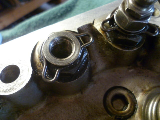
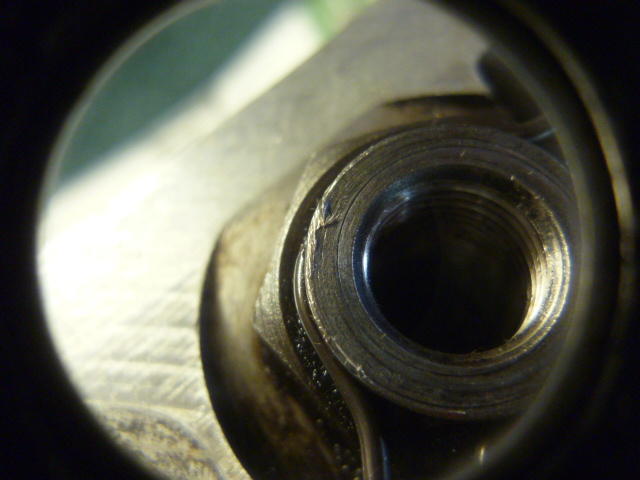
Right. The jam nuts should be pretty much finger tight until the last small amount of turn. The one I had with that burr would get slowly and gradually tighter to the point where I was sure it was tight enough, but it didn't reach that torque in the same way as the others. The torque didn't rise rapidly like the others. That was on my busted cam motor. After that whole debacle, I was going over that head in pretty heavy detail just looking for other issues. So that wasn't what made my adjuster come loose that one time, but I was just thinking if you were going in again for anything, it's something to keep in mind.
-
I've seen some small CNC versions. There have been projects that have crossed my path that made me wish I had something like that!
-
I'll absolutely give you a high-five! With the current exchange rate, does that work out to a high-seven and a half or something by the time it gets to you? I love the crisp body line down the whole side. Especially where bodywork often muddies it out over the rear wheel arches. Looks great!
-
I dug through my pics and found some of the burrs I was talking about. I'm guessing they were caused by wrench slips: Burr from PO had been pinched under the lock nut:
-
Yeah, I kept looking at Jim's disk and thinking "I've seen that somewhere before". It's not Tron's disk and I couldn't find anything Klingon that looks similar.
-
I had a similar occurrence once. Adjusted the valves and took it around the block. Started tapping unusually loud about halfway around the block. Got back and discovered that one of the lock-nuts had come loose and one of the valves was way too wide. So now I give them an extra little somethin when I tighten them down. My son has started working on his car (because I told him if he wants to have a car, he's going to do the work on it) and he will ask me questions like "Is this a small umph kind of tighten, or a full grunt?" I also had one jamb nut that had an issue with a burr kicked up on one of the corners of the rocker stud hex. I'm guessing my PO was using an open end wrench in there and slipped off. When that happened, he smeared a couple of the corners and the kicked up burrs was contacting the jam nut before the full flat surface. I could tell that something was wrong because the torque is supposed to shoot up rapidly as things bottom out. The one adjuster nut did not do that, but instead got tight gradually instead of all at once.
-
I see a hole and an A. Maybe you could come up with a name that reflects that somehow? You could change the "A" to a "Adv" so it would make it clear which way was up. How about the Uni-Disk? For the universal-mount distributor disk. Or "Z-Disk" just to get the "Z" in there somewhere (even though it works on other cars).
Yeah, I found the timing to be particularly distasteful. And it's not over. I got another fundraiser email this morning. That makes FIVE fundraiser requests in just the past two days! it used to be maybe one a week. Now five in the past to days. Paraphrase the latest one? "Don't believe what you see on news stations other than F. I'm really doing a great job. Really. If it's not good news about me, then it must be fake. Send me money." To exploit the opportunity and a “let no crisis go wasted” mentality when we have citizens dying and families scared and hunkered down is totally unacceptable.
Fantastic! That's the kind of non-problem we like to hear about! And I knew you would get the reference my friend. I can always count on you. (And Cliff! )
Oh yeah. One other thing. Fantastic timing. I got no less than FOUR emails today from the big T's today. For example: (State your name), We've got some big news to share. The President is putting together a team made up of only his MOST RELIABLE supporters, and he specifically asked that we reach out to YOU about joining as an Official Trump Team Leader. Trump Team Leaders will help President Trump WIN BIG in November and he really wants YOU on the team. You've always been one of the President's most loyal and trusted supporters since the very beginning so he's counting on YOU to step up. Are you up for the challenge, (State your name)? And then there are a whole bunch of buttons I can click to donate back to him. You know... send some of the stimulus money right back to him? Not this time...
Yeah, looks like I picked the wrong week to quit sniffing glue. I gotta stay away from this thread. I think I've made what points I can. The big T mismanaged this badly and lied to us about it. He's in over his head, I think any of the other choices are better suited for the position. Other people might actually listen to the people around them who know what they're talking about. Nothing is ever perfect, but I think any of the other choices are better than what we have right now. Even if I have to just leave that spot blank. Because I just cant. In the meantime, I should focus on helping those that I can. Here and elsewhere. It's healthier. My kid told me today that he'd rather be poor and deal with a questionable economy than have me and/or his mom dead. Maybe he's in the minority, but that was nice to hear.
"Your home is on fire, yelling at the guy holding the hose wrong doesn’t help you put the fire out." That's a great example. Let me add some detail... The town next to yours catches fire. Ravaging out of control. Spreading out of control like.... well like wildfire. Analyzing the situation, fire experts tell the fire chief of YOUR town... "Hey boss. This thing in the next town over doesn't look good. This could easily spread to our town and we should start getting ready." Your fire chief's reaction is “we have it totally under control. It’s going to be just fine.” Shortly after that, the fire experts are tell your fire chief "Hey boss, bad news... We got a couple houses on fire in OUR town now. We're working on them, but it's so dry and windy that it's probably going to spread in OUR town just like it did in the other town. And if that happens, we're not going to have enough people or equipment. What should we do?" Your chief's reaction - "We have it very well under control. We have very little problem here at this moment — five. And those are all being put out successfully.” Shortly after that, the fire experts tell your chief "More bad news boss... Remember how we warned you that it's likely to spread? Well guess what... It's spreading fast. And as we warned you before, we are running out of supplies and people to fight it. What should we do?" Your chief's reaction - “We’re talking about a much smaller range. It’s very mild. I’m not concerned at all. It will go away. Just stay calm. It will go away.” Then the fire experts give the next update... "Hey boss, we've pretty much lost control. Houses are catching fire faster than we can handle. Most of them are just small fires and are going out by themselves, but many of the older houses are burning to the ground. Oh... And vacationers are pulling money out of our town because they're worried about the whole thing." Your chief's reaction - “Did you say that people are pulling money out of our town???? That's really bad!! Do something!!!"
I'm not yelling at the guy holding the hose, but I AM making it clear that the fire chief screwed up big-time and doesn't deserve to continue in that position. He made errors in judgment that disqualify him. Big errors. Errors that get my attention. Errors big enough that unfortunately I simply cannot pull the big-R lever the next time I get the chance. And as for offering solutions, I'm doing what I can. I'm heeding the shelter-in-place order. I'm washing my hands. I'm minimizing my contact with other people. All of that stuff. That's what I can do personally as part of a solution. But in parallel with the current attempts at a solution, it's important that we don't forget why we are here in the first place. Self-inflicted. I thought he could do it, but it's clear that he can't. You can't teach judgment. The poor judgment is going to continue and it's just not worth that.
LOL. "I gots ta know."
Yup!! That's the one. Awesome! Thanks again for filling in the missing brain cells!
I suspect in your senior state, you loosened up #6 exhaust lock by accident and then it worked itself out from there. Sounds like a plausible smoking gun to me! That would be great! Tighten that sucker back up to the correct lash and take it around the block while you're still allowed!!!
Excellent. Sounds like great progress. There was at least one person who mounted a new style water control valve in the interior compartment, but I don't remember who. @grannyknot maybe? (This is apparently my go-to guess for someone if I can't remember who it was? )
Woof. Are you positive sure it's a metallic clanking? And are you positive sure it wasn't there before? Maybe you're just uber sensitive to noises right now? I'm (like you) am having a hard time coming up with anything that could cause that kind of noise as a result of a valve seal change. So you did all six intakes? Just the intakes only?


Important Information
By using this site, you agree to our Privacy Policy and Guidelines. We have placed cookies on your device to help make this website better. You can adjust your cookie settings, otherwise we'll assume you're okay to continue.