


Captain Obvious
Free Member
-
Joined
-
Last visited
Everything posted by Captain Obvious
-
 Yeah that fender washer trial didn't work out so good. It looks to me like all the stretch occurred at the center hole instead of the sides (as I believe it should). Looks to me like the clearance on the die set was too narrow. I didn't study the guidelines from that webpage I posted earlier, but my own testing indicated that if the gap is way too big, the material will fold and wrinkle and if the gap is too small, the part will stretch in the middle or shear along the edge like a punch. One other thing that we haven't talked about is the base material... The easiest thing to work with would be something dead soft annealed, and fender washer's aren't. They're heat treated to some spec and then plated. Anyway, your experimentation is keeping you safe. It's a cheap hobby, and you aren't out and about picking up anything unhealthy! I would really try to get some sort of hole in the part before you draw the cup. I put the hole in my test part after and it was a bit of a pain. Would have been much easier if the hole were there beforehand. At least some sort of a centered pilot. Looking forward to the pic of a handful of perfect parts!
 -
Nice work. Love it! Nice pile of practice parts. Once you get the parameters right, you should be able to get very repeatable results. At least until the die is worn out. I see a lot of them torn out like my first attempt. I started with a gap that was the same as the material thickness and that was not enough of a gap. I took off about five thousandths and it made a huge difference. I could actually see the material getting pulled down into the die as the pressure was applied. And I found the same issue centering the die since I didn't have a center hole to use as a locating feature either. If I were to do it again, I would put a pin in the middle of the male die to locate the blank and center the male portion of the die in the middle of the other half. However, (in agreement with the suggestion above), I would make the pilot hole a little undersize because I'm not sure if the material will stretch in that area or not. Thicker material might be a little easier since there's more meat there to stretch until it gets so thin that it shears. If you want to know what they started with for the original parts, you should measure the thickness at the flat bottom. A micrometer would be the easiest way. My instincts tell me that the sides will be thinner than the base because the sides are what stretched in the original drawing process. Couple hundred more tweaks and you'll be in production!
-
Excellent. Glad to help. I did a quick web search on the process and quickly came up with the following. This should help you get it right with fewer iterations: http://thelibraryofmanufacturing.com/deep_drawing.html Lots of good pictures and helpful rules of thumb. I should have looked first!
-
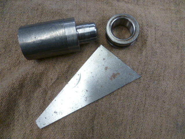
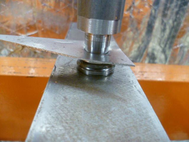
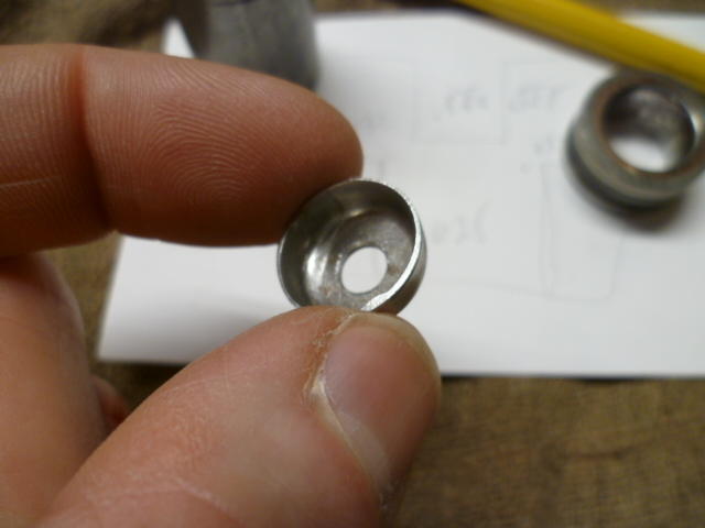
Yes! Yes!! That's the one! Thanks! I was pretty sure it was you or convertt, but finer details continue to slip. They say it won't get any better... So I guess now that you've already answered the process question, that half an hour I spent in the shop this morning doesn't add much more to the discussion. But for the record... For the female portion, I used an old bearing race because its what I had laying here, and it's hardened. For the male portion, I used a previously machined drop of 12L14 steel because it was already machined to close to the size I wanted. For a real product, 12L14 is definitely NOT what you would want to use as pretty much it's only claim to fame is it's ease of machinability. Doesn't heat treat, doesn't weld well, isn't particularly strong, but boy it sure does machine nice. Anyway, hardened race with .625 inch ID. 12L14 male mandrel with .555 inch diameter, and .032 thick steel sheet. It took two tries to get the mandrel diameter correct, and I suspect this is where all the skill and experience comes in. You need the correct clearance between the mandrel and the die for the thickness material you're working with. Not enough clearance and it acts like a hole punch. That's what my first try did. So I took ten thousandths off the mandrel and things got a lot better. And by the way, this forming process is known as "drawing". I assume there's oodles of info on the web if you want to research. On the hydraulic press. My 2 ton arbor press wasn't enough and I didn't want to rip a shoulder out of the socket: Here's the result. Note the tear through on the first attempt and the better draw on the second (lower) form: Trim the excess material off and put a hole in the middle just for show:

-
And then call 911.
-
Haha! Ok, I think I have enough "stuff" laying around the shop that I can at least mock something up quickly and show you what I'm thinking of. And as for the heat treating, it's not quite like that. First - Make sure you know what type of steel you're working with. Not all steels have a composition that will react favorably to a heat treatment process, and even the ones that do, will have a different process depending on the composition. For example, above, you referenced an oil quench... Well that works great for "oil hardening steels", but not so good for "air hardening" or "water hardening". The three most common ubiquitous categories available everywhere are Oil, Water, and Air hardening varieties. I've got a bunch of "O1" (Oil hardening) laying around here and that's what I would use, but it's probably not the best choice for a die like that either. Would be OK, but not great. However, you've got no idea what you've got laying around, so I would just skip the heat treat process completely unless you're sure what you're working with or just want to experiment and see what happens. Second - The temperature you described above is not high enough. Needs to be full cherry red. One simple way to determine if you're hot enough is to use a magnet. The steel will actually lose it's magnetic characteristic when it's hot enough. It will be glowing red and it won't be magnetic. Then quench (using the appropriate method). Third - If the heat treat was successful, the part will be hard. Like real hard. Glass hard. File skates across the surface hard. Problem now is that the part is TOO hard. Too brittle. So you need to "temper" the part to draw back the hardness some. For that you re-heat the part but not as hot. "Straw color" is a term thrown around a lot. Heat the part "to straw color" and then let it cool slowly. After that, the part won't be hard brittle anymore and won't shatter like glass when you put in the press to make your washers. And don't forget that all the while, the glowing part has been oxidizing on the surface and by the time you grind the scale off, what's left is now the wrong size....... So you add to your long bucket list of projects, an argon purged heat treat furnace......... I would skip the heat treat and just make a new set of dies when the first one wears out.
-
Making a set of dies to produce a suitable replacement for that cup washer should be an easy task on the lathe. Without heat treat, I don't know how many shots you would get out of it, but certainly enough to get you through the task at hand. But wait a minute..... Don't you have a lathe? Brain isn't able to pull the details from the corners right now, but someone here on the forum did some cold metal forming recently. Made some dimples in something or made some sort of formed washer? Don't remember who and I couldn't turn it up with a quick search. @ConVerTT , @grannyknot ?
-
Agreed! Me too! And as 240260280 pointed out, it's clearly Klingon. I believe it's three bat'leths bolted together.
-
I hoooovered this from the interwebs. Probably from somewhere here on the forum:
-
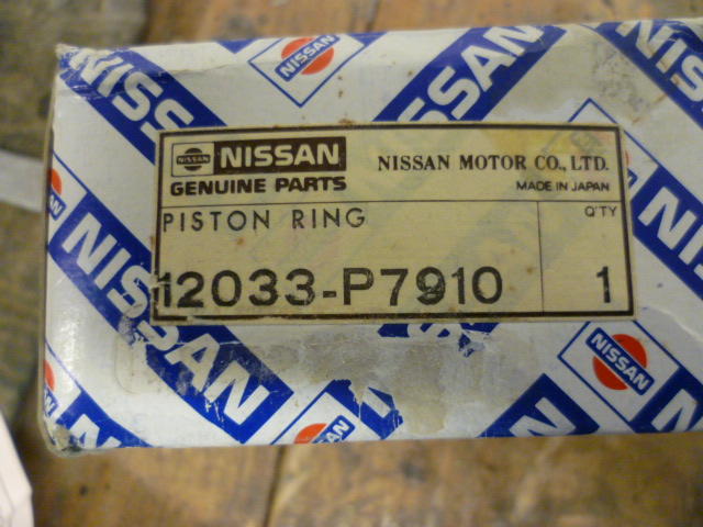
Here's the rings I used: Checking ring gaps: My ring gaps (like @Av8ferg) came out within spec so I did not need to do any gap grinding. Top ring gap - Spec is .009 - .015 and I get .014 on mine. (Note that I measured .020 to .024 with old worn top rings) Middle ring gap - Spec is .006 - .011 and I get .009 with mine. (Note that I measured .014 to .015 with old worn middle rings) Oil scraper rings - Spec is .012 - .035 and I get .014 with mine. I did not measure old oil rings.

-
I'm using stock iron Nissan rings and "I read on the internet" that 240 grit is a good choice for standard OEM iron rings. For example, here's a snippet from the ball hone company's website. From https://www.enginehones.com/technical.html ~~~~~~~~~~~~~~~~~~~~~~~~~~~~~~~~~~~~~~~~~~~~~~ What GRIT should I order? Hone grit is one of those topics that will vary vastly from OEM manufacturer, ring designer to professional engine builder and will depend on how bad the cylinder wear is and whether a deglaze will do the job . If you have a poor condition bore with rust or deep grooves you will need to use a 120 grit hone to remove the rust and remove the deep grooves. Then follow up with the appropriate grit depending on ring application. For a basic deglaze to refresh the engine just use the grit depending on ring type. EngineHones.com has built several engine mules (our guys race too!) to investigate the grit question with on-track results. The table below which was derived from our engines, ring manufactures and technical literature. Our best seller to commercial engine rebuilders and power-sports shops is the 240 grit hone. Our guidelines are as follows: Iron Cylinder Ring Type: OEM Iron rings: 180 or 240 grit Chrome rings: 240 or 320 grit Moly Rings: 320 or 400 grit Plasma Rings: 320 or 400 grit not sure ring type: 240 grit ~~~~~~~~~~~~~~~~~~~~~~~~~~~~~~~~~~~~~~~~~~~~~~~ And there are a bunch of other enthusiasts sites on-line that echoed the same recommendation, so that's what I went with. Granted, I did not call Nissan and ask, so I could have made a grave mistake, but I hope not. I'm no engine building expert and I would be interested in hearing from anyone who has expertise in such areas and would like to throw themselves in front of my build train though. I don't have pistons in yet.
-
Yup. One of the things they say is to always insert and remove the hone while it's spinning. That's why I was "bumping" the drill while I put the hone into the cylinder. Taking it out is easier (and smoother). And yes, you are shooting for a 45 degree angle, but it's not 45 WRT horizontal or vertical. You're actually looking for 45 degrees between the crosshatches. So each opposite direction crosshatch would be 22.5 degrees from horizontal so that when added together, they form a 45 degree angle between them. Does that make sense?
-
I (think I) managed to get a video uploaded... https://www.youtube.com/watch?v=WaEgaQ92rj4&feature=youtu.be
-
That's pretty much it, but I had one other advantage in that I had a trashed "nobody cares what happens to it" spare block here to practice on. So I had six cylinders to get the rhythm down on before I moved to the two other blocks that I DO care about. Hopefully by the time I moved to the two good blocks, things were consistent and my angles turned out right. And having my coxswain there helped. I just like saying that.
-
And BTW, I'm not looking to remove any defects with this honing. I'm just looking for new oil holding scratches to seat my new rings. So I may not have gotten 100% coverage on every square millimeter of cylinder wall, but I don't think I really needed that. I guess I'll find out in a couple thousand miles!
-
Of course, the stroke speed is related to the drill speed and with MY drill running about half-full, it turned out to be about one stroke per second.
-
@Dave WM, I was looking through some files and turned up my schematic for the output stage: I know it's a tiny portion of the whole but that's all I got.

-
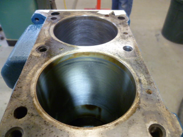
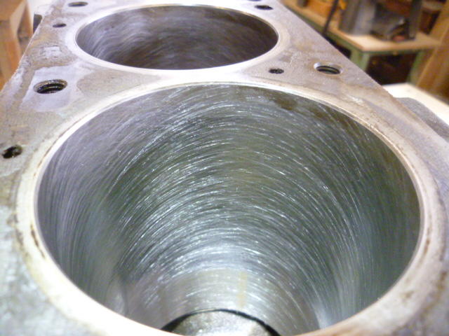
Now that the main caps are off and the crank is out, I honed the cylinders. Bought a three and-a-half inch 240 grit silicon carbide ball hone dingleberry: I ran the drill while my build buddy @GGRIII manned the WD-40 spray and kept me in-time on my stroke frequency. I think that makes him my coxswain (snicker). In this pic, there's an un-honed cylinder in the foreground and one that I honed in the background. I was attempting to get the hone marks of both cylinders in the same shot so I could compare them, but after all the miles the stock honing is hard to see: Here's a closeup of what I did. About 20 seconds of honing per cylinder and I ended up with this: I've got a two second video clip example that I will upload as soon as I figure out (again) how to run youtube.

-
Has anyone tried just roughing up the metal toggle handle and painting it flat white? And if someone really really needs a plastic one and has a dead example for autopsy, I bet I could come up with a plastic replacement. Might take 100 hours and cost thousands, but I'd be willing to at least take a look at it.
-
-
Have I mentioned that one of the transmissions I've been into, I was into so many times that I could do a whole disassembly and reassembly blindfolded. I did it once just to prove I could. Simple three speed box, and I was into it way more times than I should have been. And it was all my fault.
-
Yeah, even if the jaws DO meet together flat and close down completely, the three jaw just isn't the most accurate tool in the drawer. Works fine if you're starting with a piece of stock larger than you need and turn all of the important features without taking the part out of the chuck. That way, even if the chuck isn't accurate, it'll come out in the wash because all the surfaces you turn will be concentric with eachother. Don't worry about the jaws of the 3-jaw unless they're really really bad. Just understand the limitations and use it accordingly. Use appropriately, it'll produce accurate work. So you're thinking to yourself... No prob. I can chuck that shaft up in my 4-jaw and indicate it in, right? Answer - No. Even if you indicate it to zero at one position out from the chuck, you haven't guaranteed that it's parallel to the ways. You can put something into the 4-jaw crooked and STILL make it run true in one location.
-
I was going to suggest that to you. My assumption is that the error is in the measurement method, not the shaft. And it's probably not the lathe spindle itself. The spindle is probably pretty good, I bet most of the error is coming from the chuck and the unrepeatability of the mounting of the part. If you're just tossing the shaft into your three-jaw and tightening it down, it's not going to be centered unless you've got a fantastic three-jaw AND you get lucky (that time) when you put the part in. If you really want to check something like that you'll have to do it between centers.
-
Haha!! I was thinking the exact same thing! And it probably involved lasers. And possibly even sharks. Where I come from, "HSS" is "High Speed Steel", and is hardened. I'm assuming that's not the same thing you're using it for, because if so, there's no way you're going to use it for a rotisserie.
-
Interesting! And cheap! The "used on" info on rock auto shows as: SUZUKI SWIFT 1995-2001 How did Harold figure out they fit the Datsun?

