


Captain Obvious
Community Member
-
Joined
-
Last visited
Everything posted by Captain Obvious
-
Looks like we're gonna need a bigger beer.
-
You want to see movies, or just the summary?

-
Stick, Yes... We have clearly veered into a purely academic avenue on your thread, but we're good clean fun. We'll help with the math.
-
Haha!! Just trying to pay it forward. What's the prospect of all three of us having our new shiny motors powering our cars at ZCON 2020?
-
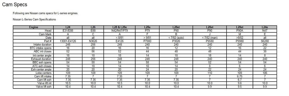
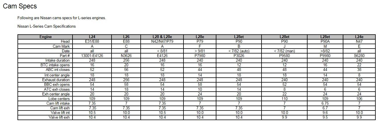
So @GGRIII and I are putting motor parts together and he's got two cams... One of them is an "F" grind from an 82 non-turbo car and the other one is a "B" grind from an 82 turbo car. We're trying to figure out which one would be better to use. According to the interwebs, the lift numbers for both of them are the same and the valve timing specs for the two are as follows: Format in FSM - a / b / c / d / e / f - ex duration / intake duration / intake open btc / intake close abc / ex close atc / ex open bbc "F" (na) - 248 / 240 / 16 / 44 / 10 / 58 "B" (turbo) - 248 / 240 / 12 / 48 / 14 / 54 It appears to me that the only difference between the two is the non-turbo (F) has all the valve timings four degrees advanced when compared to the turbo version? Seems to me that the turbo cam on sprocket position #2 would be identical to the non-turbo cam? Do the cam experts here concur?
-
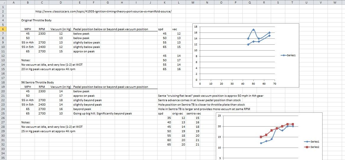
Of course they did. They always do. To add some info to Zed Head's post... The ported vacuum signal only provides vacuum at a "light cruise" pedal position. There's no vacuum at idle, and the vacuum falls off quickly above light cruise. It's peaky right at one throttle blade position (light cruise), not simply when the throttle is open. And there are two ported vacuum connections off the bottom of the throttle body. Make sure you are using the correct one. You want the one on the right side. The other one is for the EGR system.
-
Lol. I could do that. But it would be waaaaaay down on my priority list! Those metal can circular integrated circuits were used starting in 75. The pins were identified with letters "A", "B", "C", etc instead of pin numbers 1, 2 , 3. Precursors to the plastic DIP. This one is from 77:
-
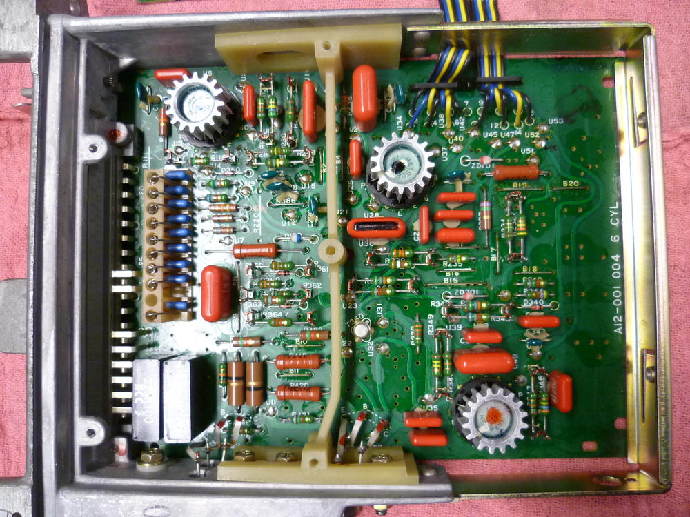
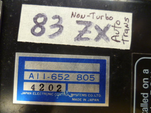
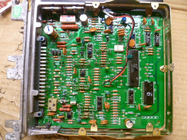
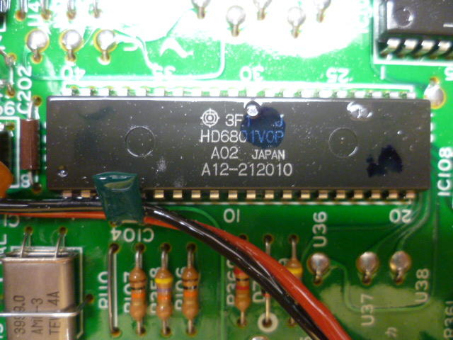
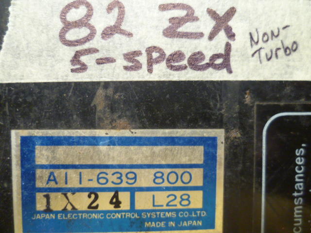
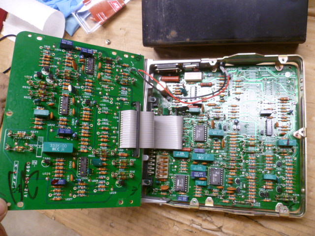
So we're clearing into the academic portion of the thread, but I got some pics... Here's the ECU that I took out of an 83 NA with an auto trans: Here's a pic of the inside: And here's a close-up of the microcontroller. Hitachi HD6801VOP. Also note that you can see the 4MHz crystal in the lower left corner of the pic. Now granted... Just because there's a 4MHz oscillator doesn't guarantee that the microcontroller is actually running at 4MHz. I don't know if they are dividing that down or PLL looping it up. But my assumption is that the microcontroller is running at 4MHz : And since I had the camera out... Here's the ECU out of an 82 NA with a 5-speed trans: And the internals are still analog voodoo: So my (one and only) data point seems to indicate that they went to computer control in 1983.
-
It's my understanding that if the hydraulic lifters are failing, they will fail "short", not too long. By that, I mean... The failure mode is they leak down and then fail to pump up to the proper length. Valve clearances will be too small. And if the valves never open (or only open a tiny bit) because the lifters are too short, If that's severe enough, I'm assuming that could cause low compression.
-
LOL. Me too. Changed my life. Interesting though about the numbers... The 6801 is a microcontroller with on-board RAM and ROM while the 6802 is just a processor. So even though the 6802 has a higher number, it doesn't necessarily mean it's "more".
-
The ECU I have here is from a non-turbo 83 with an auto trans. I believe it's the original ECU from the car. I'll get the number off the case when I get a chance. And take a pic of the microcontroller.
-
Well this EFI guy can tell you that by 1983, the ECU's WERE computer controlled. 6801 microcontroller running at 4MHz I don't know when the transition officially occurred, but by 83, they were programmed devices.
-
I get that. My suggestion was that you could use COP's and connect them in parallel pairs and do the same thing on the low voltage side instead of sharing a high voltage coil between two plugs. You would still be wasting a spark, but it's not the traditional "two plugs in series" circuit. Gives you the same distributor-less function as the traditional wasted spark system, but you wouldn't get any weird electrode erosion and the energy used to fire the plug on it's exhaust stroke would not be subtracted from the plug that really matters. Instead of "two plug in series being fed from the same coil", you could use "two coils-on-plugs in parallel being fed from the same control source". Maybe it would be clearer if I whipped up a couple simple sketches?
-
Since two plugs are always fired in pairs, I don't think so. Out of curiosity,,, Why would you need different dwell on just cylinder #4 (for example) than all the others? So I haven't thoroughly researched the name "Wasted Spark", but I always thought that the "waste" was referring to the spark on the exhaust stroke that didn't do anything. Didn't cause any harm, but it was "wasted". If that's the true origin of the name, then what you said about the spark jumping backwards doesn't have to be the case. Granted, most of the times the wasted spark systems pair two plugs in series on the high voltage side, but I don't see any reason why you couldn't simply connect two COPs in parallel and fire them at the same time from the same low voltage source. You wouldn't have the (cost) benefit of cutting the number of coils in half, but you could still run COP with a wasted spark system. Some people may consider the removal of the high voltage wires a benefit worth the extra cost of three more coils.
-
Haha!! Glad to help. I only even know that because I modified the shocks from my old 260 to allow the new owner @GGRIII to customize the bumper depth.
-
I've been casually rolling some ignition stuff around in recently as well. Stuff like who controls the dwell and advance, etc... Different options and the like about that. Here's a bunch of links I was poking around on: https://www.hotrod.com/articles/convert-a-ford-or-chrysler-ignition-to-gm-hei/ https://www.powerperformancenews.com/tech/spark-it-up-how-to-convert-a-ford-or-mopar-distributor-to-gm-hei/ http://megasquirt.free.fr/sources/MS/manual/ms2/GM_7pinHEI.htm http://www.megamanual.com/ms2/GM_7pinHEI.htm http://www.megasquirt.info/HEIgn.htm https://www.hemmings.com/magazine/mus/2008/11/The-lost-art-of-servicing-GM-HEI/1719426.html https://www.celica-gts.com/forums/index.php?PHPSESSID=m15m00cdf1sj27pk5r472sjv05&topic=11116.15
-
To clarify-- Nuh-uh. The bumper shocks started in EARLY 74. My thin bumpered early 260 had the shocks.
-
I'm not sure what that fourth connection was intended to do. The first year for the carbon canister was 1974, and (even though the 1974 model used carburetors) they capped off that fourth connection. I don't think "CARB" means "Carburetor". I would guess that it means "CARBON". I've never seen a picture or vacuum diagram that did NOT have that fourth connection capped off. I don't know what it does.
-
It screws into the block, or the head? You got a pic?
-
The thing about the cam sensor... If you're running a wasted spark system, you don't need cam sensor. Two pistons will be approaching TDC at the same time. Of the pair, one of the rising pistons is approaching TDC on it's compression stroke, and the other one is approaching TDC on it's exhaust stroke. A cam sensor would allow you to differentiate between those two, but if you're running a wasted spark system, you don't care... Just spark both of them at the same time. If you had a cam sensor, you could spark just the cylinder on it's compression stroke alone without "wasting" a spark on the other cylinder. On edit - I don't know about the accuracy of the spark timing stuff. Maybe a cam sensor can get you a tiny bit more accurate with your spark timing, but I'm not sure.
-
Huh? Who said that? Seriously though, I hope this whole thing was a non-problem and will resolve with no internal surgery required.
-
@Mike, LOL!
-
Haha! Well I had very little doubt, but someone had to ask!
-
Have you checked the oil level? I'm Captain Obvious, and I approve this message.
-


Important Information
By using this site, you agree to our Privacy Policy and Guidelines. We have placed cookies on your device to help make this website better. You can adjust your cookie settings, otherwise we'll assume you're okay to continue.