


Captain Obvious
Free Member
-
Joined
-
Last visited
Everything posted by Captain Obvious
-
 Back story? Typical. I bought it a number of years ago with very little detailed info about it's history. I got a couple pictures from the PO taken during some of the work he did to the car, and a couple of the pics show the head off the engine, so I know he did that much. I also have a stack of receipts that include ONE piston and rings for said piston. So I don't know what goes wrong with an engine that requires the replacement of just one piston, but the implication is..... My PO has been into the bottom end as well. Kinda makes me wonder what kind of trouble lurks down there. All that said... I didn't buy the car for the condition of the engine. I bought it for the condition of the underside. It's pretty much rust free. To me, everything else is easy.
 -
Thanks all for the encouraging words, and thanks also for the additional investigative work on the head thickness. I guess the bottom line is that I've got a reasonably high degree of confidence that my head was never planed. Surprising to me that the PO would get as deep into the head and NOT have it cut, but thankful for small miracles. Just one less thing to get screwed up under his ownership. Right. I saw that in the manual. The point of the pic is that so far I've taken out one of each direction so far. My PO apparently didn't know they were unidirectional and just tossed tehm in random. I will put them all in the right way when I put this thing back together.
-
I love the look. My guess is the only reason they made the headlight scoops a separate piece is they just couldn't form one sheet into the shape they wanted. Either geometrically impossible, or too much stretching for the metal to handle. I suspect if they could have successfully made the fender / scoop one piece, they would have.
-
-
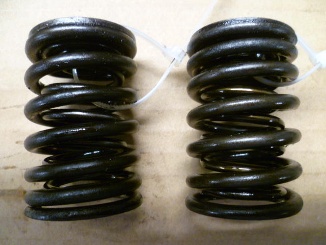
So I started stripping the valves out of the head. Next chance I get, I'll post up some pics of my home-brewed valve tool, but in the meantime..... So I'm taking the valves out, and here's the springs from a couple of the valves. I never even knew the springs had a variable pitch and a "proper direction" to them, and apparently neither did my PO. The retainer caps are at the top for both of these, but the pitch direction is different between the two: I'm not sure how much difference it makes in the grand scheme of things, but just another detail that was missed.
-
Even though functionally it's not critical, It would be highly un-Japanese to not control that dimension from the factory. These things are running down the assembly line and IMHO it would be extremely unlikely that they were not all peas in a pod to within a thousandth or so.
-
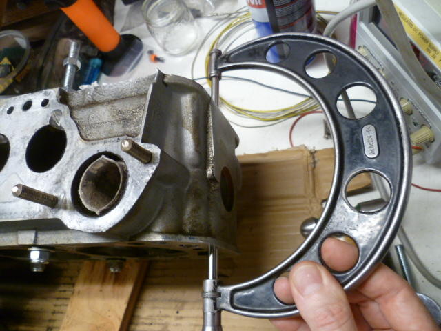
Well I don't have an explanation for why your E88 is different than my N47, but I do stand by my numbers. I cleaned off the measuring surfaces and even broke out the big guns. More accurate than the springy calipers for things like this. I don't know the last time this ol' girl saw the light of day, but she's still got it where it counts: Installed the correct anvil, checked her against the measurement standard rod, and then rechecked the head. I get the same thing I got before. About 4.254 inches or about 108 mm. So I don't know if they changed the head thickness over the years, or if yours has been cut.

-
-
-
Well, duh.
-
I call BS on the original paint. For that call, I cite (in addition to the blue on the door jamb plate) overspray on the wiper stalks, hood latch, and brake booster check valve. In addition, it appears there is blue paint on TOP of the dirt on the hood hinges. I got no dog in this fight, but I call BS.
-
I will get a better measurement on the head thickness once I get things cleaned up. But even though I took just a quick check, I don't think I've got eight thousandths of grime on my head. There might be a little error in my 4.255 measurement, but just a couple thousandths. Plus or minus two thousandths maybe? Probably not eight. So either they made the N47 head thicker than the E88, or I'm thinking your E88 has been cut. Anyway, when I get things cleaned up a little more, I'll take a more reliable reading.
-
So with the incredibly generous help from @jonathanrussell, I've got a replacement cam on the way. Since they are both factory grinds, I'm hoping his cam is a drop-in.... errr.... slide-in replacement for what I have now. So with his help, I'm not out of the woods, but I should be a lot closer to the tree-line than I was before. This people here on this forum are fantastic!
-
I'm not sure if my PO had my head planed as part of the "work" he did to the engine. I took a quick look through the FSM and I didn't find a spec for the overall thickness of the head when new. Is that number known? I measured my head thickness at 4.255 in (108 mm)*. Anyone know if that's factory original thickness, or if it's had material removed? * I didn't clean the head well before that measurement, so I could be off a couple thousandths.
-
Wowsers!! Yes, that's exactly what I have now. Both pieces. Haha!! I measured my lobes at 1.585, so the same as what you have there. I'd love to have it! Thank you so much for the offer!! PM on it's way!
-
Yeah, it's unfortunate that I'll miss this one. Was really looking forward to the group meeting of the Flat Top Advanced Research and Development Society. So if I'm not there... Can I count on someone else to do something stupid in my absence? Is @siteunseen gonna be there? He'd have my back on that.
-
It's probably the ink from the warning label that's the problem.
-
-
So, as a follow up to the above, I pulled all the cam towers off and found all sorts of other issues as well. Less severe than the above, but I also found: Screwdriver pry marks (and corresponding burrs kicked up) at the seam between the towers and the head because he had a hard time getting the towers off. Small flakes of aluminum smashed between the towers and the head. Presumably little pieces of material scraped off with the screwdriver used above. Small chunks of carbon junk smashed between the towers and the head. Burrs kicked up on the alignment rings from using pliers to pull them out of place. And one of them was ovalized a little bit from too much force with the pliers. So just as a quick test to see if it was possible... I carefully dressed all the mating surfaces to remove the burrs on the head, the towers, and the (salvageable) alignment rings and put everything back together. I got it to the point where the towers properly sit flush against the head and I can align them so that the two parts of the cam spin easily with two fingers. I haven't tried it with a complete cam, but it looks like this head may actually be salvageable. So... Long story short. my PO's workmanship strikes again. Not enough cleanliness, attention to detail, and understanding of what's important. Please step away from the motor, sir. Just walk away. Anybody got a Nissan "A" grind cam laying around they would part with? I think that would be my fastest route to getting back on the road for the rest of this summer.
-
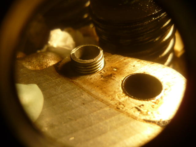
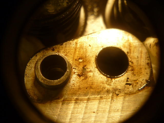
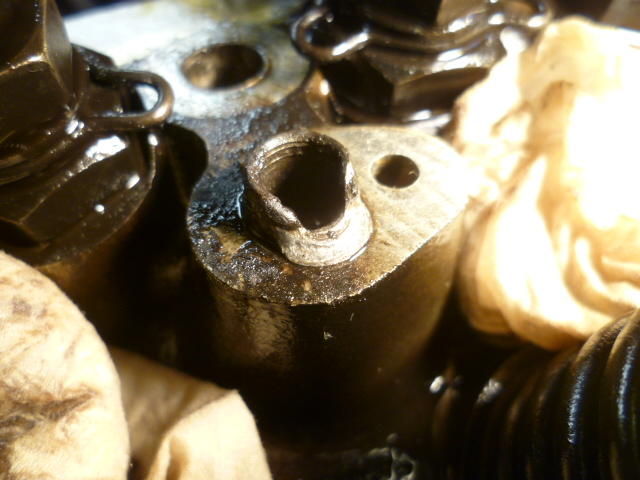
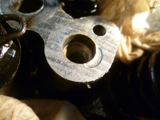
SMOKING GUN!!! So I was messing with trying to align the cam towers by loosening them a little bit and trying to get the cam to spin smooth, but #3 kept giving me trouble. Just didn't feel right. So I decided to pull it off completely and see what I could see. And....... Here's what my Previous Owner put in there on one side to "align" the tower to the head: And it gets worse... Notice that since that threaded "thing" is so crappy, it caused the other side alignment ring to be so far off that he had to use the cam tower bolts to jack the tower down (because it was out of alignment). it caught the alignment ring on the other side and pinched it in the gap and smashed it. Here's what used to be the precision alignment ring: The ring got smashed and actually extruded a tongue of material out into the seam between the tower and the head. Pulling that damaged ring out, you can see the dent it left in the aluminum head: At first, I thought that threaded thing was a Helicoil or something, but it was just a short stub of bolt that he drilled out. I guess he lost or mangled the original alignment ring and made that instead. Here's the two pieces that were "aligning" my #3 tower: Previous Owner strikes again!!! It's beyond me how you can't tell that something doesn't feel right as you need a wrench to crank that tower down into place and crushing that alignment ring in the process. I know the hobby is filled with people of varying skill levels, but this surprises even me.

-
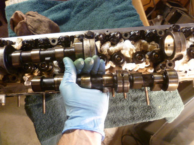
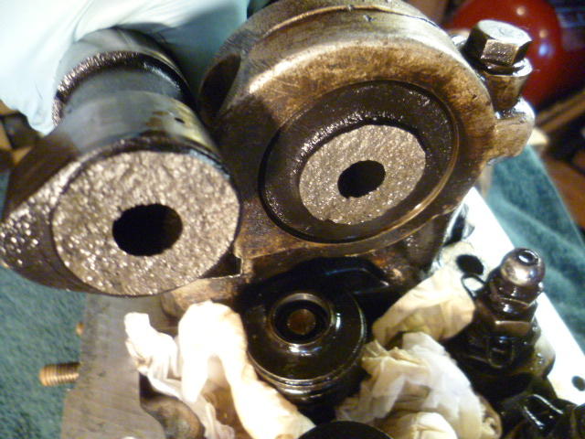
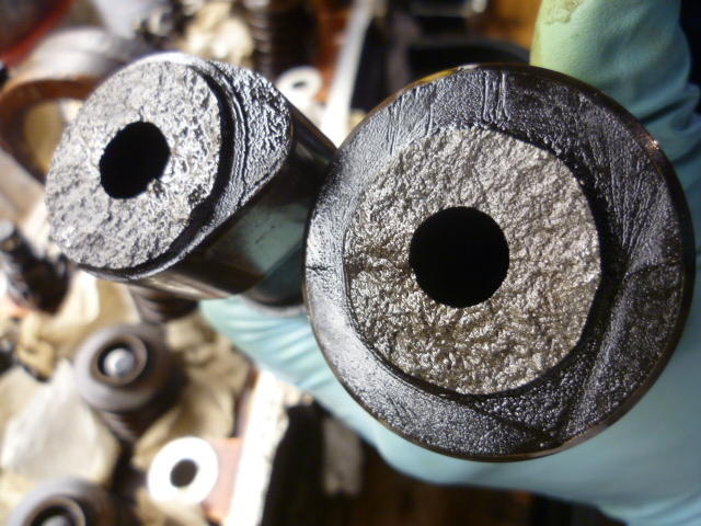
Head is off, and by some incredible stroke of luck.... No contact between pistons and valves!! So I don't know if the engine isn't interference (with the dished pistons), or if I just got lucky and the rear half of the camshaft just happened to stop in a position where none of the valves were open enough to cause a problem, but whatever the reason, I'm thankful for small victories. Here's a pic of the valves from one of the rear cylinders. They all look like this. No clean spots and no hint of collision: My beautiful camshaft. The rear portion spun really easily in the two rear journals. I just slipped it out the rear of the head: The front portion of the camshaft spins relatively easily, but not as easy as the rear half. There is also one part of the front half rotation where it gets a little tighter. Not so tight that I can't turn it by hand, but to my calibrated hands, it's a little tighter in one spot then the rest. I wouldn't be surprised if there's some sort of alignment issue with the cam journals that was stressing the shaft for the past five years. Here's the break area. I don't have any of the typical beach marks of a gradual failure. It looks like it was a one time catastrophic snap: I took the front half out to get a better pic. Here's another close-up: Next chance I get, I'm going to put the front portion of the cam back in and see if I can loosen up the front towers and get them aligned better. I suspect that if I loosen them up and tighten them down again evenly I might be able to get rid of the rotational tight spot. Just to see if I can.
-
What he said! So how's it running? Cold, hot? Everything stable?
-
Thanks for the compassion. The general consensus is that the design IS an interference engine. So if that's true, depending on where the cam stopped, there may be some significant carnage. I should know for sure very soon. I don't have a borescope, but I did pull the plugs and have a peek in the holes. I see some stuff in there that doesn't look right. Can't tell if it's evidence of a collision or what, but something in there is weird.
-
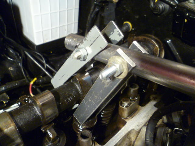
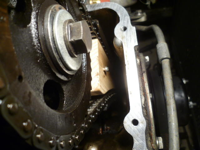
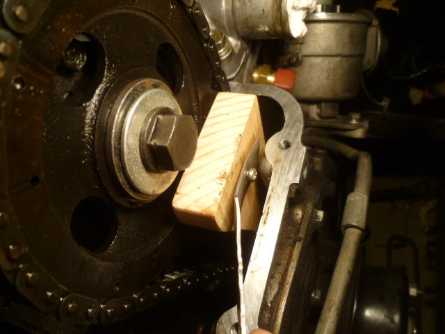
Update on my dead engine project... I made a rocker removal tool. After multiple failures and spending waaaaaay too much time on it, I finally hit on a geometry that worked: I took the rockers out so I could turn the cam without having to worry about valve positions, etc. I put the engine on #1 TDC before taking stuff apart so I knew where everything was. Way easier to spin the engine over with the plugs out and all the rockers removed. Then I made a cam chain wedge tool. My tool is about an inch longer than average because that's just how I roll. I wanted to get the tool down as deep as possible to assure it was holding the tensioner shoe back. I also came up with a (yet to be fully tested and therefore potentially stupid) removal plan. That's the screw on the front and the metal removal handle: Since the tool is longer than most, I had to remove the cam gear bolt to get the tool into place. Being careful not to knock the gear off the end of the cam (not really a difficult task), I took out the bolt, slipped the tool into place, and then put the bolt back in until I was sure the tool was fully seated in place and holding the chain: Here's some pics of that whole process Bolt out just long enough to get the tool to clear the bolt head: Then get the bolt back in place for now: And here's the tool fully installed wedged into place: And here's how the removal tool is supposed to work: Hook the screw head with the hole in the metal handle: And pull the wedge back out: Worked in test. We'll find out later if it works as well in real practice.


-
I gotta believe there are a lot of people doing this, aren't there? I'm not going to be cheaper than them. You think I would do it better?


