Captain Obvious
Free Member
-
Joined
-
Last visited
Everything posted by Captain Obvious
-
 The video worked OK for me. Cool video. After you fix your rev counter, can you post the next video both in slo-mo and at regular speed with sound? Would be cool to seem them both and might help figure out what's going on.
 -
-
Glad you are able to focus now. Life gets in the way whether you really "let it" or not. I'm just back on the radar a couple days ago after a sports injury.
-
Somewhere I think I read that it was Time to refocus on your Zs. That was about three years ago?
-
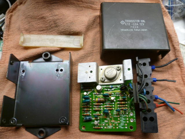
Wow. Lot of changes from that unit to 77. My 77 only has one electrolytic cap. Everything else is film.
-
I've never vulcanized rubber. Anyone here done that? Is raw un-vulcanized rubber easily available?
-
-
-
jwtaylor. Thanks for checking! munters, Sorry it didn't work!
-
Glad to help. I thought that might be part of it. So, you could always just give it a try and see if you can get it out. If not, you haven't wasted any work... You'd still have to disconnect that U-joint anyway to get the column out.
-
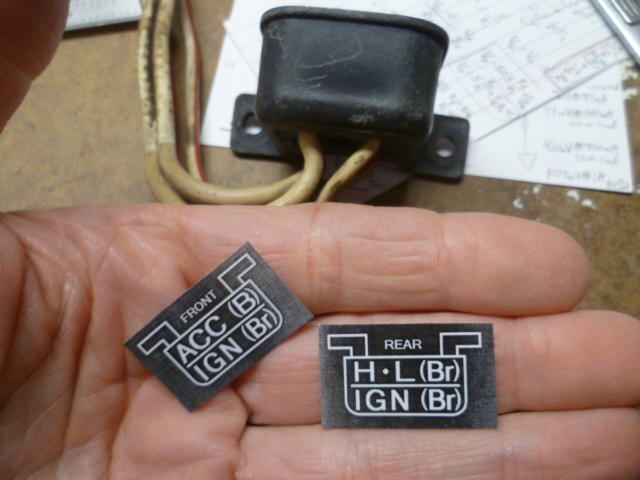
Used on the early cars only. Reminds me of a joke... "Hey! This box has crap in it!!!"
-
Wow... Good question. I don't know. I suspect that very few people even know that bottom portion comes out so easily!
-
In an effort to get some more pertinent input, let me rephrase the question... The rotating shaft that runs through the center of the steering column shaft for the 240's is made up of two portions. Let's call them upper and lower. The upper portion (where the steering wheel attaches) is held in place by a spring clip and cannot be removed without disassembling the column. However, the lower portion (the portion that sticks out of the bottom of the steering column in the engine compartment) is not held place in by any means and if it weren't for the U-joint being bolted at the bottom, the lower portion could be pulled straight out of the bottom of the steering column. Question is.... Is there room to pull that lower portion of the steering shaft out while the steering column is mounted in place, or must one go through the trouble of taking the entire steering column out of the car first? Will that lower shaft clear everything in the engine compartment (like the engine mounts, etc) or will it be impossible to get it out?
-
I'm trying to follow the pea... "This 240Z is offered by the selling dealer in Oklahoma with ... a clean Delaware title." Back when Bill R. bought the damaged car for $100 (in TX?), was it a salvage title? Did the guy he bought from have comp. coverage on it when the tree fell on it and buy it back from the insurance company?
-
Might just be me, but I get "Error: Unsupported video type or invalid file path."
-
Zactly. And now, I keep rolling right into Moby Dikk in my own head! I drove around listening to that album so much that I think it was 50% slower than new due to the inevitable 8-track tape stretch.
-
Glad to help. Thanks to you, I'm much obliged for such a pleasant stay. But now it's time for me to go.
-
Well that's not good. Do you have another rack you're going to put in, or are you thinking you'll weld that crack up and reuse that rack?
-
I'm not a ZCCA judge, but that does not sound right to me. Since that was a documented dealer modification (not quite a "recall"), I would expect that to be accepted as "normal" when being evaluated. I would hope that cars that had those mods would be considered totally equal to cars which had not. But, of course... My opinion doesn't mean squat.
-
The holes at the bottom of the 72 carbs are for hot coolant to be pumped through the carbs to warm up the nozzles. You can put 72 carbs on earlier manifolds without having to do anything else special to accommodate those holes. Just slap 'em on. Plug the holes on the carbs if you don't want wasps to build nests in there, but other than that, nothing. Putting earlier carbs on the 72 manifolds are a little more involved, but I don't think that's what you're asking, right? And in the pic with the 72 manifolds, I can see that the heating water lines aren't hooked up either, so it wouldn't really matter. Yes, I'm rambling. Did I answer your question?
-
-
-
Oh, sorry. I thought you had already torn the rack down and cleaned everything up. Yeah, you have to get all that old crusty plastic grease out of there. That could certainly be an issue. Hopefully it's that simple! Clean that old stuff out and replace with fresh. Keep us posted!!
-
I see two things potentially wrong... First is that the floor jack appears like it could be pushing inward on the rotor and helping limit the natural outward movement of the hub as the suspension tries to move upward. Might be better to rotate the floor jack ninety degrees so the little wheels on it will allow it to move easier inward and outward with respect to the center of the car. The second thing? I can't see the right side front wheel but I suspect it's hanging free? If that's the case, then your sway bar (roll bar, anti-sway bar, etc) is fighting you. Just like it's supposed to do. In operation, the sway bar tries to keep the levels of the two front wheels the same. So if you've got one hanging and the other being pushed up by a jack, you're twisting the torsion spring that is your sway bar. You might try temporarily disconnecting the sway bar. Or better yet... Just lower both front tires onto a pair of roller bottom moving dollies. That will allow them to squirm to their proper position and then tighten up the transverse link bushing bolts while the suspension is loaded.
-
Of course I can't tell without actually seeing it with my own two beady eyes, but I don't think that's a crack. It just looks like a casting flaw. See if you can catch a fingernail on it... Does it go in (like a crack), or does it actually protrude out?