


Captain Obvious
Free Member
-
Joined
-
Last visited
Everything posted by Captain Obvious
-
 I wouldn't recommend that. I've seen where people have had stuff partially submerged in that type of chemical and it can develop a significant pit/erosion line right where the submersion stops. Something abut continually converting and rusting and converting and rusting... All along one tiny line. Ends up removing a bunch of metal right at the liquid line.
 -
Wait.... "Probably"??? So my non-expert opinion for the rusty input shaft is... I think you're making more out of it than you need to. I wouldn't take anything apart. I'd buzz the input shaft clean with a wire wheel and use a shop-vac to try to keep any debris from disappearing down into the snout. And the little bit that does get down there should be on the dry side of the seal anyway and shouldn't cause much problem. I wouldn't take the tranny apart for that. You don't even know if it works properly. I'd clean it up and put it in the car. Give it a try at speed and see what happens. If the clutch disk fits smooth over the splines, you should be good. And I wouldn't worry too much about the pits on the input nub either. A sleeve bearing is pretty tolerant of that sort of thing. In fact, sometimes they put recesses in surfaces on purpose to try to hold onto lubricant (like your steering rack bushings). I'd buzz the worst of it off carefully with the wire wheel and then sand that down to bare clean metal with some 400 grit and wd-40. Just don't go hard with the wire wheel on that nub or the splines or you could cause some damage. And then use a sleeve style pilot bearing. I wouldn't want to run a needle bearing on that, but I'd be willing to give a sleeve bearing a run there. Of course, all that's just dissenting opinion. I'm cheap and I'm no expert.
-
Excellent. Glad you got that first float pin out, and I hope you have the same success with the second. So, if you modify the carbs like I did, make sure your machinist understands that the access cap holds the pin in place and prevents if from slipping out of it's mounts. In other words... Once the cap is screwed tight into place, there needs to be a tiny amount of side to side play in the pin, but not nearly enough that it can slip out of either hole in the carb body. Too short and the pin will be able to slip out of a hole and the float can come loose on one side. Too long and the pin will punch through the cap when you tighten it down. Don't do either of those. And if you have someone make a new pin, they'll need some precise diameter sized metric rod stock for the pin. Use something already ground to size unless you have a centerless grinder at your disposal. As for the needle valves, you won't really know if there's any difference until you get things put back together again. Might be fine, or you might have to adjust the float tang.
-
Yup. My pass through the firewall was based on your fantastic work preceding mine. Mine is pretty much the same concept, but different shapes. My connection to the pedal is very different though. I ditched the original ball and attached a bracket to the end of the pedal to make connection to the cable. Not easily reversible, but I started with a donor pedal that was already screwed up by a previous owner's attempt to run a cable. So for some pics of what zKars did, have a look here: https://www.classiczcars.com/forums/topic/58472-throttle-cable-upgrade-all-the-way-to-the-pedal/ And I still promise pics of mine when I get some.
-
@Zup, You might be interested in the above as well. It's another one of the non-visible mods that I have done to the anchors.
-
Haha! I was figuring the carb was open and dry enough that I wasn't worried about fuel still inside. Sure, if it's still got fuel in it, then a torch would be tricky. But I was figuring it was dry. And yes, you would have to keep the heat away from the plastic floats themselves. I was figuring you could maybe get a little heat on the short stub of the end part of the pin that protrudes out into the hole. That and maybe some on the carb body itself from the outside at the blind end of the pin. And that rusty nut remover is an induction heater and I really doubt you could get the coil down into the hole far enough to have any impact on the pin. If I were to go through this again, I would probably drill a small access hole through the carb body to the blind end of the pin and use a small rod to push the pin out from that end. Essentially complete the pin hole all the way through both sides of the carb body. Then tap the new hole for threads and run a loctited plug screw into the hole to seal it. And, I've already fixed this problem on the last set of flat tops I worked on so it would never happen again. I made new float pins that are maybe a quarter inch longer than the original ones so there is a lot more material to grip to pull them out. Then I bored out the sealing caps to include a recessed area in the middle to account for the longer pins. Here's a couple pics. Longer pin with much more to grab: And the recess in the cap to account for the additional length: For a fee, I may be persuaded to repeat that procedure.
-
Haha!! Now that I've finished with that project, I would be thrilled to send someone else into that abyss. As you can imagine, I made most of the parts myself... Some lathe work, some drill press work, some bending and massaging. And in the end, it works great and looks like it belongs. One of those "way more work than normal people would do, but turned out great" kind of things. I don't have any pics of the final product, but for attaching up in the engine compartment, I made a bracket that bolts to the intake manifold using the two holes for the AAR. I ditched the AAR when I upgraded my throttle body and those two holes were empty so I was able to repurpose them for the termination end of the cable. I used a Honda Civic throttle cable from the junkyard and shortened it to length. I'll snap some pics when I get a chance. The most complicated part for you would be the fact that the termination end at the throttle body would need one of the wrap-around cable style linkage connections instead of the stock looking ball and socket joint. That's why I was asking if the Borla had options for the linkage style.
-
Well then as long as you don't need that tab for something else (like maybe mounting your IAC or a throttle cable upgrade), then chop away. And speaking of a throttle cable conversion... I did one a little while ago and I'm ecstatic. Everything is incredibly smooth. Does that Borla throttle body come with an option for the throttle cable style linkage termination?
-
I worry what you would do with such a device.....
-
Have you tried getting the pin to move using a razor knife next to the float hinge?
-
Of course the final check should be done with the carbs installed in the engine bay, but they sit pretty much level when attached to the engine. With that in mind, for bench testing you can stand them upright level and use that as a guide. And yes, if they are filling to the top of the window, that's a problem. My first guess would be small piece of debris partially holding the needle valve open a little bit and requiring more than desired force to get it to close shut completely. Other possibilities are the usual suspects. Worn needle,. Rubber tipped needle that has taken a set or has shrunk. Damaged or soaked float. Needle valve spring that has taken a set. etc... You really need to get the float out to diagnose, but I would hate to see you ruin a float to get that pin out. Not proud to admit it, but I've done it. I think if I had more time (at the time) I could have eventually gotten it out without destroying the float, but I was pressed for time. Maybe a little heat on the pin with one of those pinpoint butane torches? I don't remember if I tried that on mine, but it might help?
-
-
Neat. Those mirror attachments look like they might be just the ticket for getting down between the two carbs. Do report back. That would be easier (albeit more expensive) than what I do. And once you have a tool like that, I'm sure you can come up with other uses!
-
Unless the endoscope has a ninety degree head on it, you might not be able to fit it between the two carbs to view the rear sight glass. Would work easy for the front, but might not work for the rear. A little mirror on the end though, could convert to a ninety degree view. Tell ya what... Come to my place and I'll show you how to see the bowl levels in situ! $3.99 at Horror Fright. This and a good flashlight:
-
Haha! Save your pennies, keep looking, and something will certainly turn up!
-
Well it's not a guarantee that the car won't start without the air cleaner. However, there are some hose connections (like the thermostatic inlet air valve and the idle compensator) that will present as vacuum leaks if they are not connected to the air cleaner (or otherwise plugged). So if you're running way rich, then having those tubes bleeding air directly into the intake manifolds would actually HELP the engine run. But if everything is tuned properly and you are not running way rich, those unmetered air sources would make steady idle impossible and would probably prevent engine starting. Viewing the float bowl levels is easy with one of those little one inch diameter mirrors (on a telescoping stalk) in one hand and a bright flashlight in the other. Once you figure out how to angle everything, you can check the bowl levels on the car in a matter of seconds. Might be able to do it with a head mounted lamp as well, but I've never tried that.
-
I think you should stick with buying a car instead of spending so much time posting about a car you don't yet have. Good luck with the hunt!
-
Pretty good video. Some mistakes on some details and some wrong names for stuff, but nothing harmful. He pulled one of the float pins out with tweezers at about twenty minutes in. That's how the float pins are "supposed" to come out. Hopefully yours will be that easy. My biggest issue is that he spent a whole lot of time dinking around with dry mechanical float measurements... Tang should be some precise distance from the bottom of the float chamber? Rulers and calipers and all that? That's not the important part. What really matters is that the fuel depth is at the correct level in the sight glass. That's why they put in a sight glass in the first place!! Put the float tang wherever it needs to be to get the wet measurement where it belongs. That dry measurement is ballpark only. Get it close dry mechanically. Finalize it wet off the car by pouring gas into the carb. And then confirm final setting in place on the car. He says he was never able to get a view of the bowl level with the carbs on the car? Well, you better be able to figure out a way to do that because at the end of the day, that's the only measurement that matters. All the rest of that dinking around to get things spot on dry is preliminary setting only. Another issue with the whole video is it seemed staged and based on false premise. At the beginning, he's trying unsuccessfully trying to start the car with the air cleaner off. Well no shite.... The car won't start with the air cleaner off. That's probably because he's created some massive vacuum leaks with the air cleaner off. And then at the end, it still won't start because there's a wire off the ignition? Well who's to say that wire wasn't off at the beginning as well? The false premise... My car won't start. I "rebuild" my carbs (without even replacing the float needle valve or bowl gasket or disassembling the power valve to put in new diaphragms). Now my car starts and everything is all better. As proof, here's some shots of me happily tooling around my neighborhood. Don't get me wrong, I'm not really knocking it. I'm happy to see someone actually working on the flat tops and giving them some love. That video could have just as easily been "here's how you take them off and replace them with round tops". Haha!!
-
It's a little complicated... Kinda depends on semantics. Your recollection that the flat tops are more desirable is completely wrong. The round tops are much more "desirable" than the flat tops. As proof of that, there are clearly waaaaay more people who desire round tops than flat tops. And all of the above is completely true: In 73 they changed to the flat tops. They have garnered a poor reputation. They have been nicknamed "boat anchors". It is not unusual to see round tops where flat tops originally resided. They are more complex and harder to find parts for than the round tops. And it is difficult to find knowledgeable help with the flat tops. Probably the most important parts are the final two points, but the flip side is... You can make them work great if you can find parts and have knowledgeable help. So the summary is that while the round tops are currently way more "desirable" than the flat tops, there is a small but growing contingent of 73 and 74 Z owners who are bucking the trend and are using flat tops on their cars. With great success I might add. Personally, I was into triple digits at least three times last weekend in Z's powered by flat tops. Those flat tops started great cold, idled fine at all temps, pushed you back into the seat at WOT, and got great gas mileage when your right foot wasn't deep into it.
-
Actually, you have the better set of flat tops there. I wasn't there at the time, but from what I've heard, the earlier versions with the square float chamber covers were a problem and a lot of them were updated by Nissan to the newer version like you already have. However, yes... One of the things that was easier on the earlier versions was getting the float pin out so you can pull the float and remove the needle valve. There isn't a lot of material to grip down in that hole, and my advice is to use carb cleaner and lube on the pin until you can finally pull it out. Narrow tipped pliers is the way to go. Don't mangle the tip of the pin to the point where you can't grab it anymore or you'll have to resort to more dramatic procedures to get it out. Sometimes you can use a razor knife right beside the float hinge to wiggle the pin back and forth a tiny tiny bit, or walk it out a tiny bit at a time. Once they loosen up, they usually come out pretty easy. But if they are varnished in place, they can really be a bear to get started.
-
And @kats, I don't know if this is the correct setup or not, but I thought of you when I saw this:
-
 LOL! Photobomb!
 -
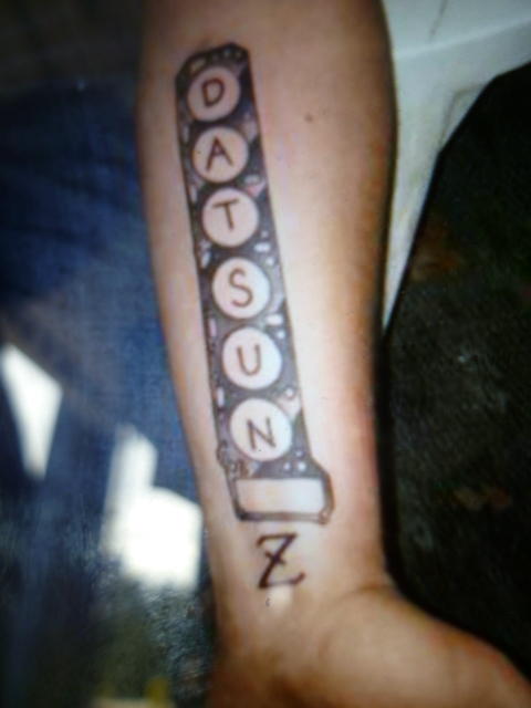
I'm home safe. Not caught up yet, but I'm home safe! Special thanks to @GGRIII my traveling partner, and @wal280z my roomie and comic relief while I was there. Thanks guys for having me covered! So the trip down, we had a couple noteworthy events. First, we learned that there is an intermittent connection somewhere in the oil pressure gauge circuit that makes the gauge drop off to zero randomly. Probably the sender unit itself is going bad. Then there was the rain in Asheville where we had to use the wipers that we really didn't want to use. But the most significant event on the way down was the chunk of metal in the tire resulting in a mandatory stop to have a tire patched. We were about twenty miles out from the show and were making our last gas stop when we saw that one of the rear tires was going down. After a couple frantic phone calls and several failed attempts to get input from locals, we found a tire place that pulled the tire and patched us up. The guys at the tire shop were enamored the car, and as it turns out one of the guys working there has a relative (nephew I think?) that is really into Datsun Z's. How much? Well... Picture of a picture, but this much: And for future reference, this is what we pulled out of the tire: The return trip home was more uneventful than the trip down. Other than having no heat (because having a connected heater core is low priority when going to Atlanta, right?), there were really no significant noteworthy events. We stayed in Harrisonburg, VA near JMU and hit a couple local brewpubs in town. But we're back, and I've got a couple more interesting pics that I'll post when I get the chance. It was great seeing old friends, even if they couldn't stay the duration, and meeting new friends! Great to put faces with names! Power to the flat tops!

-
And I heard from Cliff. He and Mark headed straight to the track from the airport. Looking forward to seeing everyone!!!
-
There are at least three sets of flat tops at the show. It's a movement!!!


