Captain Obvious
Free Member
-
Joined
-
Last visited
Everything posted by Captain Obvious
-
 Well smoking gun at least. The combo of sinking the exhaust seats, the extra deep retainers, and longer than stock exhaust valve stems. A little disconcerting that the two adjacent exhaust valves are that different in adjustment. Makes me wonder how much variability there is between how deep he sank the seats. I'm no engine expert, but I'm not totally comfortable with modifying the rockers. You would be removing material right at a stress point and introducing a stress riser right there. How much material do you think you'll have to carve out? You could stuff some rope into the cylinders and swap out the retainers for something shorter, like stock. That would take care of it, and still not require pulling the head off. More work, but no stress risers that way.
 -
Hmmm... Really not much to go on. Those old parts can be really difficult to identify. Dave, I can see why you potentially ID'ed it as an avalanche diode. Everything I found (quick internet search) in the old SOD case was avalanche style, designed for circuit protection. So how are they connected in circuit? Are the two of them connected together at the middle? If so, it's a check in the column for circuit protection. PS - I give that pic the "crappy tiny picture award" for the year. The year isn't over yet, but you're running strong to win the award!! Congrats.
-
Is the issue solvable with a lash pad change? What I mean is... The lash is too tight. Even with the adjuster all the way down. That clearly means a thinner lash pad is required. But the wipe pattern is almost off the end of the hardened pad. What happens to the wipe pattern when the lash pad thickness is reduced? I've never messed with it in any great detail. Does a thinner pad move the contact patch towards the adjuster end of the rocker, or towards the valve tip end? If a thinner lash pad moves the contact patch towards the valve tip, then this issue cannot be solved with a lash pad change.
-
When I run my adjusters all the way down, I have LOTS of clearance. Like almost enough to actually pull the rocker out without even compressing the valve spring. Almost, but not quite. Point is... Something really doesn't seem right. I bet I could install the thickest lash pad ever created and STILL have clearance when my adjuster is run all the way down. Are you double dog sure that everything else is as expected? Valve stem lengths are correct? Valve seat depth is as expected? Head not cut on the top side to clean it up? Something? And about the carb float valves... I think they switched to the rubber tipped valves in 1972 "improving sealing performance".
-
Well, at least it should be a simple fix. And I did like emccallum did... After a the initial 15 second fire-ups, when I did add liquid, I added straight distilled water. No antifreeze. Ran it like that for a little while to check for leaks. Rad cap off. Then, next step was rad cap on and let it build pressure. Then once I was convinced it would hold pressure, I drained all that out and started fresh with 50/50 distilled/anti-freeze.
-
Hahaha!!! Those are great stories!! My recent new motor fire-up was completely uneventful. I feel totally boring. No, wait... I do have something!!! It was about day three after the fire-up, and I was picking up a noise. Something weird, but certainly unpleasant in the top end. But I don't want to clutter up someone else's thread with tales of my stupidity.
-
Cool!!! I'm not sure I would add coolant until I was sure the engine ran. You can run it dry for a short time (fifteen seconds) just to make sure things work. At this stage, I would also consider the carb oil to be optional. But since it's so easy to put in and take out, it's no big deal. I would add "double and triple check that the cam timing is correct". before I spun the starter. And when you do turn the starter to prime the engine oil... I would make sure oil comes out of all of your spray bar holes. And if you're energetic, I'd run a compression test after the oil was primed and before I put the plugs in. Just to rule out surprises. After all the detail leading to this point, not much risk of any issue, but fingers crossed here just because it's a big day!!
-
Me too. The coil tab to the side made sense to me as well. But orienting both the connections in the same position didn't work well. In any event, it's really not a big deal. Thanks for bringing up the questions so I could tag along for the ride!
-
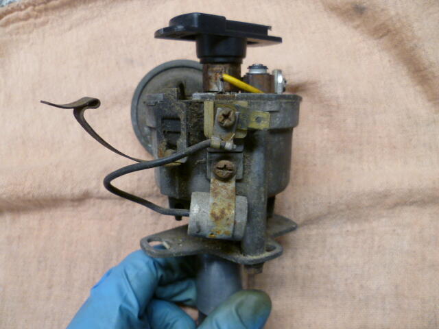
Hmmm... So on my and BoldUlysses distributors, the electrical connection to the coil sticks out sideways instead of upwards towards the cap. I had tried before to swing the condenser connection to the side (instead of from the bottom), but I changed my mind because of the poor fitment. It got in the way of the other spade to the coil. So the spade to the coil should point upwards instead of sideways? As shown on the euro distributor you linked to:
-
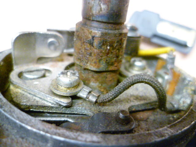
i kinda like the way your ground wire runs to the other side of the points. I wasn't completely comfortable with the way they were sharing a slotted hole on the points with the big washer AND the electrical connection. After seeing your pics, I'm thinking that wire should go to the other points screw like you have yours.
-
Glad to help. So comparing your pic to what I have here, there are some other differences. I'm not sure which is correct, but the wiring inside my distributor is a little different than yours. On the inside of mine, the ground wire went to the other side of the points than yours, and I've got this yellow wire on the high side of the points. Functionally it doesn't matter where the ground wire goes, and I'm guessing that my yellow wire was put in by a previous owner. Here's what I got. Input on originality appreciated:

-
I think I like the five lug options better. I'm just messing around with proof of concept at this point.
-
Like this?
-
Hahaha!!! That's how I usually roll. Lurk in the shadows with this kind of stuff, but I'm getting pulled out into the daylight. Aaaaaa!! It burns!
-
Yes, I know about on-car rotor turning. But won't quite work for everything I need here. Haha! And I'm sure you could guess that things aren't totally obvious on my end. I'm clearly jumping the gun a little, but here's a little of what's going on here.
-
Thanks much! Scan isn't necessary, but your damaged passenger front sounds perfect. What are the chances that you're not too far from Philadelphia?
-
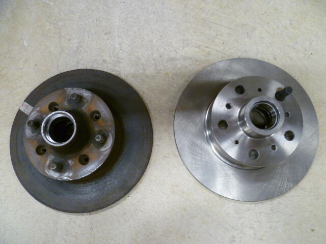
LOL! Thanks guys. It's a double secret project that I'm working on. But seriously, the short story is... I bought a cheap rotor off rock-auto. China's finest. And right out of the box, it's got over .010 runout. I was thinking that if I could figure out a way to fixture it ON a spindle and run it on wheel bearings, I could take a clean-up cut on it and bring it back to running true.
-
I have one available, but I'm in PA. Send me a private message if you're interested. Does it matter what year? I don't remember the year of what I have here.
-
Well having not messed in depth with the electronics inside the tach, I could be easily convinced that the wave SHAPE and DURATION are also important, not just the peak current. Point is... I can provide no assurance that the stock tach will be compatible with anything other than points.
-
I have performed this procedure on a few carbs, but I think only one set has seen the road. Reports are that set worked well. So I made a custom threaded piece of brass. Maybe you could find something generic instead of making something special. I put it in a position where it did not interfere with the hinge molded into the float, and I did not want to put it upwards into the bottom of the float because of gravity. Beyond that, I tried to put it into a "fail-safe" position on the float such that if it starts to work itself out of the float, it would hold the float closed instead of holding it open. Figuring that a float level too low would cause the engine to not run, while a float level stuck open could cause a fuel spill.
-
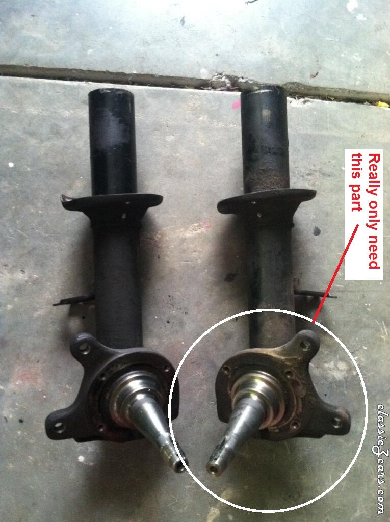
Anybody have a front spindle laying around they don't need? I only need one side, and it doesn't matter which side or which year. I just need the part where the hub mounts. I'm thinking if someone was working on coil-overs and accidentally cut off the tube too short or something? Or if there was a car that was in an accident and the tube is bent? Or someone who couldn't get the gland nut off and the threads are totally ruined?

-
Sounds good so far. As for the runout on the gear, the first thing I would do is look everything over under magnification and look for burrs / kicked up material (or anything else) that is interfering with the positioning. Maybe you'll get lucky and find something that can be easily dressed off or cleaned up to make things better.
-
I've heard people say that about you. Oh wait... That's not true at all.
-
Wait.... If this pic was taken before the crank was rotated to TDC, then there is nothing to be gleaned from it with regard to valve timing. Who cares where the cam timing marks are if the engine isn't at TDC?
-
Some questions... At the end of your previous thread, you verified the float bowl levesls with the clear tube wet-set method. 21 and 19mm, right? If so, that should be fine. Was there fuel in the return line back to the red jug? If so, then the pump is providing more than the carbs will take (at idle at least). But here's the rub... These engines really don't need a lot of fuel to idle. In fact, if you fill your bowl up to spec level and start the car with the fuel line completely disconnected, your car should idle for over 30 seconds before you suck the bowls dry. I'm thinking that you have enough fuel to the carbs at idle, but maybe not while driving. So... Couple things to look at. First, take it out for a drive and get it to die. When it dies, turn off the key and go out to the engine and pull the tube off the bottom of your float bowl. See how much fuel comes out. If you sucked the bowl down, you won't get much out. If you DID suck the bowl down, then it's a fuel delivery issue. Have you checked the little screen filters inside the banjo bolts at the carbs? If they're clogged, the return line back to the jug will look full, but the carbs won't be getting fuel.