


Captain Obvious
Free Member
-
Joined
-
Last visited
Everything posted by Captain Obvious
-
 That's a cool idea. I remember we talked about activated charcoal and it's application in the plating realm, but I never thought it could be a simple as a fridge filter!
 -
I have some input. First, a little more detail about the PCV tube... One of the PCV valve's jobs is to meter the amount of air being pulled out of the crankcase, so it's not unmetered. It's reversed direction from the way it came from the factory, but only time will tell if that's acceptable or not. The wire tie on the throttle linkage is necessary because a PO has removed the "throttle opener" device. It's an emissions thing that reduces emissions during deceleration by holding the throttle open a tiny amount. With that device removed, the linkage connection point for it is loose and flopping around on the linkage. That wire just keeps it from flopping loose. It's ugly, but doesn't really cause a problem. The "right" way to fix it would be to reinstall a throttle opener system. As for the rod sticking out of the damper knob on the front carb? My guess is that's the end of the rod that is supposed to be pressed into the plastic on the underside of the cap. I suspect it has punctured all the way through and is now sticking out the top of the plastic cap. "How does such a thing happen?" You might ask... It can happen with a front fire rapidly causing a high pressure inside the intake manifold (probably caused by a lean running condition). That high pressure burst tries to rapidly push the suction piston up, but (just like they're supposed to do) the jiggly bits on the damper stalk try to slow the piston's upward rise. However, in this case, the explosion wins, the damper can't get out of the way fast enough, and the stalk blows out the top of the plastic cap.
-
Cool! The valve looks great. Don't forget to do a safety margin pull test on it. And can I borrow that fixture when you're done with it?
-
I was just into this area of my 77 (same as 78), and after being in there... I would say "Yes, but I think it will be a pain in the butt". Getting to the hardware is possible, but finicky. And I worry about damaging the springy horn contact. With pulling the steering wheel being so easy, I would just remove it. It's just so much easier.
-
And don't forget... Speaking of cars, of course:
-
Hi Kats, Does the plastic reservoir bottle accept the same kind of cap? I saw pictures with a white plastic cap, but I didn't see anything with a metal pressure relief cap installed on the plastic bottle. And also, have you confirmed that the plastic reservoir bottle was designed to contain the pressure involved?
-
CO2 is a clear colorless gas.
-
Wait... Nothing stupid?? Nothing? Am I supposed to live in a plastic bubble of good judgment for the next month?? I was supposed to go for a run with scissors today. Well that narrows it down some. I put Fiero seats in mine and it wasn't easy. I didn't have to bash the hump on the floor (BTW - it's for the catalytic converter on such equipped models), but I had all the same mounting issues. Not an easy project.
-
Looking forward to it greatly!!! Can't wait Bud!
-
Of course, that was when he let me get into his car and took me on a tour of the local brewpubs...
-
I've personally witnessed questionable judgment on his part.
-
Do you know your last name is almost an adverb?
-
So, I know it was Porsche, but what model? I've got a Boxster in the garage and I've already measured the seats. Boy... Would SWMBO sure be surprised if she went out one day and found her seats weren't in her car anymore!! PS - Sorry, OP for the thread jack. I think we're almost done.
-
It's bearing bronze, not brass. Still not as hard as steel, but you just don't want dust or grit in there mixing with the grease becoming a lapping paste. Who knows... All that steering on the twisty roads in the mountains of SC? Couple years and you'll have no rack left.
-
Nice freehand work on that lube groove! Make triple sure you get all the burrs rounded off and get all the swarf out.
-
Thread jack alert... Pics or it didn't happen. PS - Glad you're still around and it's good to hear from you!!
-
Sweet! My first car was a beat up Falcon with a 170 and 3 on the tree. Unsynchronized first gear. I learned a lot about transmissions with that car. A whole lot...
-
It should be pretty easy to determine what size bolts are supposed to be used there. If I had to guess, I would say they should all be M12. There was a drawing floating around here somewhere that called out all the sizes for the suspension bolts. Have you seen that?
-
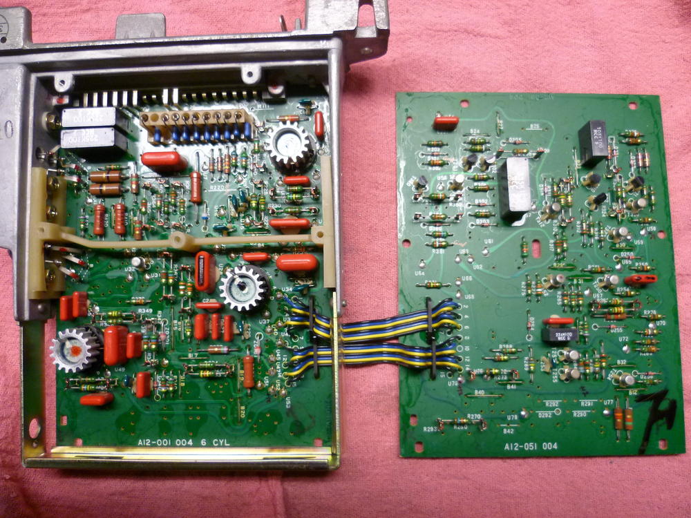
You are correct. Those pins go nowhere. Even though the connector is populated, those pins are no-connects. I'm thinking that they may have just received a shipment from Amp (the connector manufacturer) of connectors that had all the positions loaded instead of the partially populated versions they had used in the past. Reason being... I've got pics from later built ECUs that went back to the partially populated connector. Seems the fully populated ones were a temporary thing? That sort of thing is a pretty common occurrence in manufacturing. The buyer places an order and the vendor asks if they can substitute a different (but compatible) part instead. Usually because of lead time. If it's acceptable with the buyer, they get the substitute. May be what happened here. Reason I say this... Here's an ECU which I believe is built later than the one you posted above and it's got the partially loaded connector. I believe the later construction date based on three things... The ID numbers on the boards are higher. The plastic encapsulated capacitors in some locations (newer style), and the different heat sink style on the IC's. I bought this ECU used as a spare, and I was told it was for 77. I really have no way to verify that though. It may have actually came out of a 78. Anyway, all this is academic... Use the ECU that works. The number of pins populated really doesn't matter much.
-
Haha! Well just because it's reasonable, it doesn't guarantee accuracy. I could be all wet! Out of curiosity... Can you pop the lid on that 78 ECU and take a pic of the electronics inside?
-
Are you sure those M11 threads are native? Are you sure they are cut directly into the strut housing and it's not some sort of an insert or helicoil or something? M11 is a real thread, but it's a little unusual.
-
When I first ordered my Escort core ( SPECTRA PREMIUM 94741), I got a copper one like that. But what I really wanted was one of the aluminum ones. I opened a ticket with them and exchanged it for an aluminum one. Not sure it really matters, but I had already cut and sized everything for the aluminum version. If you're haven't made any mods yet, it might not matter. But for me, I wanted the other one. Apparently they consider the two form, fit and function identical. I'm not sure I agree...
-
Maybe anyone browsing the forum without being logged in appears as a guest? I'm thinking it could be legitimate members that simply hasn't signed in. I often browse the forum without going through the exercise of logging in... It's easier. I only log in when I have something to say.
-
I wouldn't get too hung up on the number of populated pins. From what I've seen, some of it may depend on when (and by whom), the ECU was assembled. The original first run ECUs seem to have only the used positions populated, but I've seen second source (or later replacement production units) that have all the positions populated. I think there are a number of factors at play with that. I remember someone's assembly that used plastic DIP packages inside instead of the old spider legged cans? Wheee's maybe? Definitely a later production run after the 280Z was no longer being sold new. Probably newer production of the old design for repair business.
-
There is lots of expert help already on the case, so I'm going to stay in the wings as much as possible, but before I go back to my hiding spot, there are two things that have caught my eye. First is this... On your to-do list was to return the AFM gear to it's original position by turning it six teeth counter-clockwise. The implication of this is that you had previously turned the gear six teeth clockwise. (Haha! Big intellectual leap by me, huh?) The POINT is... If think you are chasing a lean condition, then turning the AFM gear CW will only make it leaner: The second thing that caught my eye was the way you have the vacuum gauge and the vacuum advance connected. Something is wrong with the following: The vacuum advance signal for the distributor is not supposed to come directly off the intake manifold. It is supposed to come off a ported source from the bottom of the throttle body. And that vacuum source should be zero vacuum at idle. So something is screwy there, and your fuel pressure readings and ignition timing numbers are suspect until you get to the bottom of that. If you have the distributor connected directly to the intake manifold, then your base timing is wrong. Or if you have the vacuum gauge connected to the ported vacuum source, then your throttle plate is open waaaaaaaay too far at idle. Potentially because the thing just won't run at anything less. Also, if you're using that ported source for the gauge, then your FPR numbers may be correct because you can't do the subtraction for manifold vacuum correctly. And I agree with Zed Head... It just don't sound right and I agree that you need to double check the firing order. Also check the injector clickety-clicking with a stethoscope.


