


Captain Obvious
Free Member
-
Joined
-
Last visited
Everything posted by Captain Obvious
-
 Are you really sure you lost that much oil? That's an awful lot!! Especially under normal driving conditions. Typically intake valve seal leakage is worst when coasting and the intake manifold vacuum peaks. But under normal driving conditions, that doesn't happen all the time, just sporadically. I'm going to throw out a scenario.... You checked your oil before you started your motor and went on your drive. The level looked good. However, unbeknownst to you, the night before, your anti-drainback valve on your oil filter leaked and some of the oil typically held in your filter drained back into the crankcase. Then you went on your 50 mile drive and checked your oil shortly upon returning. At that time, you found you were about a half quart down. I would propose that it may not have burned away, but maybe just shifted locations? I've seen this scenario occur and just trying to get to the root issue before you go stuffing rope everywhere.
 -
I believe this is what @Zed Head refers to as "hooning" Did I say that right?
-
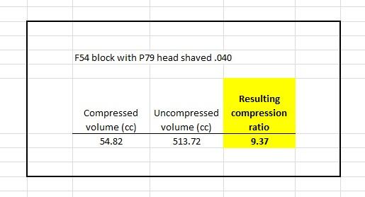
So I went back and found my notes. I was aiming for about 9.4 compression ratio. I'm running an F54 block with stock flat top pistons and a P79 head that has been shaved .040.
-
I'm not sure I understand what you mean by "smaller pipe". There are three connections to the device... One small (1/8 inch?) control connection, and two larger (5/8 inch?) connections. I thought the two larger connections were the same size at about 5/8 inch? That's not the case?
-
I did calculate it as I designed the concept, but I don't remember the number. I'll dig up my notes and see what I was thinking. I don't think it was in the 10's. I think I was aiming for mid to high nines. I probably should have had that info handy before I posted that pic. Sorry.
I'm no materials guy, but my expectation is you would certainly not want to temper a spring. If the wire is already malleable enough that you could cold form that wire into the spring shape (without snapping the wire because it's too brittle / hard), then tempering would just remove the springiness of the spring. It would be an ex-spring.
Pedantic, but looking at the intake tract, I'm thinking 73. It's clearly a converted flat top system.
I used the rope stuffed in through the spark plug hole method. I didn't trust that my tired old rings were up to the task of using compressed air. I wanted something of positive volume in there. Besides... I work slow. And the rope doesn't care.
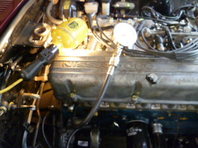
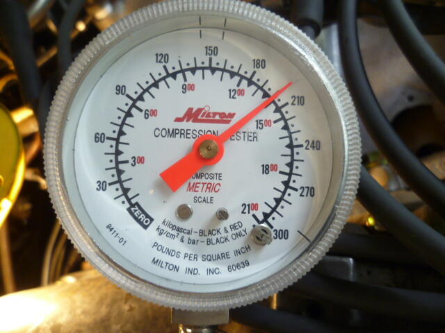
Yup. They are all 200-210, and I'm pretty happy with that. That's the motor I have been building (for way too long!) for my 77 280Z. It went around the big country block yesterday!! Then that compression test was when I got back. Looking good so far! I got one cylinder running cooler than the other five, and I'm not sure yet what's going on with that, but I'm pretty happy. I haven't opened it up WOT yet on the road yet. Want to give the rings time to seat without making anything angry.
Yeah. I have no idea what's going on with that antenna connector pigtail on my car. It looks factory, but it doesn't make sense.
Haha!! Unfortunately, that's probably exactly what happened!
Your place was a hammer farm back in the old days?
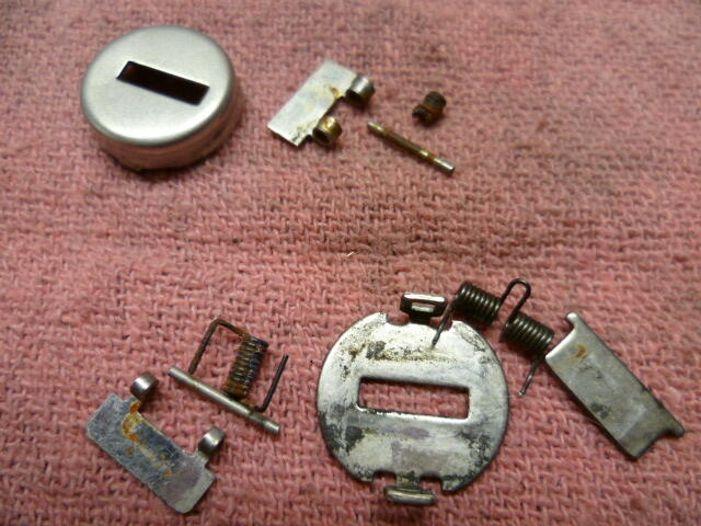
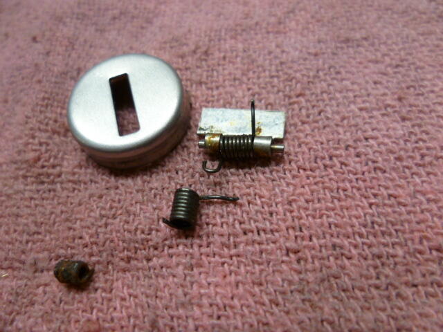
And about the spring... My spring was a little rusty nugget. Pretty much nothing left. I got a couple locks from junkers and adapted one of them to fit my lock. Unfortunately, I don't remember what the donor car was, which makes the suggestion mostly useless. But, here's a pic. My rusty nugget of what's left of my original spring is at the top, and two donor springs in the foreground: I ended up cutting the "double" spring into two pieces and using half of that one. Again, my original nugget in the lower left:
 You are correct. None of those marks on either side of the main groove are supposed to be there. And JB weld will fill in the grooves, but best case, I don't think it will last long. And worst case, as it wears away, it gums up the works. I would just do the best you can with what you have and pretend you never saw those small grooves in the first place. I mean... If someone wants to break into the car, that lock won't stop them, even if it's new.
The radio I have is from a later year. It has the later (horizontal) antenna switch design. I assume a PO changed it out at sometime in the past.
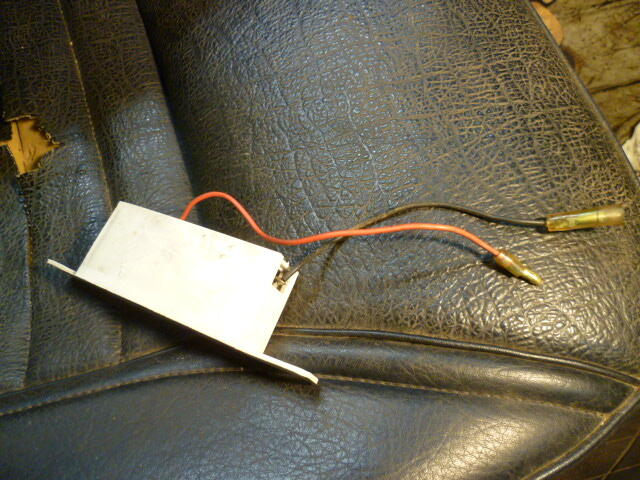
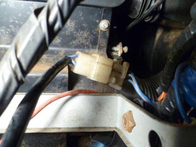
Here's some pics of what I have here. These are from a mid 70's car. Map light connections on the car side: : And on the light side: Here's the lighter: And here's what I believe is my antenna switch connections? Seems I have a pigtail leading into the three position connector everyone seems to have? This might be an early car thing?
You are correct. None of those marks on either side of the main groove are supposed to be there. And JB weld will fill in the grooves, but best case, I don't think it will last long. And worst case, as it wears away, it gums up the works. I would just do the best you can with what you have and pretend you never saw those small grooves in the first place. I mean... If someone wants to break into the car, that lock won't stop them, even if it's new.
The radio I have is from a later year. It has the later (horizontal) antenna switch design. I assume a PO changed it out at sometime in the past.
Here's some pics of what I have here. These are from a mid 70's car. Map light connections on the car side: : And on the light side: Here's the lighter: And here's what I believe is my antenna switch connections? Seems I have a pigtail leading into the three position connector everyone seems to have? This might be an early car thing?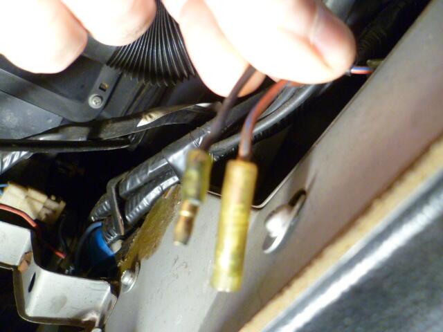


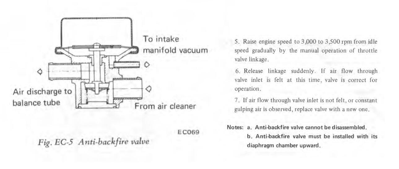
 The anti-backfire valve is supposed to be closed tight shut when there is no vacuum on the control signal port. If you apply enough vacuum to the small control port, the valve should open and pass air between the two large hose connections. And the control port should hold vacuum and not leak down, but I have seen them function "well enough" even with a small leak in the control cavity. Bottom line... It sounds to me that you unfortunately have two failed AB valves there. Neither of them are any good.
Understood. But it's a matter of AVAILABILITY, not performance. There is no performance change at all. It's more of an "unfortunate necessary substitution driven by inability to get the better fitting part". The OP asked if the 73-76 cylinders were a good upgrade, and I believe the answer is "no". I'm not trying to cause any trouble here.
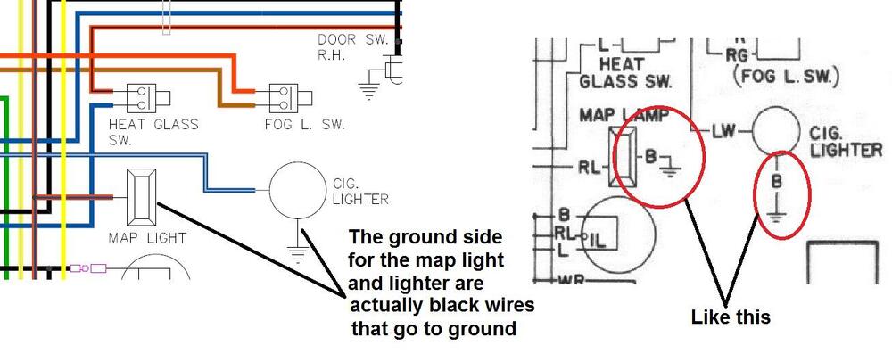
Chas, I took a couple pics of the radio area and will post them when I get a chance. In the meantime, here are a few things to look at: First, As drawn. there is no power being supplied to the accessory relay or ignition switch. You need a connection dot on the W/R wire: Second, the map light and lighter have black wires coming off them to make connection to ground. I have pics of these wires, but they were never shown well on the original documentation: Third, maybe I'm misunderstanding the intent of your drawing, but it appears the heater blower motor appears twice in two different shapes:
The anti-backfire valve is supposed to be closed tight shut when there is no vacuum on the control signal port. If you apply enough vacuum to the small control port, the valve should open and pass air between the two large hose connections. And the control port should hold vacuum and not leak down, but I have seen them function "well enough" even with a small leak in the control cavity. Bottom line... It sounds to me that you unfortunately have two failed AB valves there. Neither of them are any good.
Understood. But it's a matter of AVAILABILITY, not performance. There is no performance change at all. It's more of an "unfortunate necessary substitution driven by inability to get the better fitting part". The OP asked if the 73-76 cylinders were a good upgrade, and I believe the answer is "no". I'm not trying to cause any trouble here.
Chas, I took a couple pics of the radio area and will post them when I get a chance. In the meantime, here are a few things to look at: First, As drawn. there is no power being supplied to the accessory relay or ignition switch. You need a connection dot on the W/R wire: Second, the map light and lighter have black wires coming off them to make connection to ground. I have pics of these wires, but they were never shown well on the original documentation: Third, maybe I'm misunderstanding the intent of your drawing, but it appears the heater blower motor appears twice in two different shapes: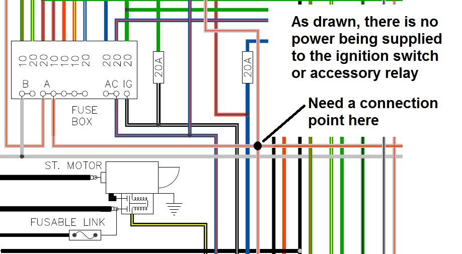
 I'm not totally sure I understand the question, so I'm just gonna shotgun a little: It's not 73 and up. It's actually 73 to 76. In 77, they changed the wheel cylinders dramatically. So... If your question is "Should I change to the 73-76 cylinders?", then my answer is "No. There is no "upgrade" to making that change at all." So unless there is something wrong with your current cylinders, there is nothing to be gained by changing to the 73-76 style. And if your question is "Should I change to the 77-78 style cylinders?", then my answer is "The 77-78 style cylinders are way better than any of the previous years, but changing over to them is not an easy conversion."
First, some answers... For the 71 four-screw lids, You should be using the 18.5mm long valves. So what you are using there sounds fine. The target float level for the 71 lids is 20mm below the lid, but I believe anything close (18-22) should be fine. When I went through the same thing, the only solution I could come up with was to add weight to the floats. This 4g brass plug threaded into the side of the float worked well:
I'm not totally sure I understand the question, so I'm just gonna shotgun a little: It's not 73 and up. It's actually 73 to 76. In 77, they changed the wheel cylinders dramatically. So... If your question is "Should I change to the 73-76 cylinders?", then my answer is "No. There is no "upgrade" to making that change at all." So unless there is something wrong with your current cylinders, there is nothing to be gained by changing to the 73-76 style. And if your question is "Should I change to the 77-78 style cylinders?", then my answer is "The 77-78 style cylinders are way better than any of the previous years, but changing over to them is not an easy conversion."
First, some answers... For the 71 four-screw lids, You should be using the 18.5mm long valves. So what you are using there sounds fine. The target float level for the 71 lids is 20mm below the lid, but I believe anything close (18-22) should be fine. When I went through the same thing, the only solution I could come up with was to add weight to the floats. This 4g brass plug threaded into the side of the float worked well: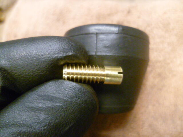 Thanks Chas. I looked through my pics and don't have anything good, but I believe the three connections to the antenna switch are three independent spade connectors on three loose wires. I'll confirm when I get a chance unless someone beats me to it. I'll work on the "vintage" style diagram and you can work up the "new style color" version. Might just be me, but I'm finding working on an early car is enjoyable using an early wiring diagram. Cleaned up and corrected, of course. Kinda quirky. So how would you like me to communicate mistakes on your diagram? Screen shots? For example, like this:
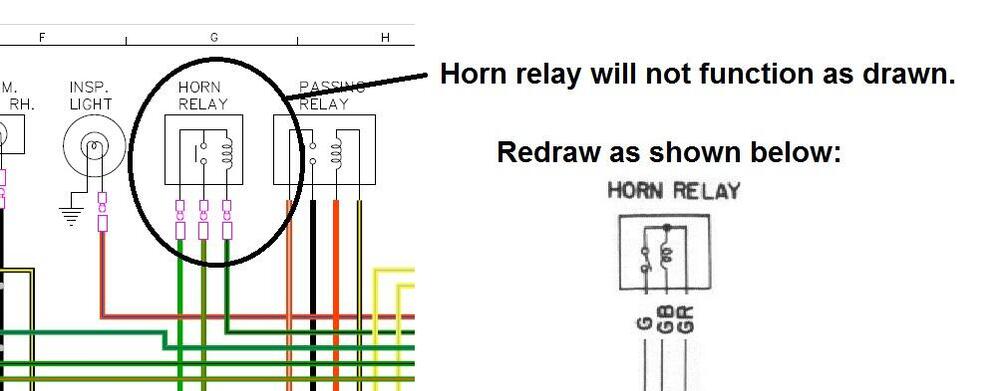 Thanks Steve. I'll make that clear on my wiring diagram when I'm making the next batch of changes.


Important Information
By using this site, you agree to our Privacy Policy and Guidelines. We have placed cookies on your device to help make this website better. You can adjust your cookie settings, otherwise we'll assume you're okay to continue.