Captain Obvious
Free Member
-
Joined
-
Last visited
Everything posted by Captain Obvious
-
 Here's a rough chart that can give you an idea of the relative hardness of rubber and poly: My thought on poly replacements is they are (obviously) better than nothing, but will never be as compliant (or quiet) as the original system. With the original system, the only points of contact are through the rubber bridge of the bushing, and the raised tips of the rubber on the flat washers. With poly, you usually have much more contact. At least that's the case with the current design poly bushings. Also, I'm not sure about the flexing abilities of poly. By that, I mean, I know what happens to rubber when it flexes and flexes and flexes a whole bunch of times... Pretty much nothing. But what happens to poly when you flex it a couple thousand times? I suspect it cracks a lot more readily than rubber of the same durometer. So the tipping point would be to make it as soft as possible without it being soft enough to bend enough in application to cause it to fatigue and crack.
 -
I thought we just went through this? In this thread: http://www.classiczcars.com/topic/58037-mustache-bar-bushings/?do=findComment&comment=525900
-
-
Have you ever had a complete failure of half the system while driving? I never have, but somehow I just doubt I would have the wherewithal to pump the brakes to shuttle the plunger to the end: Pedal goes to the floor. Brain goes "OH SHITE!!" and I freeze looking for an exit path. Foot planted hard on the floor. In fact, at that point, I'm probably trying to push the pedal THROUGH the floor. Brain never goes "Just pump the brakes a couple times to shuttle that plunger to the end of travel and you'll get some pressure back".
-
The first block (the one closest to the master cylinder) is the brake warning switch. It doesn't proportion, it just lights the warning light if there's a failure in one axle of the system. The second block (the one on the firewall) does the proportioning. It's a little weird looking, but since the warning switch is mounted close to the LF wheel, they pulled the line off there to go to that corner. The pressure there will be the same as the RF, but it was just easier to pull the plumbing connection off there instead of pulling another front connection off the proportioning valve and backtracking to the LF corner.
-
I agree (in that there is so little that's adjustable), that I did mine myself too. And I didn't even bother with string and jack stands. I had new tires and just measured the distance between treads at fore and aft of the front tires. Here's my thought process... I can easily adjust the toe to something close to correct, and then I can then fiddle with the toe settings same on both sides until I get the steering wheel straight. After that, the car should go straight and the steering wheel should be positioned correctly. If the car handles well (which mine does), and the tire wear is acceptable and even (which mine is), I'm claiming victory. What this method does NOT do is make you aware of any issues like what you had done with the bushings or issues with the rear wheels. Those issues would show themselves in handling issues (like your squirrely feeling), or badly worn uneven tires. And the problem with counting on tire wear to illustrate an issue is that by the time you know, it's too late. So, I got lucky... My car drives straight, handles well, and the tires are wearing slowly and evenly. I don't know (or need to know) what's going on with the more complicated facets of the alignment. I don't know if my camber or caster is the same between sides. I don't know if my rear toes are the same. Doesn't matter. Might matter if I was driving on the track at the limits of handling, but I'm not. Goes straight, handles well, tires wear even and at a reasonable rate. Done.
-
So they didn't pick up on that while on the alignment rack? You could probably adjust that out for toe, but everything else would be out of whack, right?
-
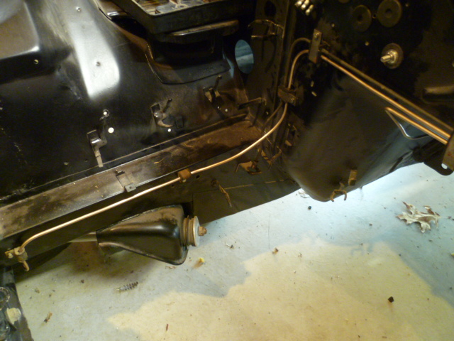
I figured it was flush. Just had to ask. So have you got any pics of the pickup installed?
-
I saw that too, and I think that might be a California thing. You can also see the "Floor Temp" warning lamp that only came on the CA cars.
-
-
Haha!! Exactly. I have two in a baggie here somewhere. Bought them about a year ago and haven't gotten around to finishing the job! 8491A202 Hardened drill bushing- .375+ id, .625+ od, .375 long You're a smart guy!
-
Did that happen at Hybrid as well? I remember that on Zcar... Very unpleasant.
-
-
I've sectioned an original shift knob into a couple pieces, and after seeing the inside (the part that has never seen the sun), I believe the knobs are made out of the same material and color as the steering wheels. On the inside, they are much more tinted toward red than they are on the outside. Homogeneous throughout, and red. When I get a chance, I'll snap a pic or two.
-
Nice work. So where did you source the new door detent rollers? I would really like to do this too, but it's lower on the priority list. I've already identified something from McMaster that I think would work, but if you've got something genuine, then that might be even better. What'cha got?
-
Nice. I like the trigger wheel. I've given some thought to running coil on plug, but I don't currently have any way to sequence them properly. One question about that wheel... Are you sure it's sitting completely flush against the back of the damper assembly? It looks like the metal tabs may be overlapping the rubber joint. Can't tell from the pics if there's a raised bump or anything there that may be causing some interference.
-
Excellent. Glad it was that simple. Now put a relay on your starter.
-
-
The intermittent START signal is probably because you have eaten up the internal contacts with the current drawn by the starter solenoid. It'll happen again to your new replacement. You might not be around anymore, but it'll happen. I put a relay between the switch and the starter.
-
Haha! Thanks guys. Site, you should see my fingers in the winter! In the winter, they spontaneously crack! And I don't think I could ever be a teacher. I doubt I would have the patience for the people who really didn't want to be there.
-
-
And here's a quick video of this pin retained prototype rig. I think I need a better video camera:
-
Hi Kats, Here's another concept for the lug nuts. I don't think this is what they did (I think they forged it into place), but if you really want to completely hide the retaining feature to confuse your competition, here's one way I came up with to do that. Again, since this is proof of concept only, I took shortcuts. Most noticeably, I did not make a tapered ring this time, but instead just used a simple cylindrical collar as it was much easier and does not affect the viability of the test. I cut a groove on the inside of the collar and drilled two holes through the "nut" body: I then pressed two small pins into the body: I pressed the pins flush with the outside diameter of the body: The lengths of the pins are such that when pressed flush with the outside, they protrude into the inner portion of the body: I made a mandrel a few thousandths smaller than the ID of the nut body and tapered it on the end. I used a portion of an old bolt because it has a quality heat treat of at least grade 8.8: While the pins are flush with the outside, slip the collar over the body, put the mandrel in place, and press the mandrel into the part on the arbor press. When you do this, it forces the two small pins outward and they catch the groove in the collar: Thread the ID and you've got a retained collar with no externally visible retaining feature: I still think they forged it, but it was nice to see this more elegant method work.
-
Thanks Kats. I don't think I'm qualified to make real ones though. Material selection (for real), heat treating, plating... Those are the difficult parts for me. If I get a few more moments, I'll test the other (less likely) retention theories I mentioned before. I'm sure I can come up with an internal hidden retention pin, but the one I'm really curious about is the differential temperature assembly. That would be really neat if I could get that to work!
-
Fantastic! I'm so glad I got a chance to see the original carcass before the work began. Gives me a greater sense of the amount of work you went through. Now all I have to do is see it now that it's done! So one question though... What are you going to do now? Your wife probably doesn't want you in the house that much. Has she started suggesting other projects or hobbies for you?