


Captain Obvious
Free Member
-
Joined
-
Last visited
Everything posted by Captain Obvious
-
 Thanks for checking Zed Head, and thanks for the pic of the 81 cover. Chickenman, I know the stock system works well. A little ashamed to admit it, but the only reason I've even entertained this idea is simply aesthetics. Here's my thinking... I've got a FI car, and currently the PCV valve screws into the underside of the intake manifold. If I were to relocate the PCV to the engine side of the intake manifold (instead of the bottom), then I could connect a short tube from the valve cover to the relocated PCV valve*. That tube wouldn't even have to cross the fuel rail. It could go under/behind the fuel rail instead. Then for the block end connection, I could run a short piece of tube from the block to a nipple on the underside of the rubber intake boot that connects the AFM to the throttle body. The whole thing would be so much cleaner and simpler than the existing system. I wouldn't have those long large PCV tubes running across the top of the engine all the way from the valve cover up to the throttle body. * As a side note, there's even a threaded hole (plugged with an allen headed plug) in the intake manifold down between the runners for cylinders 3 and 4. It connects into the shared internal passageway for the EGR system. It's almost as if Nissan had considered exactly what I'm suggesting. From this old thread http://www.classiczcars.com/topic/22366-efi-progress-on-my-datsun-240k/ here's a couple pics of the integral EGR passageway built into the intake manifold. This one is webbed (which mine is not), but the concept and location of the passageway is the same. He's removing the EGR passageway completely to clean up the look of his intake manifold: In this pic, you can see the flat boss cast passageway between 3 and 4. The boss was never drilled and plugged like the earlier ones were though. But the boss still exists:
 -
I'm not sure they were expecting "a lot of blowby"... I think it's just the nature of the design. The rings are never a perfect seal, so the amount of blowby lost past the rings will probably be proportionate to the pressure of the explosion. In other words, the amount of blowby will be proportional to the load the engine is being asked to support. Couple that with decreased intake manifold vacuum at high load conditions, and the direction changes. You make it sound like they were expecting higher blowby only on worn engines and I don't know if it was your intention, but I don't think that's the case. Short story? I think the flow direction will change even on a new healthy engine. At idle, air flows into the valve cover nipple, but at higher blowby conditions, that blowby will flow OUT of the valve cover nipple. The original purpose of this thread was to entertain the idea of reversing the default flow direction of the whole system so the "reversed" direction of that upper tube would become the "normal" direction instead. This would also mean that the block connection under the distributor would become the fresh air replace except under high blowby conditions.
-
Sounds great. I'm hoping my suspension work outlasts me as well. Next time I'm down there again, we'll have to go for another cruise!
-
LOL!!!
-
Thanks for the thoughts Zed Head. Note the direction of flow in those diagrams... Metered Into the intake manifold by the PCV and then replaced by clean fresh air pulled into the valve cover nipple. That's the "at idle" flow direction. That direction would probably reverse direction under heavy foot high blow-by conditions, but at idle, the nipple on the valve cover is fresh air in. On the carbureted cars you ought to be able to pull the hose off the valve cover and the nipple on the cover should pull a slight vacuum. Cap it off for a couple seconds and let vacuum build up in the block. Then it will woosh back in when you unplug the hole. You could do the same thing on the EFI cars, but it'll throw off the air metering system. Also an interesting thought about potential changes in the design of the baffle over the years. If you've got easy access to something newer, it would be interesting to see if you find the design the same. Site, I think stainless steel would be a better idea than plastic. Stainless sink scrubby? Or stainless steel wool:
-
That's beautiful. I wish I could justify the cost... I'd love to have my dash redone. It's still "not too bad", but it's just a matter of time before the grand canyon opens up.
-
Excellent! Did you pickup a cheap hydraulic press? So how does it feel compared to before? Feel better? Also, did you normalize all the rubber bushings with the suspension loaded?
-
So.... Is that Lorena?
-
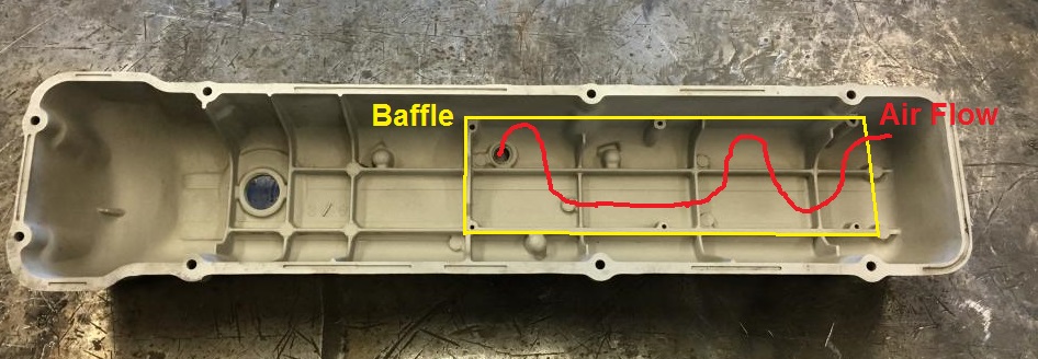
Using your pics, I whipped up a (very) crude sketch of how I think the baffle works. How does this look to you?
-
-
Excellent! Thanks for the pics!! So with the original baffle, the air travels into (or out of) the rear of the baffle, up and over the two humps in the baffle and finds it's way to the original tube connection about midway in the valve cover. The bumps in the baffle and cast ribs are the labyrinth that is supposed to separate liquid from vapor. And the general consensus is that the original factory baffle does a pretty good job of doing just that?
-
Sorry to hear about this. RIP.
-
-
Or both!!
-
bjreed1119, Dave is correct in that there are no permanent magnets involved, just a steel plunger that is pulled by the electromagnetic coil. With that in mind, the polarity doesn't matter. Only thing that I might wonder academically about is that there may be some small amount of residual magnetism retained in the injectors after being used in one direction for some time. Not sure how much of an effect that might have, or how long it might last until the fields have been readjusted. When I redid my harness, I found most (but not all) of the injectors were wired the same polarity. So when I rebuilt things, I wired them all the same, using the predominant polarity. I think I kept four the same and switched the remaining two to match the other four.
-
Wow! Damn you're good!!
-
Thanks!! If you want to, you can put that pic both here and in the thread where I was talking about changing the PCV direction. I'm still thinking about changing the PCV scheme, and that's why I wanted a peek at the baffle design(s). http://www.classiczcars.com/topic/57136-pcv-flow-direction-can-i-reverse/
-
Haha! I don't know if the other owners with those kinds of cars like the association or not. I guess it would depend on the association. On a related note, I went to a show a couple weeks ago and there were maybe thirty DeLoreans there. And almost all had some sort of reference to the Back To The Future movies. Looking very hard, I think I found three of the thirty on which I could find no reference to the movies.
-
Cool! So it was just a bum rebuilt alternator? Man how I hate rebuilds...
-
-
Welcome to the club, but wow....... That thing has been hacked, jacked, and molested!! You either better be really really good with electrical troubleshooting yourself, or you better find someone else who is. I suspect that thing is going to take a lot of effort to get into a running safe state of reliability. I think you should be happy that it wouldn't start. I'd be worried about simply connecting the battery up without something catching fire. Buy a decent meter and learn how to use it!! And you're going to love the car once you get stuff sorted out!
-
I'm thinking Pursuit Interceptor:
-
I am so hungry right now!!!
-
I don't think you would be able to convince anyone that what I did was a Datsun factory-recommended replacement. Sounds like you either need to find the "correct" drop in parts, or find a shop that's interested in doing custom work. My old stock fitting heater core leaked a little, but I'm sure it's easily fixable by someone trained in the art. Would that help you out at all?
-
Yup. That's what my blade holders look like. Thanks for the pic. I gave my arms a good lookover and found small residue areas of black paint on the underside in the corners. So my suspicion is that they used to be black, and somewhere sometime along the way, that changed. Either it wore off over the years, or my PO bead blasted it off and missed some small spots on the back. In any event, the mystery is over, and my arms "should" be black. Thanks again everyone for the input!