


Captain Obvious
Free Member
-
Joined
-
Last visited
Everything posted by Captain Obvious
-
 Yikes. Yeah, that sleeve has seen better days! And I'm assuming there was corresponding wear on the bushings as well. The original bushings are oil impregnated sintered material, but mine looks like there is also grease in the groove between the two bushings. Yours was clearly beyond salvage and I'm glad your repair job fixed you up! I'm hoping with fresh new grease on mine, I can leave that part of my pedal alone.
 -
Will do. As soon as I know that this whole thing isn't a disastrous failure. Parts on order...
-
Sorry I missed the show. I was working on a Z... That counts a little!
-
Got it, thanks. I've got a goal now!!
-
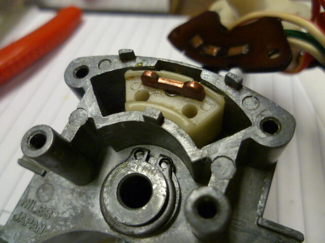
Are you talking about the little brass piece that fits in the slot in the plastic block?
-
Have you got a pic of the part you lost?
-
Excellent, thanks! With your pics as guidance, I took a good look at the bushings on mine, and I think they are ok. I will clean them up good and start again with fresh grease. I think all of my pedal issues are up at the clevis. Working on clevis stuff in this other thread: https://www.classiczcars.com/forums/topic/60310-squeaky-clutch-pedal-and-clevis-pin/#comment-665374
-
-
Thanks. So the router bearing you used was a ball bearing, not a sleeve, right?
-
@jwtaylor, I know it's unlikely, but do you have any pics of this process? I'm guessing if you had any, they would have been posted as part of this thread already, but couldn't hurt to ask.
-
@zKars, I've got the clutch pedal out of my 280 at this very moment, and no surprise, the clevis pin and it's associated hole in the pedal is worn and needs to be addressed. Not as bad as what 2377kN found, but bad enough that it's time to do something about it. Have you got any pics of your solution where you installed a bearing into the pedal hole? I'm hoping you could save me from reinventing the wheel here. I mean, I could certainly just bore out the hole and use a larger clevis pin, but a bearing... That's sweet.
-
Hahaha!!
-
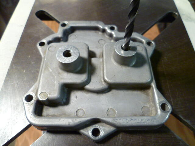
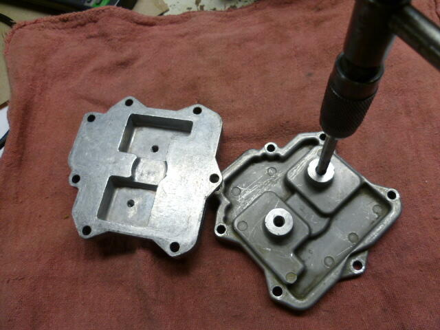
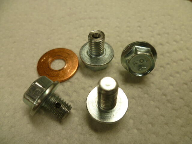
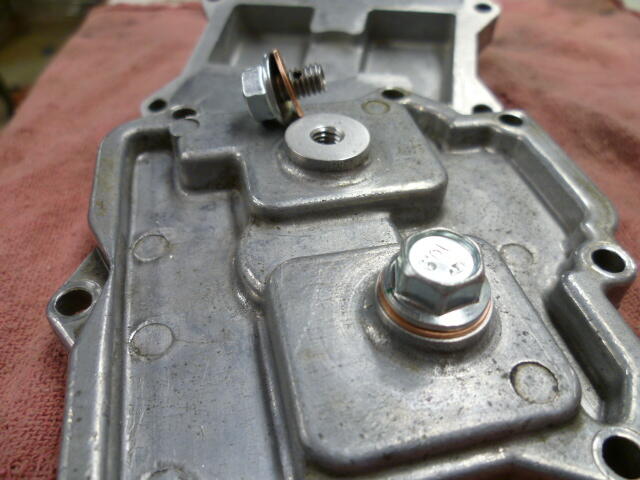
Sigh... You really want bowl drains? This happened many moons ago...

-
Oh great. Now what's Cliff gonna do????
-
Yes, it's normal. What is this "easy" thing you talk about? Working on cars is hard.
-
"Wake The Sleeping Beast" or something like that. @siteunseen will be along in a moment to point you to the correct thread.
-
Were you there last year? And if so, did you have your Z, or were you in one of the other cars in the stable?
-
Awww man. I usually go to that show, but I'm not gonna make it this year! Kinda snuck up on me, and I just can't swing it. Aaaaargh. Would have really enjoyed meeting you.
-
I'm a fan of the flat tops, but they are more complicated than the round top. And complicated is not "the easiest way". I'd suggest taking the entire intake manifold(s) off and replacing it with the round top rig you have there.
-
There is no drain on the flat tops.
-
duplicate
-
Me too. Glad the work was successful.
-
I'll go out on a limb and say they didn't, just the last one. The other two probably worked fine, but we spent ten pages trying to solve multiple problems at the same time instead of breaking it into simpler, easier to diagnose parts. Back when the other distributers were in there, the coil wasn't getting power like it should have. So no spark, but because of problems upstream, not the distributer. Then by the time we finally hotwired the thing, we had installed a bad distributer. That's my read.
-
Try this... 1) Take the valve cover off. 2) Use a screwdriver to set cylinder #1 at TDC while the two front lobes are pointing up. 3) Look at the timing notch on the crank pulley. It should be pointing at zero. At that point, your distributor rotor is pointing at #1 cylinder spark plug wire. If the rotor is pointing at some crazy direction like 8:30, it means that someone put your oil pump drive shaft in the wrong position. You can either simply readjust the spark plug wires to put wire going to #1 at the same crazy angle where the rotor is pointing, or you can drop the oil pump and realign it to where it SHOULD be pointing. My suspicion is that someone dropped the oil pump in the past and when they reinstalled it, they had the engine on TDC #1, but were on the exhaust stroke instead of on #1 compression. I'll admit it... I've done it.
-
That all depends on the internal design of the ignition switch. Some of them are designed such that the power on the ON terminal drops out when you rotate the key to the START position, and some of them keep the ON terminal hot even when the key is in the START position. It's clear (from the behavior of the car in question) that he has a switch that does not drop out the ON connection, but in fact, keeps that connection hot even when the key is rotated to the START position. Depends on the car year and whether the switch is factory or has been replaced by aftermarket at some time in the past, etc.


