Captain Obvious
Free Member
-
Joined
-
Last visited
Everything posted by Captain Obvious
-
 When you run your oil pump with the drill, do you see a bunch of oil oozing out from around the cam journals?
 -
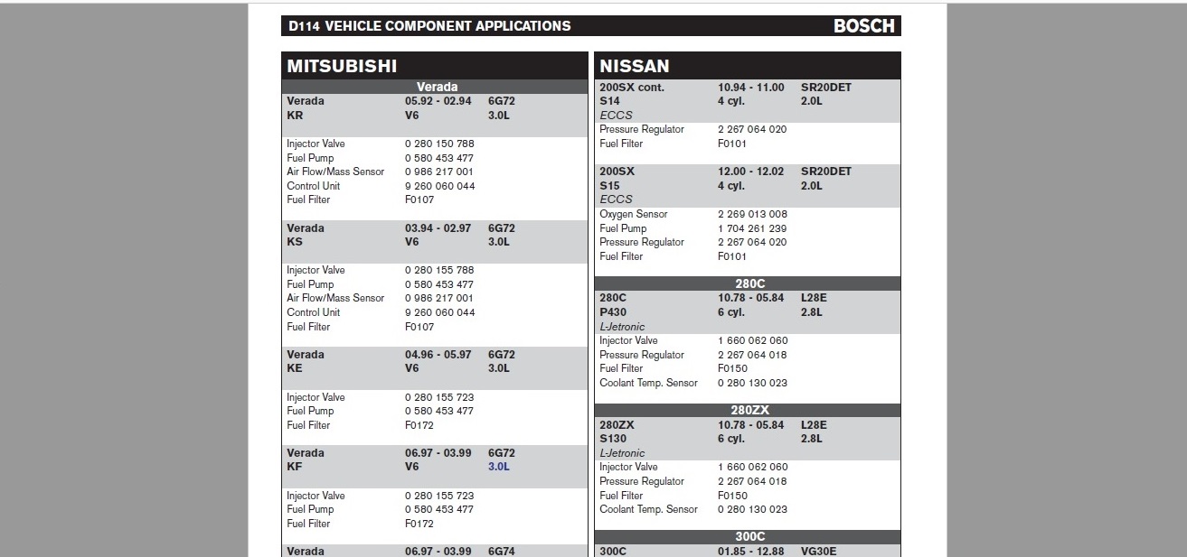
Oh, and to clarify... Do you have MORE temp/resistance points for the 028 than what you already posted above? The more, the better. 0 280 130 028: 8500-11500 @ 68ºF 770-1320 @ 176ºF
-
I couldn't dig up any data for the 028 on the web. Do you have temp/resistance points from the Volvo service manual for that sensor? The only reference I could find for that sensor in what I have here is that it was used on the Volvo 760. That's the only application data I could find. 760 02.82 - 04.86 V6 2.8L K-Jetronic (Lambda)Coolant Temp. Sensor 0 280 130 028 8/83>
-
Before you put the head back on, take a real good look to try to make sure the passages are clear in the head. Compressed air. Carb cleaner blast. Something. Also, you can take the lids off the distribution blocks on the spray bar and get a better straight on carb cleaner blast down into the tubes. Not sure if you did that, but if you are only getting a dribble out of the cam towers with the bar not even installed, then your problem is somewhere further upstream. So how about the obvious... Head gasket has the proper holes in it for oil to get up to the head? Cam tower shims without a hole in them? Cam towers installed in the correct orientation? (Is it even possible to put them in backwards?) Wadded up pieces of paper towel stuffed into the oil holes in the head so it didn't dribble all over your workbench?
-
That aluminum chunk is probably molded onto the splined shaft. And if that's the case, I don't think you would be able to get that shaft out without destroying the aluminum portion. There's probably a feature built into that steel shaft to insure that those two pieces rotate as one. Maybe some splines buried down in there or a square cross sectioned area or something. Cross pin. Something. So I still think the extendo collar is the first thing I would try. Either welded or set-screwed into place.
-
I'm really confused... You said "I love this method of de-rusting: gets into all the places I can’t with a brush!" But then you found all that rust inside!! I though it got into all the places??? Sorry, but I'm lost.
-
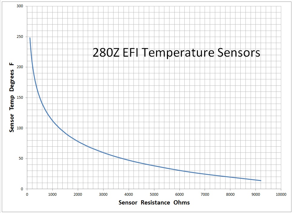
Here's an excerpt from an old Bosch catalog that indicates that the 280ZX (which is the same as the 280Z) uses the 0 280 130 023: And here's a chart I derived from the resistance points found in the Z service manuals:

-
I took a quick look at a window regulator yesterday and making a whole new part to replace the original shaft would be a large undertaking. Not only would you have to deal with the gear on the other end of the device, but the whole thing is riveted together originally and you would have to figure out a way to put it back together. I think there is enough length there to cut off the original and put in an extendo collar. The other things to look into would be "Is there enough room in the system to allow for the increase in diameter an extendo collar would cause?" In other words... Is there enough room to increase that diameter or will it hit the door frame or door panel or something? If there is clearance, I would try an extendo tube device of some sort. Make it a precision fit onto the old shaft diameter and use setscrews to hold it in place?
-
Haha! Nice fountain! You could do the same test again with the head installed but without the spray bar. See how much oil comes out sideways from the cam towers where the bar attaches. Should be a substantial amount just like your fountain.
-
And as for the mechanical gauge, I think you could put a couple wraps of teflon tape around the 1/8th-27NPT gauge and be OK enough for a test. It might seep a little at the joint, but not enough to affect the pressure reading. Just don't crank it down so much that you deform any metal on the threads. I would test fit one of your gauges and see if you get a couple good turns on the gauge before it starts to tighten up. If you get a couple turns, I think it will be fine for a temporary test.
-
I don't remember the difference offhand, but here's a pic showing the difference between the regular and the high flow:

-
Yes, because of the very small extension amount you're looking to achieve, it's inherently impossible to do that with an extension. The problem is the splined portion of the extendo one and the splined portion of the original shaft must share the same space, and that is impossible. So you're looking at a different solution. I'm not real keen on making a whole new shaft. I don't remember what is on the other end, but it might not be simple. I think I would try to "extending the existing shaft." Is there enough room to put in a short coupling collar? Or if not, a short piece of rod stock and weld the three parts back together. Or cut the original splined portion off completely and then make a new splined piece (like what you've already made) and slip it over the (now blunt) stub of the original shaft? Wouldn't stick out as far because you've cut some length off. Something like that.
-
Yeah, I wouldn't open up those oil restricter orifices at all. If everything is working as intended, there should be plenty of oil delivered to the cam lobes. Did you put a mechanical oil pressure gauge in the block and see what kind of oil pressure you're getting?
-
You got to be a little more enthusiastic with the success. You're hiding that little note under all the pics! How about this: "Woo Hoo!!! MY CLOCK WORKS!!!" That's what I would do.
-
You need something else to be aware of? That sender unit threads into a passageway inside the block. That passageway is not very deep and you run the risk that something you tap into the broken off stud bottoms out on the far side of that passageway. In other words... If you try to use an extractor in the hole in the middle, it's going to need to be sized carefully so that you don't bottom out the tip of the extractor inside the block before the teeth of said extractor bite in. I know... You really needed just one more complication in this whole ordeal.
-
The consensus, based on the comments above, is that the stub of material remaining in the block will come out easily if you could just get a hold of it, either on the inside or the outside. I, however, disagree with that consensus. That things is tapered threads and it's in there tight enough to snap itself off when you twisted the oil pressure sensor with a pair of vice-grips. It's not gonna come out without a fight. That thing was threaded in there tight enough to seal the pipe threads and snap off the sender unit. I don't think it's going to turn easy. It's certainly worth a try to use an extractor into the center hole, but I'm not confident that will work. Just don't snap off the extractor inside the remaining stub. Unfortunate.
-
To simply get the engine to run, the absolute positioning of the distributor driveshaft really doesn't matter. All you need to do is assure that the timing is correct. I would pull the plugs, put a timing light on it, and use the starter to spin the engine over. It should spin fast enough just like that to get a good reading off the timing light. If the ignition timing is correct, it doesn't really matter if the distributor shaft is a tooth off or not. You have accounted for it with the rotation of the distributor body. Of course, since it's been almost a day since you were looking into this, I assume you've already solved this issue, put new brakes on the rear, and powder coated the front control arms.
-
Actually the way you measured the zener voltage, you are almost spot on. You are at 4.94 V across the zener. So it won't start by itself, but what does it do if you give it a push start? Will it stay running, or does it come back to a stop? And if it does come to a stop (which I assume it will), does it stop in about the same amount of time as if there's no power applied at all? In other words.... Does it take longer to come to a stop when you give it a push with the power applied, or does it stop in the same amount of time whether there is power applied or not? Nice photography. But I'm thinking we shouldn't be surprised.
-
Cool. With your stash, you're already well on your way! So is that tantalum cap polarized? I don't see a polarity marking on it, but the tantalum caps I've worked with were. And if it is polarized, make sure you get the polarization correct. Tantalum caps really don't like to see reverse polarity, especially at temperature. I'm wondering (thinking?) that might be a ceramic cap and not tantalum. And who doesn't have a bag of 5.1V Zeners laying around?
-
Bummer. So going back to the beginning... Why won't the available aftermarket adapters fit? Number of splines wrong? What? Did you ever purchase any of those aftermarket adapters?
-
Sounds like a plan. Root problem might not be one of the caps, but it's certainly a good place to start without really digging into it. If that doesn't take care of it, we can go from there.
-
Well we could work into this in a couple of ways. First option would be to start by shotgun replacing the electrolytic caps (as DaveWM mentioned) and see what happens. Electrolytic caps are known to not last forever. They contain chemicals inside that eventually dry out, or leak out, or sometimes they fail short. In any event, they're a known source of long term issues and may or may not be what's causing the problem with your clock. So I'm certainly not poo-pooing the shotgun approach in this case, it's a valid approach. If that shotgun approach isn't doing it for you, we can get into some specific measurements you can take that might help narrow down the problem. And speaking of which....... When you say you have continuity across the circuit, where are you taking that measurement? If you're taking that measurement across the blue and black wires, then there's a problem. You should not be seeing significant "continuity" across those two wires. So talk some more about that.
-
I've been inside that clock version in the past (surprised? ). Not an expert, but might be able to help. What's yours doing or not doing? Completely stone dead?
-
And about your fuel lamp, yes... In 75 that lamp was located in the small square location below the radio. In later years, they moved it up to above the center vent outlets in the HVAC panel, but your car (especially since it's a California spec) has those locations above the HVAC populated with other items. And honestly, it probably doesn't work anymore. Your thermistor in your gas tank probably burned open years ago.
-
Best way I could describe the connector mating: 1) Hold your two hands out in front of you, palms facing up. 2) Then bring your two palms together. That's how the connectors on the wiring diagrams mate. And as for which side is which... In general, things are laid out on the wiring diagrams like they are laid out in the car. So for the Cn connectors the half on the left is the engine bay side, and the half on the right is the passenger compartment side. Does any of that help at all? As an additional aid on this C-2, the "X" is an unused cavity in the connector shell. That should help show how the two sides go together "mirror like". For example, the G/L on the far left connects to the G/L on the far right. While the "X" on the left connects to the "X" on the right side.