
Captain Obvious
Community Member
-
Joined
-
Last visited
Everything posted by Captain Obvious
-
Spot the Bot!! @Mike
-
That would have to be a really bad guide to pass that much oil. Did it smoke while running? I'm thinking maybe stuck or faulty oil ring?
-
Awesome. Hope that's the smoking gun and the problems all go away! I was already struggling to come up with scenarios of what could cause your problem, so I'm hoping we're done with that! Haha!! 🙂
-
Oh, and I'm a little skeptical about the RTV only thing, but I'm hoping it's unfounded!
-
Cool. Hope that balance tube and the butterfly adjustments take care of the idle issue. Now.... About that oily cylinder. What's up with that???
-
Solid plan.
-
Well, a couple thoughts... First is that I disagree with the premise that fluid has to leave the system in order to introduce air. If you somehow create a vacuum in the system, you can introduce air without losing fluid. Zed Head brought up the idea of system vacuum earlier, but I do not believe that his suggestion about the caps on the master would cause that condition. They are designed specifically to have that NOT happen. So I'm struggling with coming up with a way to create a vacuum in the system which makes this portion of the discussion an academic exercise. In other words... a vacuum could pull in air without losing fluid*, but I have no theory as to how it could apply to the current situation. Haha! 🙂 So trying to come up with a theory that supports the "trapped air" premise, I could possibly be convinced that it IS in fact trapped air, and maybe the residual pressure valves (which may be built into the master cylinder??) keep said air bubble "compressed" for some time after bleeding. Goes like this: You bleed the brakes. When you press down on the pedal, the first thing that happens is you compress a trapped air bubble. This compression reduces the volume of said air bubble to way smaller than it was when you started. Then the residual pressure valve(s) in the M/C keep this bubble somewhat compressed, even after the bleeding process is completed. But then slowly (because most valves are not a complete/total hermetic seal) the pressure bleeds back past the residual pressure valves and that bubble re-expands to it's "atmospheric" volume. Only problem with that theory is that the first time you hit the brakes, it would re-compress the bubble. But that's all I got right now. * I've seen it happen on wheel cylinders and clutch slave cylinders where the seals are specifically designed to hold fluid in, but when stressed in reverse (vacuum), they don't do a good job of keeping air OUT under some situations.
-
Well then I'm not sure a trapped air bubble would explain your order of events........ You're thinking it's a trapped bubble that never goes away. Problem is, if it's always in there, then how would the brakes ever feel correct? Even right after bleeding? If the bubble is still in there, the brakes should never feel correct firm even right after bleeding. Doesn't necessarily line up with the order of events.
-
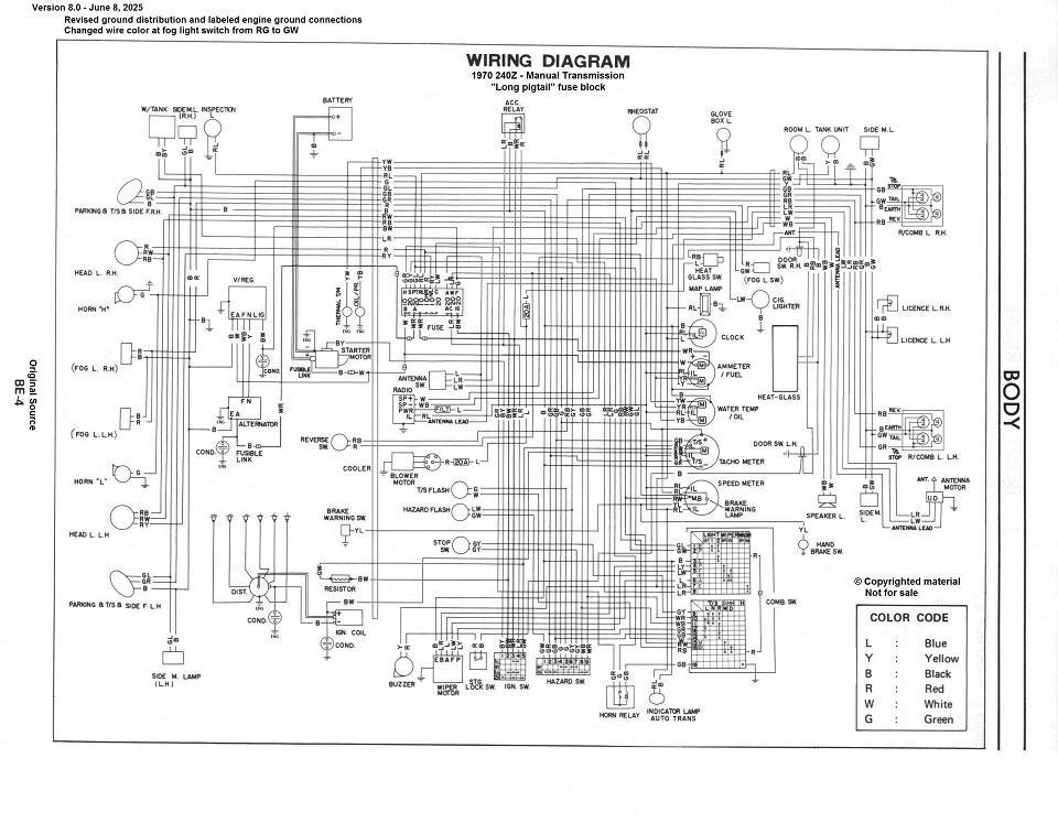
I messed around a bunch with the early car wiring diagram. The results are here and the current version (v8.0 at the time of this writing) of my wiring diagram can be found on page seven: https://www.classiczcars.com/forums/topic/69026-1970-wiring-diagram/ I do not know, however, if your 1/71 car is the same as the 7/70 I was using as my guide. Probably very similar, but not necessarily identical. That, and it sounds like your car has been customized some, so it will clearly differ there as well. Looking over my wiring diagram, the only pair I found for R/L and B is for the auto transmission indicator lamp. I'm thinking that the wires in your red circle are for the defroster? Is it a L and R/B? I can't see any stripes on the red, but it may be on the back side. Take a look through the diagrams and maybe you can find some help in there?
-
Can you clarify a little bit about the order of events? You drive the car and the brakes are soft. You get home and bleed the brakes and immediately after bleeding they feel good solid firm. You go to bed and get up the next morning, and the brakes are spongy again after sitting static overnight. Is that the correct order of events?
-
I believe this is the case. Which would make the thread in question a 1/2-14 BPT. The thread differences between the 1/2-14 NPT and BPT are relatively subtle.... NPT uses 60 degree threads, while BPT uses 55 degree "Whitworth" style threads. So while the pitch is the same, there are some minor differences in the shape of the peaks and valleys. That said, if you run an NPT fitting in there nice and tight with some thread sealant, it'll probably seal up just fine. Not the "correct" solution, but happens a lot.
-
Hmmm... Maybe the Z is just a transportation method?

-
It is typical for the actual diameter measurement of external threads to be a small amount below their designated size. In other words, it would be expected that an M3.5 screw to be slightly smaller than 3.5mm in diameter.
-
Well my assumption was that the comment I responded to was meant for you. I was happy that you were up and moving about! Hope to see you again sometime, and in the meantime, share away!!!
-
Yeah, I think the PCV system is much misunderstood. I guess it's one of those seemingly simple things that "just is" and many people don't really know that it's more sophisticated than it seems at simple quick glance. But I have to agree.... I don't see the need to have 1000 different PCV valves. It's like oil filters... Couldn't engine designers spend a little more effort on reusing sizes and shapes that already existed??
-
I would expect that pretty much all V-block engines run ports on both valve covers. One to PCV vacuum and the other to atmospheric at the air cleaner. Flow through from one valve cover, down into the block, and out the other valve cover. And I don't know about all modern inline engines, but I can tell you from hands on experience that early 2000's Civics and late 2000s Hyundais have a system that is conceptually identical to the Z. Vent on the valve cover and PCV connected to a port on the block. Even though those examples aren't really new, I would consider them to be "modern". Ish.
-
What he said!!
-
Well my thoughts are that unfortunately you do not really have a perfect solution for your example. If there is no balance tube on the triples, then there's no "symmetric" location to put a PCV valve. As you suggest, without an evenly balanced place to put a PCV, one pair of cylinders will suffer if you were to just stuff it into one of the intakes. I would, at least, as Duffy suggested, run a catch can on that port on the side of the block. At least that way, you would have two holes a-huffin and a-puffin as the pistons went up and down instead of just one (on the valve cover).
-
As Zed Head suggested, blocking off the vent hole in the side of the block will eliminate the entire "positive" part of PCV. The whole concept behind the system is that you positively have crankcase ventilation under all running conditions. Using two ports combined with the PCV valve, you get flow through ventilation at all times, under all running conditions. By just using the single port on the valve cover, you lose the benefits of positivity venting your crankcase and you will not have any flow through venting.
-
Seconded. That groove is an attempted insurance policy in the event of a gasket failure and coolant leak. It's supposed to route leaking coolant out the side and onto the ground instead of routing it inside the block where it would mix with the oil.
-
Hahaha!!! Well, I couldn't keep a straight face!!
-
Here's a couple pics of stuff I have here. Idle screw not touching the linkage: This carb closes down pretty far, but I've seen them close down even further. So I took a look at the linkage over by the stop screw, and it looks like on this carb, the tang on the linkage may be contacting the carb body a little bit even when the idle stop screw is backed out beyond contact. Take a look at yours and see if maybe you've got something like that going on with yours. Might just have to bend the tank down a tiny bit to provide a little more clearance?


-
Well I have no idea if the M66 is the correct needle for your application, but I did a few minutes of web searching and came up with a couple hits: https://ratsun.net/topic/57757-needle-modification-for-l20b-sus/ http://www.team.net/html/datsun-roadsters/2000-07/msg00225.html https://ratsun.net/topic/52225-hitachi-side-draft-su-needles/ There was some mention that the M66 run rich at idle, but then go lean at higher throttle positions. So yours sound like they are following that pattern... At least the idle part.
-
OK, so 0.090 nozzles. Do you know what needles are in there (and what needles are supposed to be in there)? And even if they are appropriate needles and nozzles, it could still be a problem there. They might have worn from rubbing due to incorrect alignment. Or corrosion over the years eating away at the brass. Those kinds of issues would be most pronounced at idle since the gaps are (supposed to be) so small.
-
Kinda sorta, but in theory, only on transition. Running steady state, the oil viscosity should not have any effect at all. The impact of the oil would be most pronounced on increased throttle position, like when you punch it.