


Captain Obvious
Free Member
-
Joined
-
Last visited
Everything posted by Captain Obvious
-
 @Patcon, Didn't you tap a hole in a master cyl for some reason? Don't remember if it was brakes or clutch, but I do remember you doing something like that.
 -
In all seriousness, I would assume it's an air vent to let the ozone out?
-
Home Before Dark!!
-
Well one difference between adding a resistor to the temp sensor circuit and messing with the AFM is you can only make it richer with the resistor, not leaner. By messing with the AFM, you can (in theory) do either. So out of curiosity, Is there a problem here you're trying to fix? Or is this an academic discussion only? And... Where did you read that?
-
I've wondered the same thing, but I don't have a spare tach here for analysis. If someone wants to send me a later design tach for investigation, I'd be happy to put it on the operating table.
-
@HusseinHolland, Yeah your car left the factory without air. Your HVAC system is all manual. All cables, no vacuum,
-
I wasn't there when they designed it, but my theory (based on my own experience*) is they found that the thermostat housing was completely dead-ended in 75 when they switched from carbs to the FI. You see... The carbs had water that ran through the intake manifolds and other locations depending on the year, but in 75 that all disappeared. In 75 if it weren't for that "bypass" the thermostat housing did not see any flow until the thermostat opened, other than the little hole in the thermostat. I'm thinking the hole in the themostat wasn't enough flow and they noticed that the engine temp got hotter than desired before the thermostat opened (because it was sitting in a stagnant pool of cold water). Then in 76 they piped it through the heating plate under the AAR. I'm thinking 75 was the only year they needed to put in a bypass simply for the sake of a bypass, * I'll go into it if anyone is curious, but not really necessary for this discussion.
-
Me too!! Hopefully we'll be able to get the band back together soon!!
-
LOL!! Looks like me!!!
-
Well you could always just cut (break) the plastic cover off the switch. At some point in the evolution they decided that cover wasn't necessary anyway. And if you're still skittish about it, you could just wrap a couple rounds of tape around the whole switch body to recover it after you've reattached the wire?
-
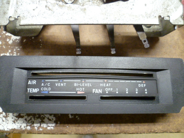
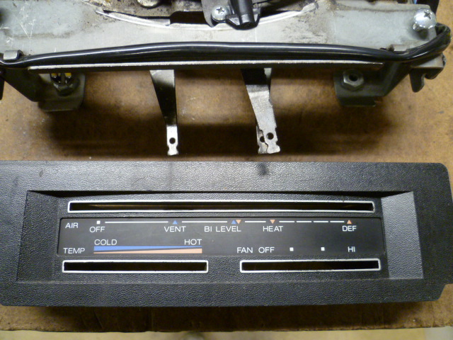
Hard to tell from that pic... Start simple. Take a pic of your HVAC controls. Does it have a setting for A/C or not? Here's a pic of a non-AC control head: And here's an example what it looks like if you have factory air:
-
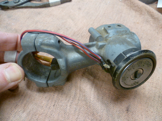
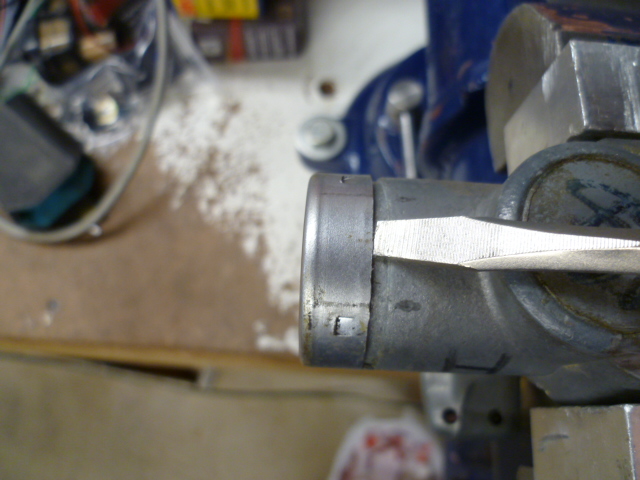
The later versions of that "key in the ignition" switch that I've messed with don't have that plastic shroud over the connections. Not sure if they changed the design over the years, or if the ones I've messed with had the cover removed by a PO at some point. In any event, these pics should help. Start with this: Remove this. Should pull off by hand: Then remove this. Should come off with some light taps: Where to go after that should be obvious:

-
Yeah, it sounds like you hit the limit of your press capacity. That's exactly how it feels when you hit the pressure limit. Why don't you give SteveJ's 20T a try? Always fun to have someone watch over your shoulder you as you sweat nervously while you have something under 19.5T of pressure.
-
I suspect the U-joint spider is heat treated and would be difficult to drill and tap. Depends on how hard they made it. I know the tips where the bearings contact have to be quite hard. The body doesn't need to be that hard. but unless they selectively hardened the tips (inductive heating), the whole body would be hard. I'd hit it with a file first to see how hard it is. If the file just skates, it's a tough job to drill and tap that.
-
I'm guessing that @Patcon uses the same "show me all of the new activity in the past 24 hours" feed that I do. And since they all occurred in the past 24 hours, all of them show up. Between the two recent topics, I get six of them. I thought you were having internet troubles and were getting duplicate posts. I certainly didn't think you did that on purpose. Before people replied to some of them and split them up, I got just about a whole screen of it! "Fairlady Z's topic in USA Eastern pic in USA Western y Z's topic in Canada d a topic in Canada a topic in USA Eastern in Maryland Z Club's Discussions"
-
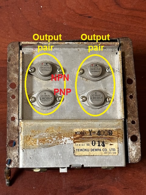
Well without spending real time on it, that's about all I have from a distance. Have you found a shop willing to take on the work? In my experience with such devices, the amount of time/expense required to diagnose and fix something like that is very rarely worth the dollars. In this instance, it's a piece of history that is irreplaceable which makes the value indeterminate. And one of the problems is certainly going to be obsolete and unavailable parts. I already looked around on the interwebs for the output transistors (the four big ones bolted to the aluminum plate) and they are (not surprisingly) unavailable. PNP germanium in a TO-3 case. Riiiiiight. Haha! Send me a PM if you're still looking for a shop and want to chat. I could use some vapor blasting. Or some $$. Or a some of both.
-
Can you snap a couple pics of what you have. Should be pretty easy to tell if it's factory or aftermarket.
-
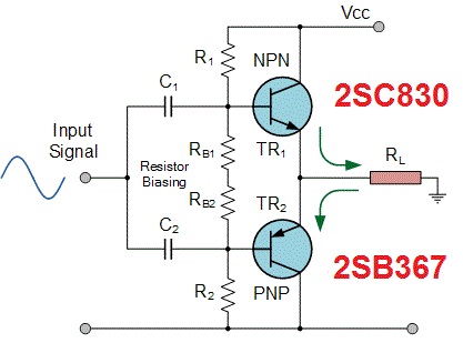
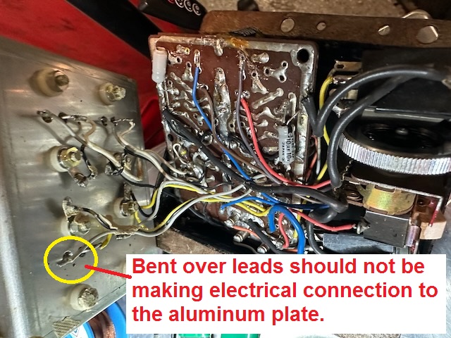
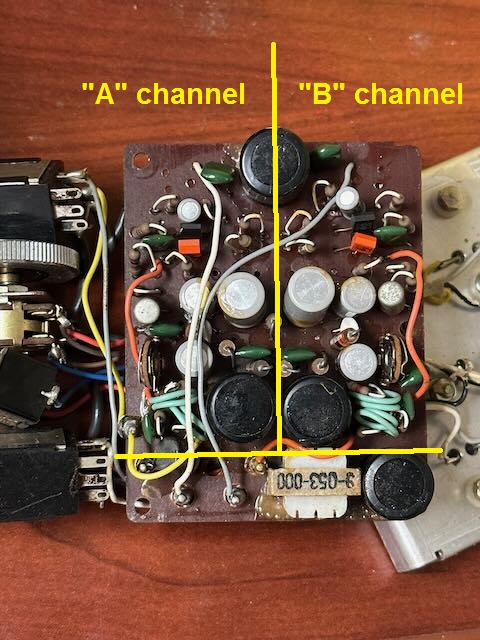
A little more info to help out... You shouldn't have to spend a lot of time figuring out how the four big output transistors are connected. I can tell you that they are "push-pull" amplifiers consisting of a pair of NPN and PNP transistor pairs. In other words, each channel has a pair of complementary transistors, one NPN and one PNP. Like this: With credit to the source - https://www.electronics-tutorials.ws/amplifier/amp_6.html. Schematically, they are connected basically like this. Note that the surrounding components like the resistors and caps are most likely a little different, but the basic scheme looks like this: One other thing to note is that the four big output transistors should be electrically isolated from the aluminum plate to which they are mounted. They are bolted to the aluminum plate as a heat sink, but the connections should be mechanical only, not electrical. With that in mind, things like bent over leads making contact to the plate would certainly prevent the unit from working, and could cause permanent damage. Can't tell from the photos if there is actually contact, but if there is, there should not be. For example:
-
That board is mostly symmetric about the middle. Undoubtedly the two independent channels. It'll save you quite a bit of time with the reverse engineering because you only have to do half. This is what I mean: I would guess that the few components at the bottom of the pic that are not symmetric (the coil and the big cap) are most likely input power filtering, and the big cap at the top is most likely a power supply filter as well. The big ring of solder trace around the board perimeter is ground and the big strip running down the middle is most likely the high side of the supply.
-
Yeah, I'm not yet convinced some light on the test light is a problem. As for what you're hunting..... Blown speakers? First question would be "What's your typical listening volume?"
-
Well it was a couple years ago when I was messing with those bushings, but I don't remember it being that hard of a fight for me. Are you maxxing out your 12T press? You can usually tell by feel of the jack handle when you hit the bypass limit. Are you hitting the limit? And that press you pictured is what I have. An old HF "A-Frame" 20T. I don't think they offer it anymore. Last I looked, they still offer an "H-Frame" in 20T and an "A-frame" in 6T, but for some reason it seems they dropped the 20T "A-Frame" a number of years ago. Probably unsafe or something.
-
I'm thinking seeing a light up on the test light might not be a problem. Kinda depends on how the amplifier is designed and where you have the test light connected. And a test light is different than using a digital meter... The test light doesn't care about DC or AC. All it cares about is average power. So the test light might light up some even if you read zero on your meter on the DC scale. So how did you have the test light connected? One side clipped to body ground and the other side probing the speaker wires? And if yes, did you probe both speaker wires? What happened?
-
Couple things... First, it's not DC, so if you're using a meter set on DC, you won't see anything. Then next, if it's music, it's a whole bunch of frequencies all mixed together up to about 20KHz. So even if you have a meter set on AC, it might not recognize frequencies that high. And finally, the voltage peaks will be proportional to how loud the music would be. So trying to make some sort of "portable scale" to measure things... If you've got a 20W system turned all the way up, it would/could/should? light a 20W bulb to a reasonable brightness. But if you've got the volume turned down to a reasonable listening level, the brightness will be way lower. Not sure I'm doing a good job of explaining this... Does any of that make sense?
-
Unless you are planning to go with poly, then burning them out won't do you any good. You'll still have to get the outer shell out before you press the new bushings in. You could burn the rubber out and then use a hacksaw to cut through the outer shell to relieve the retaining force. You don't have to cut 100% of the way through... It'll start to cave in before you get all the way through. Even with a couple thousandths remaining and it will be a lot easier to press out. I did mine (whole without burning) on a hydraulic press, and like most operations on a press, it all comes down to having properly sized drifts and anvils. A square (normal) force applied in the correct location with the proper sized backup anvil should do it. How many tons is your press? I've got a 20T and had no problems.
-
Couple ways... First (as foosman mentioned) as fuel is removed from the tank, the volume of that fuel must be replaced. Another way is if you park the car with a hot tank of fuel, that fuel will contract as it cools and could cause a vacuum. In any event, the solution to this is NOT the flow guide valve, but is in fact the gas cap. There is a one way check valve built into the gas cap that will allow air to pass through the cap into the tank to alleviate tank vacuum. The direction of air through the flow guide valve is uni-directional. They are check valves. No guarantees if they still seal after all this time and gunk, but they are supposed to be check valves.


