


Captain Obvious
Free Member
-
Joined
-
Last visited
Everything posted by Captain Obvious
-
 Did this a couple years ago on my daily:
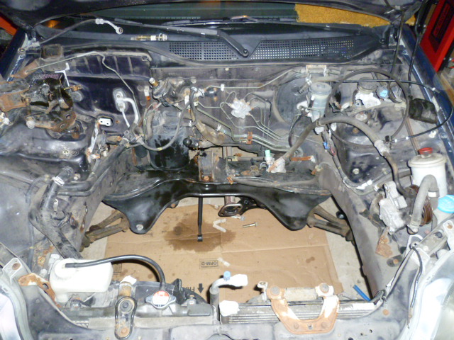
-
Thanks for the offer bud! Appreciate it!
-
Thanks Bud! Yeah, I'm OK, but honestly have been better. I got covid at Thanksgiving and am still working out a couple kinks. Still. Hoping 2023 is better than the end of 2022.
-
I don't even know what to say. This should be ripe with all sorts of great comments, but I'm in analysis/paralysis.
-
For some additional input about air dams... @Av8ferg
-
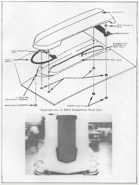
Yeah, if I took my car into the dealer for a problem and it came back to me with that huge thing on the hood "to fix it", I would not be very happy about it! "Massive"... In your part of the world, that reminds me of other things like "snarlin", "bone dry", "hobblin" and the Good Ship Grease.
-
Couple comments... First, the Obvious one. That's a master cylinder, not a slave. Second... Be real careful about burrs kicked up into the cylinder bore as a result of the tapping operation. If there's a burr in the area swept by the cup seal, it'll chew it up right quick!
-
I'm pretty sure the brakes are supposed to rub when you hit the brakes.
It's part of a line from an old Beatle's song. "No thank you please, it only makes me sneeze. Then it makes it hard to find the door." But they mispronounce the word "the" a little bit, and it sounds more like "dee", At least to me... After sniffing the houseplants. https://youtu.be/Ag6wyMNLv_A?t=34
And then it makes it hard to find dee door.
It's been pretty cold here too. It went below zero last night, and hit about 20 today in the sun. Tomorrow I think is supposed to be slightly warmer... Like 26 maybe? In any event, mighty cold. But still way warmer than the north central US and central Canada, so I'm not complaining. That's brutal.
Haha! Try to stay warm, my friend!!
I think "tumbler" and "wafer" are pretty much synonymous when referring to this kind of lock. Yes, the "Right" or "Left" style of lock comes down to the cylinder casting, meaning that the key blank will only fit into the correct style cylinder. But they all share the same tumblers. As for the wear grooves in the outer shell, I don't have any good suggestions about how make those better. The lock cylinder and other body parts are (I think) cast zinc. Cheap, easy to work with, easy to get fine detail and accuracy. All of that makes it a popular choice for locks. Note that "durability" is not in that list of properties. And I don't think epoxy will last long. It's softer than the zinc. Ideas? Find a NOS replacement. Pay someone to make a whole new one. Live with it.
I suspect our resident librarian is too cold... Huddled up in a chair in front of the space heater with a warm fireball? Let me cover for him on this one: https://www.classiczcars.com/forums/topic/35919-new-challenge-anyone-had-warped-tail-light-flanges-before/#comment-644526
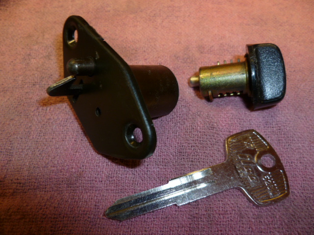
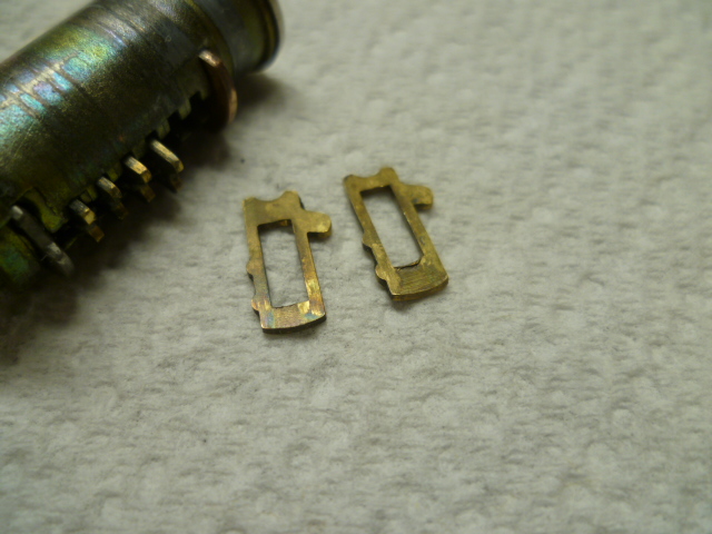
I re-keyed my glove box along with the rest of the locks on the car. However, my 77 uses the newer (74 on) style lock. I haven't messed with an older style glove box lock. Mine looks like this: While the older style looks like this. I've not messed with one of these, but I expect it to be conceptually similar to the rest of the locks: So about the tumblers for the ignition locks... I believe the only difference between the tumblers for the ignition and the rest of the car is a slight change in profile at the top of the tumblers. Here's a pic of a couple ignition tumblers. Note the concave shape to the top of the outline. The doors, etc do not have that concave feature: Everywhere else on the car, the tumblers are domed (convex) on both top and bottom. With that in mind, ignition tumblers are able to be used in other locks, but I don't remember what that concave feature is for, so I can't offhand tell you if door tumblers would work properly in an ignition application. I'll have to dig my (three) lock box off the shelf and re-familiarize myself with that detail.
 Uh-oh.
That's what I did. I had enough tumblers that I re-populated my locks the way I wanted them and then cut my own key to work with them. Turned out great. I'm gentle with the door locks now. I try to apply juuuuuuussst enough pressure to unlock. Trying not to smear the soft metal so I don't have to ever mess with them again.
Yeah, I was sure the math you cited was sound, just misapplied. We're good now. And, the duplicate thing exists, but unless you go trying your key in other people's cars, then how would you know? Just like you and your buddy with the pranking. Haha!
And if there was a left and a right option for key blank, then the numbers double. So 1024 for each blank resulting in 2048 possibilities total. But no... I really don't think there were any "locksmith adjusted" tumbler modifications in the field to get more than that.
Respectively submitted... I don't think you are reading everything correctly. As an example, I know that if you have ten different choices and two different spots to put them, you have 100 different combinations (00 to 99). Ten to the exponent of two. Four different choices and five different spots to put them results in 1024 combinations. Four to the exponent of five.
I was wondering if you were talking about the lock code. There is likely no correlation between "lock code" and wafer numbers or positions. In fact, if there were, it would be unreasonably easy to figure out which wafers were used in which lock. In other words.... If "lock code 1234" corresponded to wafers numbered 1-2-3-4 in that order, then that would be all you would need to make a key for that lock. Not much security there. I think the "lock code" is just that... A code. Recorded and stamped into the body when the lock was populated with random wafer numbers in random positions. Just because the lock code can seemingly go from 0000 to 9999, I don't think there is anything to be gleaned from that number as far as the wafers are concerned. And yes, there could be duplicates. But without the code book, that's fine. How would you know? If you have four wafers in your early hatch lock and there are four different wafers, then you have 256 different possibilities. I think I have five wafers in my later hatch lock which provides 1024 possibilities. Seems like they added an additional tumbler to the hatch just like they did with the ignition lock.
No, the rectangular slot does not vary in height. It varies in position. The position of the slot will be closer to the top of the tumbler for each tumbler. If you look closely at the pic you posted of from the ASP catalog, you can see they tried to draw them that way. It's a subtle difference, but enough to make the lock work. Goes like this: And about the number of tumblers... I'm no locksmith, but I've only ever seen four different tumblers for these locks. Where are you getting numbers between 0 and 9? I don't know if they changed the number of tumblers in the hatch over the years (like they did with the ignition lock), but my 77 has five tumblers in it. With four choices of tumbler for each position, that works out to different 1024 possibilities.
Uh-oh.
That's what I did. I had enough tumblers that I re-populated my locks the way I wanted them and then cut my own key to work with them. Turned out great. I'm gentle with the door locks now. I try to apply juuuuuuussst enough pressure to unlock. Trying not to smear the soft metal so I don't have to ever mess with them again.
Yeah, I was sure the math you cited was sound, just misapplied. We're good now. And, the duplicate thing exists, but unless you go trying your key in other people's cars, then how would you know? Just like you and your buddy with the pranking. Haha!
And if there was a left and a right option for key blank, then the numbers double. So 1024 for each blank resulting in 2048 possibilities total. But no... I really don't think there were any "locksmith adjusted" tumbler modifications in the field to get more than that.
Respectively submitted... I don't think you are reading everything correctly. As an example, I know that if you have ten different choices and two different spots to put them, you have 100 different combinations (00 to 99). Ten to the exponent of two. Four different choices and five different spots to put them results in 1024 combinations. Four to the exponent of five.
I was wondering if you were talking about the lock code. There is likely no correlation between "lock code" and wafer numbers or positions. In fact, if there were, it would be unreasonably easy to figure out which wafers were used in which lock. In other words.... If "lock code 1234" corresponded to wafers numbered 1-2-3-4 in that order, then that would be all you would need to make a key for that lock. Not much security there. I think the "lock code" is just that... A code. Recorded and stamped into the body when the lock was populated with random wafer numbers in random positions. Just because the lock code can seemingly go from 0000 to 9999, I don't think there is anything to be gleaned from that number as far as the wafers are concerned. And yes, there could be duplicates. But without the code book, that's fine. How would you know? If you have four wafers in your early hatch lock and there are four different wafers, then you have 256 different possibilities. I think I have five wafers in my later hatch lock which provides 1024 possibilities. Seems like they added an additional tumbler to the hatch just like they did with the ignition lock.
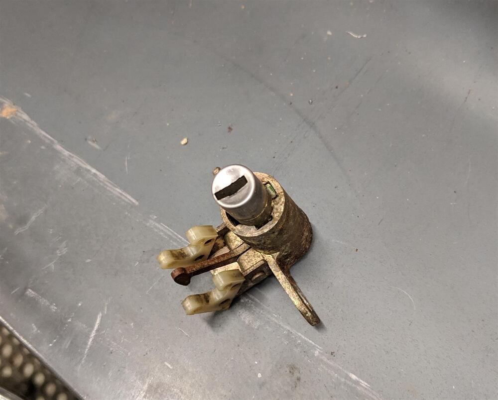
No, the rectangular slot does not vary in height. It varies in position. The position of the slot will be closer to the top of the tumbler for each tumbler. If you look closely at the pic you posted of from the ASP catalog, you can see they tried to draw them that way. It's a subtle difference, but enough to make the lock work. Goes like this: And about the number of tumblers... I'm no locksmith, but I've only ever seen four different tumblers for these locks. Where are you getting numbers between 0 and 9? I don't know if they changed the number of tumblers in the hatch over the years (like they did with the ignition lock), but my 77 has five tumblers in it. With four choices of tumbler for each position, that works out to different 1024 possibilities.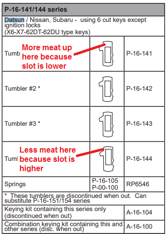 They differ by changing the where the location of the rectangular hole is with respect to the top and bottom edges. When you get the right wafers in the right spots and insert the right key, it should look like this pic. Note that the wafer farthest from the key is used simply as a retaining device for the cylinder to be held into the lock body. In other words... It should always be proud, even with a key inserted. Looks like this:
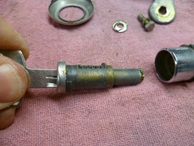


Important Information
By using this site, you agree to our Privacy Policy and Guidelines. We have placed cookies on your device to help make this website better. You can adjust your cookie settings, otherwise we'll assume you're okay to continue.